- Joined
- Nov 4, 2020
- Messages
- 80
- Points
- 103

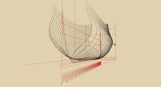
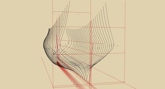
Let us not delve into the performance comparison of specially designed ships with high deadrise (or we will end up discussing Symonds and Forfait, which is totally out of scope here).As for deadrise, indeed, it is directly related to stability. The best known examples of large ships with extreme deadrise are probably the Symond's designs. Excellent sailing ships, but hopeless gun platforms.
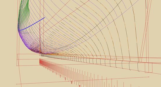
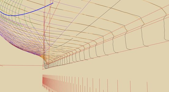
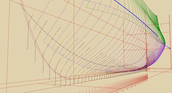
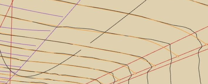
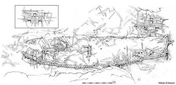
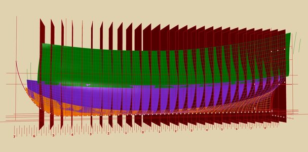
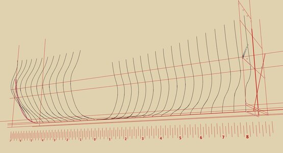
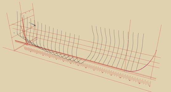
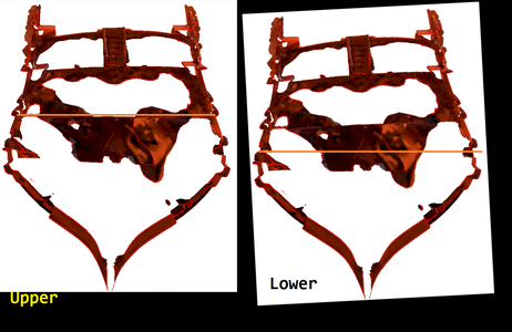
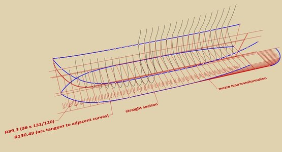
What I meant to say is that there was (I am not sure how common, but it certainly existed) a method of adding deadrise to, let's say, otherwise traditional designs specifically to increase performance, which may have been proposed by Sheldon as one of the modifications to the design he brought from England during the design phase of the Riskäpplet, and so it is possible the deadrise we see on the model is intended to be there. This may, by the way, account for discrepancies in depth-in-hold measurements in some way.
Last edited:


