Naseby 1655 - reverse engineering the ship model

.​

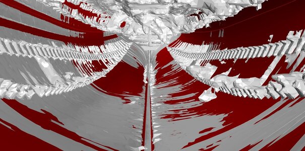
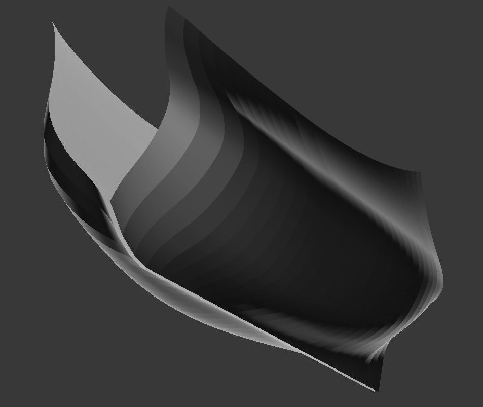
Just to show something in the meantime. Apart from the expected inaccuracies of the workmanship and a variety of subsequent, various and heavy natural distortions, the most acute at this stage of the reconstruction are the apparently splayed sides, which must have come off from the deck beams somewhat. Randomly.


ViewCapture20230522_100126.jpg

.​
 
Last edited:
.​

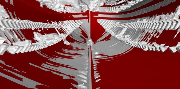
Close, very close. Even the partially corrected digital model still has the shape of a zigzagging snake, in different ways at different levels. Therefore, for visual shape verification, it has to be moved laterally by 1, 2 or sometimes 3 inches. The more mottled, the better.


ViewCapture20230522_202202.jpg

.​
 
Last edited:
.

But even before that, a correction stage, because Martes has not the slightest intention of allowing the production of a rot:


„As a quick review of the obj ->

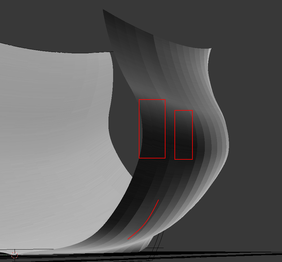
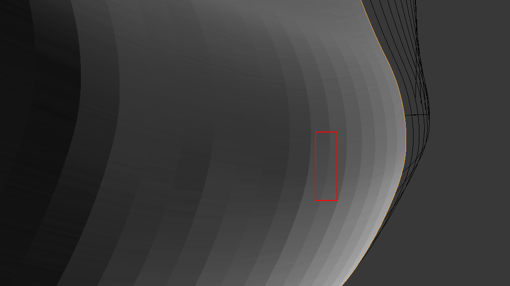
The midship inrregularity is still present, but much less acute:


image.png.03af316718ce40b4f05e6ec0eec4d0c7.png
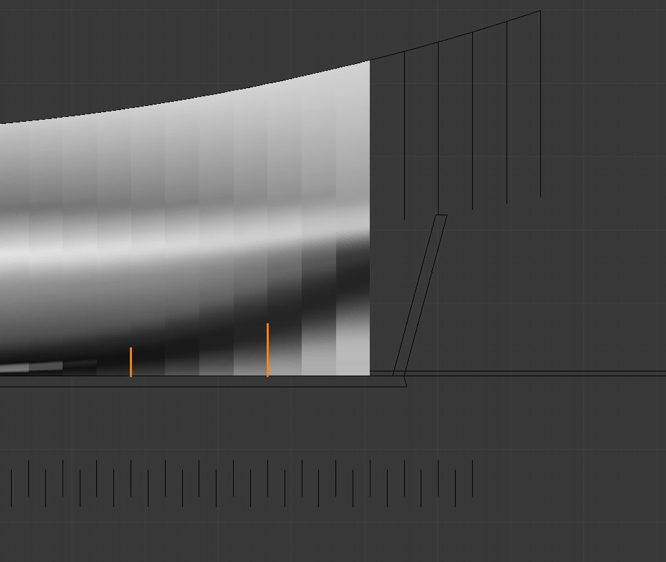
Although I am not sure if something isn't wrong with the midship floor sweep accidentally,

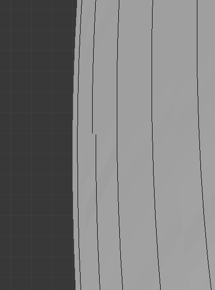
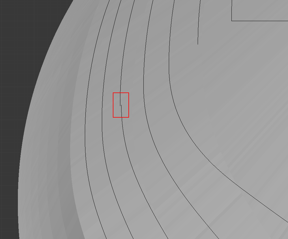
and there is a disconnected line on the 18th station if counting from the bow:


image.png.b61c108be883b438d35bdd1b339ea5cf.png

where I assume the lower breadth sweep has gone wrong. I connected the lower control point to the upper to create the surface, and it looks more or less all right, but I suspect the lower breadth sweep radius is still wrong there:

image.png.3a9b044499a0e28c2e0355e02416a840.png

And the same disconnect is observed on the 3rd frame from the aft:

image.png.e129b68eb7154a1460648422112c4160.png

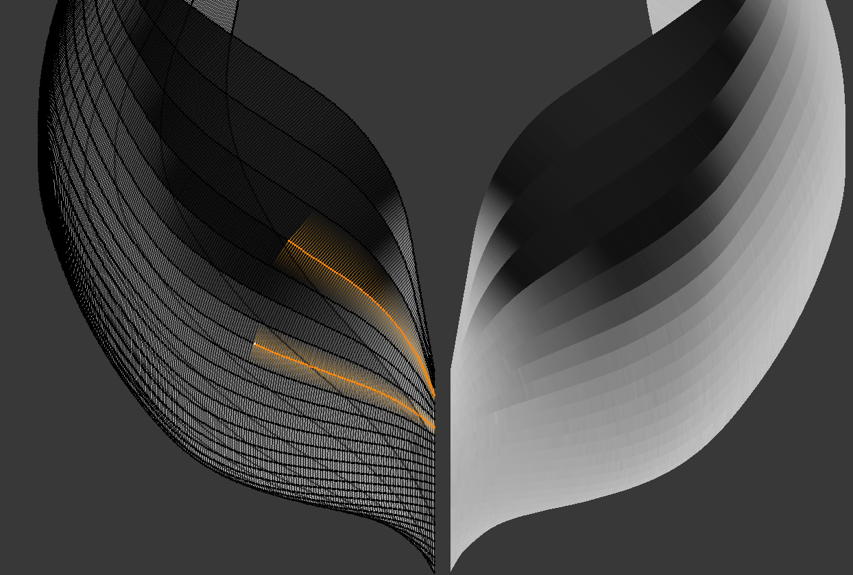
Additionally there are two hollowing curves aft I would put a question mark on as they are pronounced too strongly in comparison with their neighbours, but they were present before, I just noted only one of them in my previous review:

image.png.4749f6ab14235fe92ad0b97d2b43b473.png
On the 4th and 8th stations if counting from the last full station aft.

image.png.37ca46b92a93e164dcee214c91a70ea5.png

I must add the fore half is perfect in this regard:”

image.png.f8bb69624560570f15846b043d1aa28c.png

.​
 
.​

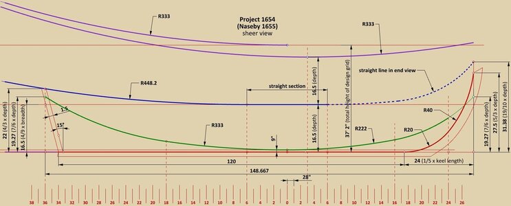
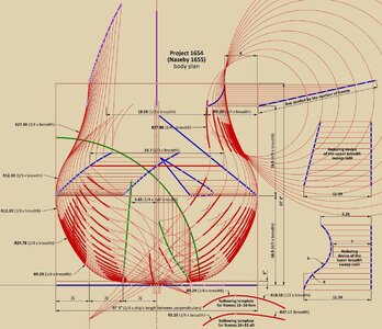
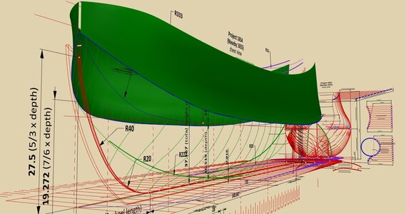
This is the last iteration of the reconstruction and the following can be considered the final conclusions of the mostly graphic analysis of the digital Ö 3 model.

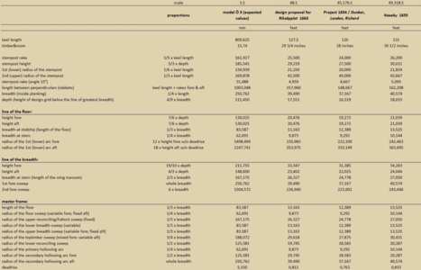
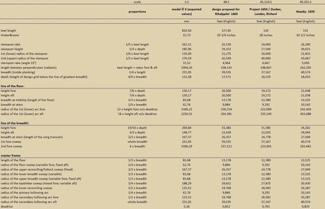
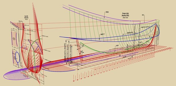
The diagrams below show the design structure of the model as I have read and interpreted it. Although the dimensions are given for a 120-foot keel length ship, the accompanying table also includes other values as well, calculated proportionally for a 131-foot keel length ship (Naseby 1655), for a 1:48 scale ship (the alleged Riksäpplet 1663 design) and in millimetres for the model itself.

The largest number of round values occurs for Naseby 1655 (or Project 1654, depending on what is considered more important), but in practice this could not necessarily matter much, since, as can be seen in the table, practically all dimensions were calculated in a proportional manner and not always rounded in actual building. It should be noted, however, that the proportions of the model are perfectly in line with the known dimensions of both the original project 1654 (i.e. for Richard, London and Dunbar) and Naseby 1655. The difference in breadth is naturally the doubled thickness of the hull planking at the level of the greatest breadth.

Actually, proper "classical" plans still need to be made, but this is very time-consuming, so it is better to wait a little longer for any possible comments from readers that may still contribute some concrete and useful information.

Again, I would like to thank Martes for his various conscious and unconscious help with this project :).

Waldemar Gurgul


Tabela.png


ViewCapture20230525_135038.jpg


ViewCapture20230525_133950.jpg


ViewCapture20230525_132537.jpg

.​
 
Last edited:
.​

Yet another, quite important comment.

The size ratio of the Naseby 1655 to the Ö 3 model in 1:48 scale is exactly the ratio of English foot length (304.8 mm) to Swedish foot length (297 mm), which can hardly be considered a coincidence. In other words, the Ö 3 model can be considered as a model of Naseby 1655 in normal 1:48 scale, only further reduced in the ratio 297:304.8.

Thus, if the size and proportion criteria are deemed decisive, the Ö 3 model must be recognised as a design proposal specifically dedicated to the Swedish customer, but representing in fact a ship perfectly matching the proportions of the known dimensions of Naseby 1655, and also her nominal size in feet, only reduced from the length of the English foot to the length of the Swedish foot.

To put it yet another way, Francis Sheldon's proposal is in fact Naseby 1655 at the scale of 297:304.8. It's a 131ft keel length ship design, just like Naseby 1655, only Swedish feet, not English.


Edit:
The same conclusions, more or less, had already been made by the Swedish historian Jan Glete.


.​
 
Last edited:
>The size ratio of the Naseby 1655 to the Ö 3 model in 1:48 scale is exactly the ratio of English foot length (304.8 mm) to Swedish foot length (297 mm)

If this was conscious decision, it is, again, an extremely elegant solution to - possible - Swedish request to slightly reduce the size of the ship. Sheldon ought to have had a whole heap of detailed tables with sizes of scantlings and everything, and would have been surely tempted not to recalculate them to new scale (or, if one thinks of it, convert the original to Swedish dimensions, so he might have as well pushed for size reduction himself), but leave the numbers as is.
 
.​

I rather dare not decide whose initiative this was. We are simply seeing the effects of it. But the difference in the absolute size of the ships was quite negligible, so if I had to, I would rather point to Sheldon. For the very reasons you mentioned above.

.​
 
.​

If this was conscious decision, it is, again, an extremely elegant solution to - possible - Swedish request to slightly reduce the size of the ship.

I think I'm starting to guess what happened, but I'll stipulate that this is just speculation:

Sheldon must have lied about this being a new, original project that he had worked very hard on (with possibly all the accompanying tables of scantlings, masting, rigging, etc.), and for which he got 100 ducats, while in reality it was ready-made Naseby 1655 design. He merely reduced the size of the wooden model according to the ratio of English to Swedish feet, so as not to recalculate anything else. Later, when the scrupulous Swedish authorities somehow found out about this deception, they simply reduced Sheldon's salary accordingly. The latter did not even try to protest, but simply asked for the return of the incarnation of his 'new' project, i.e. the wooden model. Of course, neither side cared to publicise this embarrassing affair. As a classic said: tempora mutantur, sed homines idem manent...

However, from today's point of view, it is even a quite fortunate coincidence. Three birds with one stone :)...

.​
 
Last edited:
.​

Below is a dimensions table, updated to the more consistently applied calculation formulas, although the differences in the values given are actually negligible compared to the first version, shown in post #105. Just for the sake of precision, should anyone need it.


View attachment 377039

.​
Wonderfull work Waldemar, love it.
So with the data above you can reshape the lines of the 1654 London, the famous ship that was blown up in 1665 by mistake.
The ship was drawn from front and stern by Van de Velde which would make it a possible candidate for a reconstruction.
Were these ship build according the same lines?
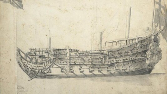
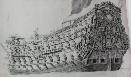
_103433758_portraitofthe'london'bywillemvandevelde-cnationalmaritimemuseumlondon.jpg_90830628_thelondon1.jpg
 
.​

Thank you very much, Maarten. The case of London 1656 is particularly interesting, because even the 'plans' of this ship have been preserved. The trouble is that these 'plans' are decorative in nature and are, in a very expert way anyway, simplified. As a result, difficult decisions will have to be made as to which elements of the London 1656 'plan' should be taken literally and which should be interpreted, and how. For this possible interpretation, the design methods that have just been read and shown here, i.e. of Project 1654/Naseby 1655/Riksäpplet 1663, will be particularly useful indeed.

We're going to do it with Martes, and show it in a new thread, but of course the current project needs to be finalized first by drawing the ship's lines in today's normal convention.

.​
 
Last edited:
.​

Thank you very much, Maarten. The case of London 1656 is particularly interesting, because even the 'plans' of this ship have been preserved. The trouble is that these 'plans' are decorative in nature and are, in a very expert way anyway, simplified. As a result, difficult decisions will have to be made as to which elements of the London 1656 'plan' should be taken literally and which should be interpreted, and how. For this possible interpretation, the design methods that have just been read and shown here, i.e. of Project 1654/Naseby 1655/Riksäpplet 1663, will be particularly useful indeed.

We're going to do it with Martes, and show it in a new thread, but of course the current project needs to be finalized first by drawing the ship's lines in today's normal convention.

.​
That would be great, especially as there is a well preserved wreck of the London and maybe even a part of the actual construction details could be retrieved from archeological data.
This would be a great journey.

Is there a link to the plans of London? Are these part of the nmmg archieves.
 
.​

Such aspects as searching for (and finding) interesting things are normally more Martes' domain and speciality, but I will replace him in this case exceptionally :). And now rather unlikely to get any concrete data from the archaeological site. They must have top secret status until eventual, 'official' publication, whatever that means.

Voilà:


.​
 
Last edited:
And now rather unlikely to get any concrete data from the archaeological site.

Add to that the awful state of the wreck and its continuous deterioration. We'll be lucky if anybody gets at least some floor timbers out, if ever.

@- Waldemar - (and me) would have quite a lot to say about those plans and the London herself, but that's for somewhat later, because the model provides the base project we were badly missing when we first encountered the plans.
 
Last edited:
.​

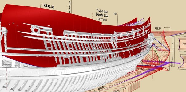
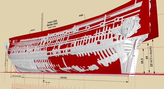
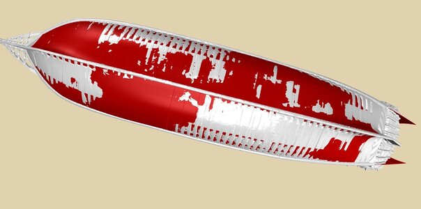
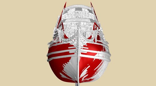
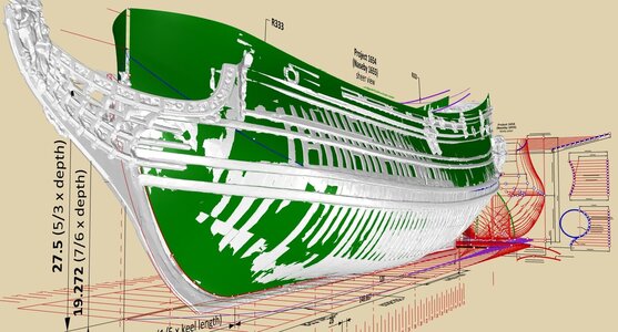
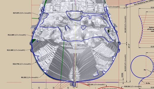
For the final reconstruction, I decided on a more ambitious variant with a tapered keel. According to the model it is about 5/6 at the bow and 2/3 at the stern of its whole width. This change of approach, although seemingly minor, provoked another series of time-consuming adjustments, yet, at the same time, allowed to see the places that can be further refined. As a result, a certain number of modifications are still to be expected. However, most things, especially the main dimensions, will remain the same.

For now I can only show the work-in-progress graphics.

In the last diagram, another method of verifying shapes, by sectioning together by one plane the original model and the surfaces reconstructed by ancient methods. Visually it is more impressive as animated, with dynamically changing shapes. As can be seen, there is a very good coverage of shapes in the underwater part of the hull (the blue cross-sectional lines overlap), while the upper parts of the model are clearly dislocated, both sides in one direction.


ViewCapture20230602_122145.jpg


ViewCapture20230602_122444.jpg


ViewCapture20230602_122831.jpg


ViewCapture20230602_164528.jpg

.​
 
Back
Top