Naseby 1655 - reverse engineering the ship model

.​

Thank you Allegheny. I can really see the end of this project now, as I have just finished the analysis and interpretation stage. Now all that remains is the presentation etc.

* * *​

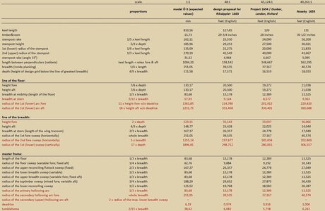
The keel in the reconstruction 3D model is already tapered and the resulting shapes are more than satisfactory, especially given the extreme distortions of the original model. The initial intention was at least to get information about the design structure only, but in the end it was also possible to find out the exact dimensions and proportions used by its 17th-century creator. This simply could not be done any better.

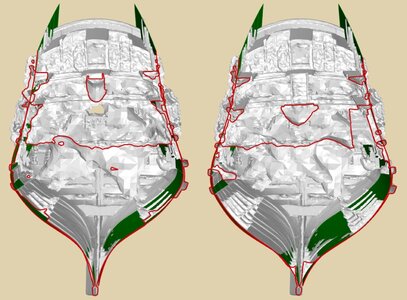
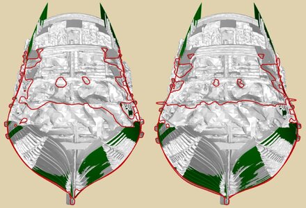
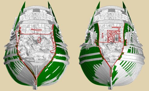
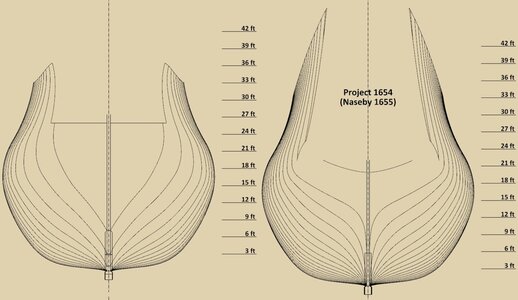
Below are a series of comparative cross-sections of the Ö 3 model together with the shapes reconstructed using historical methods.


01.jpg


02.jpg


03.jpg


04.jpg


05.jpg


06.jpg


07.jpg

.​
 
Last edited:
.​

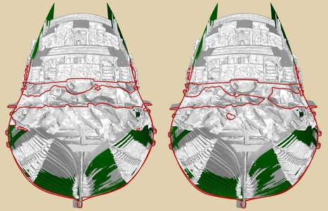
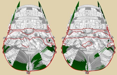
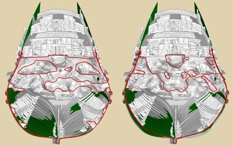
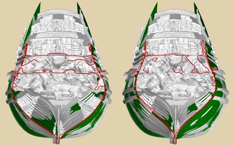
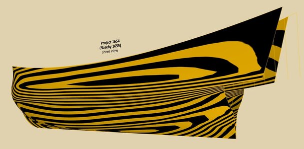
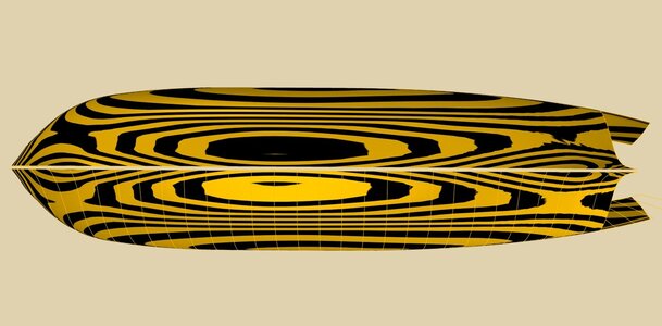
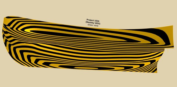
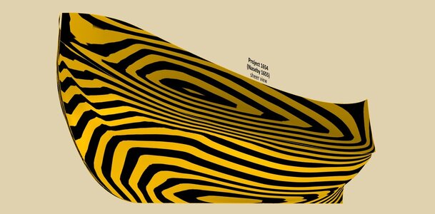
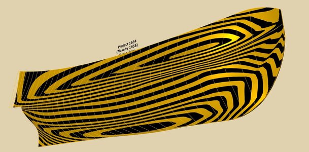
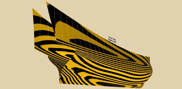
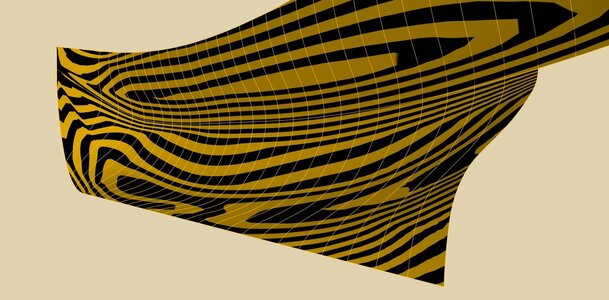
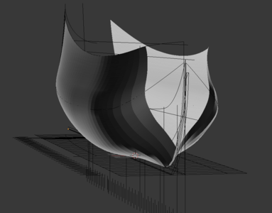
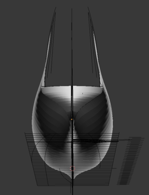
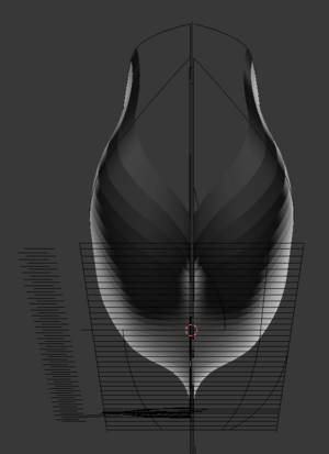
A few control shots using the zebra test to assess shape harmony. The more regular the stripes, the better. Only on the bow do they have a dodge, but this is due to the convergence of the lofted surface to very short line sections and is not dangerous here, being somewhat artificially introduced by the automatic surface lofting algorithm.


ViewCapture20230603_101218.jpg


ViewCapture20230603_101321.jpg


ViewCapture20230603_101344.jpg


ViewCapture20230603_101425.jpg

ViewCapture20230603_101522.jpg


ViewCapture20230603_101626.jpg


ViewCapture20230603_101814.jpg

.​
 
I am a follower of the amazing and unparalleled reconstruction taking place here. The iterative nature of this attempt (and the lack of 3D tools like those used by others) gave me an inspiration to recreate the Waldemar's drawings as a program script, which allows me to test different ratios and definitions of the rising and narrowing lines as presented in this thread. This is still a work in progress.
As an experiment I have tested and compared the propositions of a dilemma the discussion on which took place in the London's thread. The contemporary sources like the Deane's Doctrine and the manuscript from the 1620s provide a description which usually makes an impression of a constant radius floor sweep arcs. While putting the historical analysis aside I wanted to see a hull which has them varied or fixed. Here you can see these as well. The fixed radius produced a hull which has a drawback - the concave portions in the fore part.

FloorFixed.png

FloorVaried.png
 
.​

Many thanks Donatas for this entry. It begs for a longer commentary, but for now just a general conclusion that the shipwrights of the time must have seen this problem and certainly looked for remedies, at least those more advanced in their profession.

But it is necessary to at least add here that although Deane only described fixed radius sweeps, he had already drawn variable radius sweeps in his diagrams, without a word of explanation. Be that as it may, Deane's Doctrine 1670 was educational and was written at the request and use of a total layman in matters of design, Samuel Pepys, his promoter of high standing. It is hardly surprising, therefore, that it was a deliberately simplistic work.

.​
 
One more thing I found surprising is how valuable the underappreciated "pure geometry" sections of these treatises turn to be. And I believe this was valued by the authors of the day. One needs to constantly employ the Pythagorean solution to calculate sagittas, half-chords and radii.
 
Donatas, just the other day I wrote to Waldemar I imagined a program with similar functionality, to emulate a 17th century British shipbuilder, and here you wrote it!

And as a joke, I thought it could have been implemented (without the part of mesh generation, obviously) on contemporary technological level, as a complicated clockwork mechanism. Insert a paper sheet, check the numbers on input gauges, turn a handle for a couple of minutes, get an admiralty draught.
 
.​

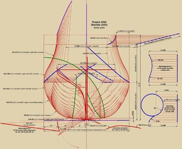
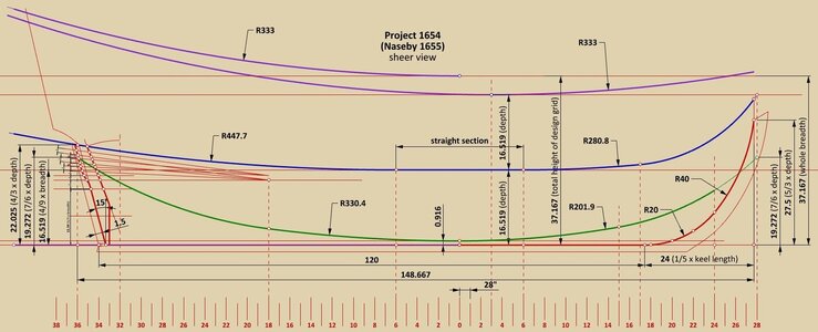
This is incredible! Even now, already in the final stages, I am still discovering various subtleties, so there still will be some updates in addition to new things. The most important of these revisions concerns the run of the two most important design lines (partially), specifically the rising line of the breadth fore, and the narrowing line of the floor aft. This is a rather unnecessary complication of the design by the original creator, because on the body plan (used ultimately to trace the contours of the frames, whether on mould loft or on paper), these particular parts give almost straight sections anyway, which would have made the work considerably easier and at the same time reduced the possibility of mistakes. But it's hard to argue with the artefact on this, or at least I don't intend to....

The overall impression is that in this project 'everything' is subordinated to obtaining the smoothest, most harmonious shapes possible, which has actually been expertly achieved, and this must be clearly emphasised - without the use of corrective diagonals and waterlines whatsoever! However, this came at the price of enormous design complexity for the underwater part.

Against this background, even the employed shape (in the sense of a specific geometrical construction) of the main design lines seems to be of secondary importance. For, paradoxically, a designer using such elaborate geometrical solutions for tracing the contours of the frames, applied only the two most simple, even primitive in the design sense, forms for these lines: mostly a composite of two arcs of a circle with the two exceptions of the simplest variety of mezzaluna. This state of affairs further confirms that the designer's main optimisation effort was focused precisely on obtaining smooth hull surfaces rather than other aspects.

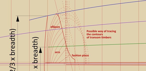
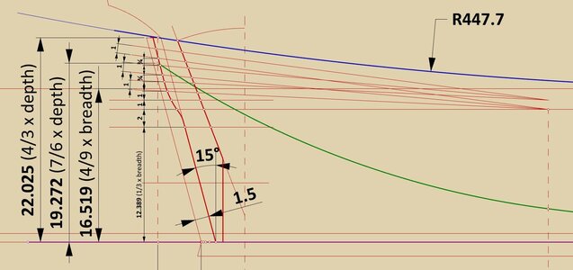
So, for those who are interested in the old ways of designing or reproducing these shapes, another set of the updated diagrams below.

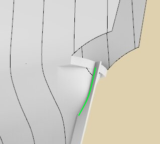
In addition to the changes indicated above, the diagrams have been supplemented by the fashion piece (constructed in the usual way), the contours of transom timbers (the upper ones are in the form of an ellipse, the lower ones in the form of circular arcs), also variable radii have been applied to the lower arcs of the hollowing curves aft.

ViewCapture20230607_124110.jpg


ViewCapture20230607_124008.jpg


ViewCapture20230607_124509.jpg


ViewCapture20230607_123425.jpg


ViewCapture20230607_125109.jpg
 
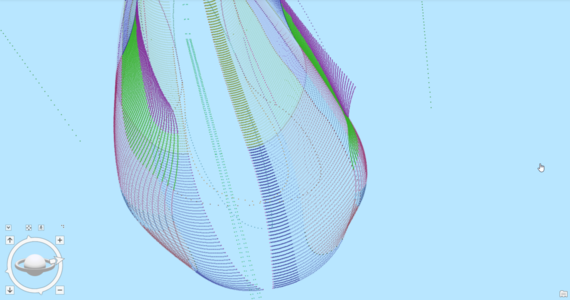
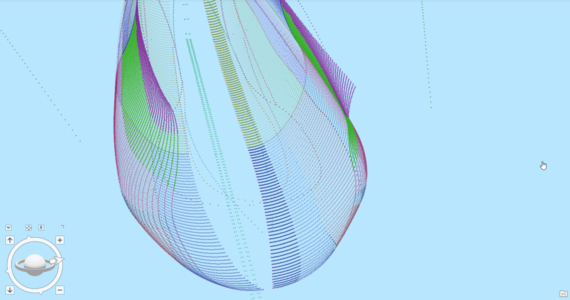
For very crude and graphical analysis I connect the hull lines with straight sections and then look for irregularities in their transition from one to another under different shading conditions:

1686218000408.png 1686218034369.png

1686218190297.png 1686218233401.png

The resulting mesh is almost ideally laddered - except for one place.

It happens around the lower breadth curves midship and affects to more or less extent stations 12, 14 and most of all 15, when a sudden break in the flow of vertices is visible:


1686218489588.png 1686218641437.png


The flaw is admittedly very small, and on a real scale would have probably be very easily (but manually) corrected.
 
.​

Thank you Martes for showing your assessment. Somewhat contrary to the introduction, the test he conducted is not "crude" at all, but very rigorous and unforgiving (the optical light test is used quite extensively even in precision mechanics), so I am satisfied with the result.
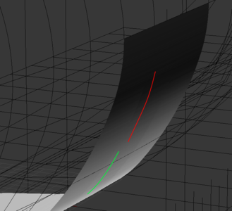
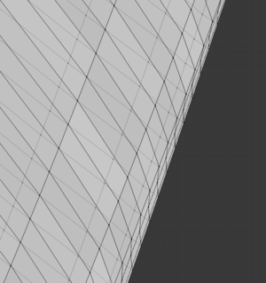
To be fair, Martes had already flagged up this problem in the midship area, and it does indeed exist. It cannot be completely eliminated, as it is caused by the straight section of the line of greatest breadth, and I could only minimise it by correcting the reduction devices accordingly. However, I am personally not sure that this was already done at the frame tracing stage, plus the lines of the model do not suggest this.

In addition, as Martes pointed out, in real scale it is at most a very few small millimetres, and considering the way the ship's skeleton was built at the time, by separately adding successive framing elements (futtock timbers, naval timbers, top timbers) and the auxiliary use of place-positioning wooden ribbands, such a waviness here could even have been self-corrected without any conscious intervention to that effect. As a result of all this, I have left it as it already is.

Thanks again Martes for your presentation.

.​
 
Thank you, Waldemar :)

I only referred to the test as relatively crude since it is very simple and does not allow to programmatically quantify the results in any way, but the precision is indeed very high. The distance between the actual place of the line in the faulty place of 15th station and the intended position measuring around 1/100 of a foot (1/8 of an inch, ~3mm), and it is still visible.

It is somewhat peculiar that while the author went to greatest geometrical pains to ensure the smoothness of surface run (and he did in all other places, incredibly so), he would leave such a inconsistency uncorrected, unless there was a standard practice of working with very close lines around the midship. So there probably was one.
 
Last edited:
.​

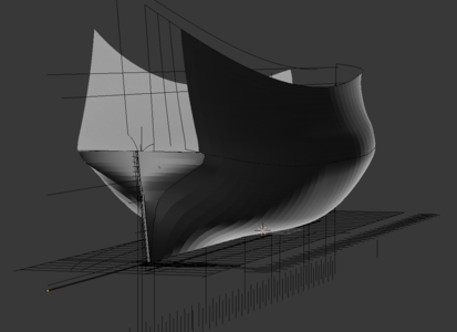
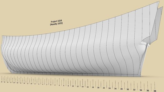
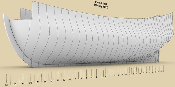
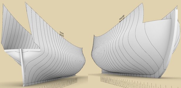
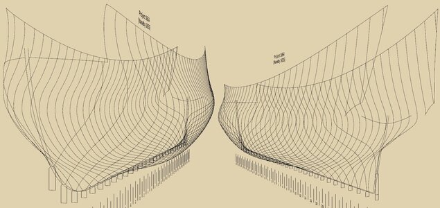
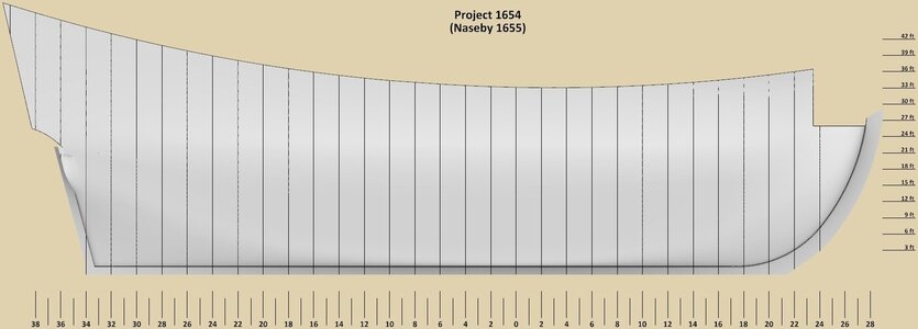
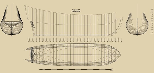
Thank you all for participating and watching this project, which I consider to be finished if there are no more questions or comments. To conclude, below are a few more renders and the reconstructed lines of the Ö 3 model in a modern convention.

Waldemar Gurgul

ViewCapture20230608_230242.jpg


ViewCapture20230608_230343.jpg


03.jpg


02.jpg


ViewCapture20230608_230914.jpg

ViewCapture20230608_231403.jpg


01.jpg

.​
 
.​

Oh yes, that could even be added quite easily, but the intention of the project was quite clear – it was to find the original method of designing the shape of the ship's hull, not to recreate every design or structural detail of any element of the model Ö 3. In this way I would have to develop complete plans for the model, taking into account all its elements, and this I leave to the eventual developers of such complete plans. They now have a fairly solid basis for such an undertaking, and I have other projects in mind.

.​
 
Last edited:
This has been a very satisfying conclusion to both your and Martes's efforts, Waldemar. As someone who is also interested in re-constructing highly plausible hull forms for mid to late 17th C. ships, your approach is both eye-opening and inspiring. Thank you both for taking the time to share this with the forum. Is it too early to ask what your next project might be?
 
Incredible work - thank you both @Waldemar and @Martes for your herculean effort in reverse engineering this 17th century wooden model.

Do you have a summary of your findings as to why you believe this model represents - the Naseby since earlier in this thread it was stated why it couldn't be?

I know along the way you've shared your thoughts on the subject along the way, but I thought a summary would put this projects findings nicely to bed since it is monumental.
 
.​

@Hubac’s Historian

Many thanks, Marc. Your eye-opening observation was particularly telling and I thank you for it. Indeed, I'm mostly trying to rely directly on source material and some of what I've written could be considered a challenge to the 'official' symposium versions, which I'm beginning to see as being somewhat stagnant and disappointing in this particular aspect, for various reasons.

The plan now is to revisit London 1656, specifically its extant simplified plan, and try to interpret it realistically with the information gleaned from the analysis of the Ö 3 model. But first I need to take a bit of a breather and distance, as this analysis has been quite intense...

.​
 
.​

@Allegheny

Thank you for your words of appreciation, Allegheny. To be honest, the primary objective of the project was to establish the method used to design the shapes of this ship model. Its identification, on the other hand, is somewhat derivative of this overarching objective and took place by accident, as it were. However, now that it has happened, I have to say that, given a choice between conclusions based on 'hard' information coming directly from the artefact, and today's interpretation based on other interpretations of today and yet based on vague and ephemeral criteria, there is no doubt in my mind what to choose.

.​
 
Back
Top