Hooray! - my IT friend has got me up and running again on word, so I can access the 'Natterer' articles again and re-post the parts that disappeared!
So here goes:
‘Natterer’ – A shipbuilding Odyssey? – Part 11
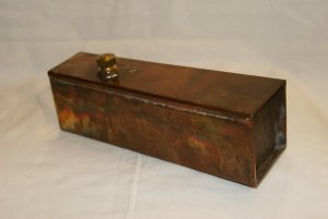
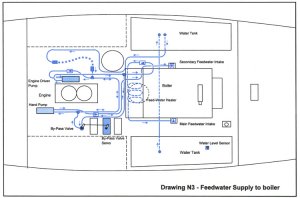
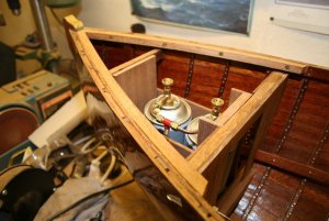
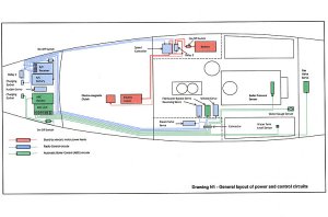
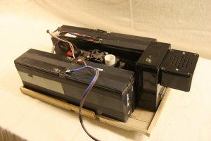
You will remember that I had decided to assemble the engine and boiler onto a baseplate, so I could remove the power-plant in one go. I had spent a lot of time and thought on exactly how I was going to control the engine and boiler, and in the end determined that the servos to control the reversing lever, boiler feed by-pass valve and whistle would all sit on the baseplate and come out with the power-plant. By dint of careful planning of pipework and placement of valves it was possible to get all the servos together in one block, which could then be hidden by the ubiquitous ‘wooden box’, with short connecting links coming out of the box to connect with the appropriate valves and levers.
The boiler also had to carry the boiler pressure temperature sensor, and the water level sensor, so in all that made five sets of leads coming off the power-plant. They all converged into the ubiquitous box, and were connected into the back of a “D” type 15 pin plug.
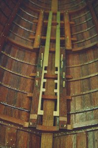
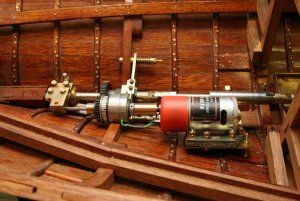
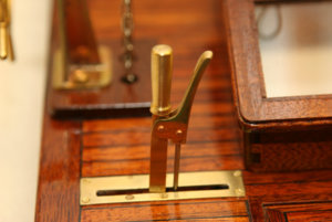
The steam throttle valve was a standard globe valve on the steam line from boiler to engine, and was so arranged that it engaged via a simple dog clutch onto the output from a sail winch servo, fastened into the structure of the hull. The sail winch then had a sufficient number of turns to fully open the globe valve.
So we now had a power-plant that would slide down into the hull, engage with the tapered pins previously mentioned, and then sit on the two studs, picking up the steam valve servo en route via the dog clutch. All I had to do was then plug in the electronics via the 15 pin plug, connect the drive to the propshaft and connect the water tanks via a quick-release coupling. Takes about a minute! (or two, and a lot of swearing if my thumb gets in the way)
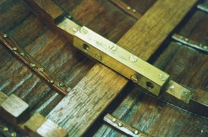
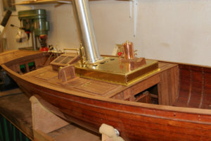
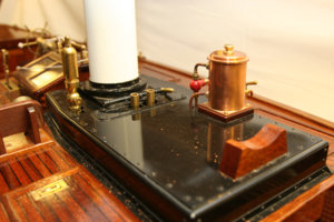
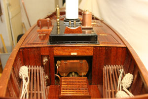
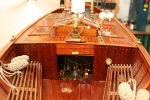
Reference to the photos should hopefully make the arrangement clear! (Or not, depending on the level of my erudition) The steam valve was arranged to end up in its own ‘locker’ on the hull, and be hidden by a removable lid. The second globe valve you can see in the same steam line is permanently fully open and is cosmetic, being visible through the engine room casing.
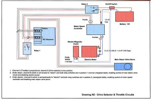
By now there were 6 servos, 3 sensors, 2 relays, a speed controller, an electro-magnetic clutch, an electric motor, a boiler control module, a receiver and various batteries floating around within the confines of the hull, all hoping to eventually meet up for fun and friendship, possibly leading to more. All the leads had to go somewhere, and this was under the decking at the stern.
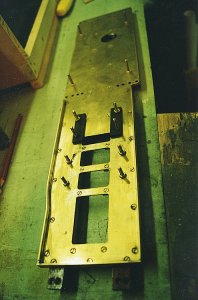
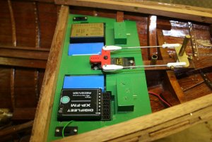
A mounting plate (green in the photos) was made up, holding the radio receiver, ABC Boiler Control System, their associated battery packs, and various on/off switches and charging sockets. I started with a Fleet radio system, purchased many years ago when I thought I was somewhere near finishing(!!!) However, since 2.4 has arrived on the scene, I’ve changed to that, mainly to avoid frequency clashes. I’ve used the Fleet outfit in other boats, as well as Natterer, and it is still going strong, having never let me down.
I fitted wooden channels with covers through each side of the rear cockpit to carry all the wires, running under the slatted seats, so the wiring is hidden.
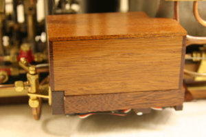
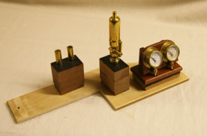
the 'ubiquitous box', hiding all the servos and connection block
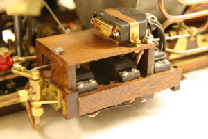
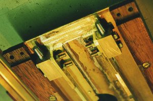
Sorry - slightly blurred, but it shows the 'ubiquitous box' with cover removed. Three servos power whistle, reversing lever and water by-pass valve; the blurry valve on the left.
15-pin 'D' plug on top.
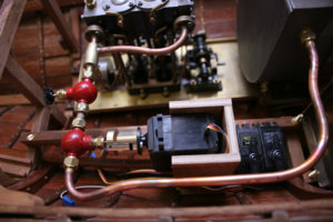
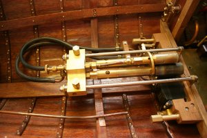
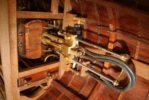
Steam valve driven by sail winch servo. The sail winch sits permanently in the hull, and engages with the steam valve via a dog clutch as the engine unit is dropped in. The whole lot is covered over with another box.
The second steam valve is a dummy, and can be seen from the cockpit.
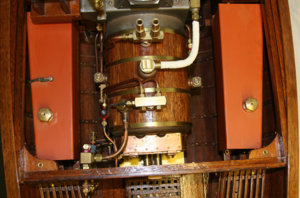
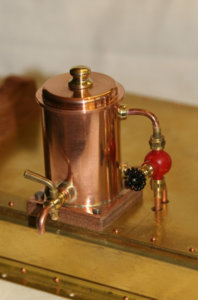
Boiler with water tanks to sides.
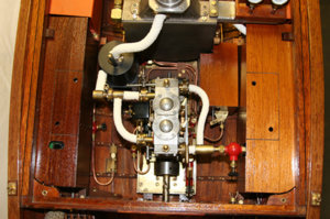
Engine with servos and controls hidden by boxes. or lockers.
The box/locker on the left hides the control gear for the emergency electric drive.
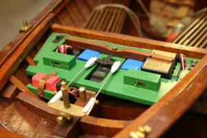
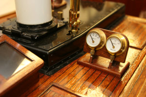
R/C equipment, with receiver, boiler control CPU, batteries, charging pins, rudder servo and R/C relay to change from steam to electric.
‘Natterer’ – A shipbuilding Odyssey? – Part 12
By this stage, I’d temporarily had enough of the mechanicals, and decided it was time to work on the decks and topworks. But since varnishing the hull, I’d been talking to a friend about the problems I was having with a vintage electric launch, constructed with similar sized planks to Natterer. Every winter, after a season on the river, she would dry out and the planks would shrink. The next season she would leak like a sieve until she took up again. My friend is very much in to model yachting and suggested I should try one of their techniques by glassing the hull on the outside. Apparently the model aircraft boys use this as well to cover the wings. Very wary about this, but decided to experiment on an old hull. I used a very fine glassfibre cloth, almost like a thin sheet of satin, draped over the hull and stippled through with resin. It becomes instantly see-through, and can be moved around to cover the contours of the hull. When dried, it can be further resined to cover any “starved” areas, and then polished to a high gloss. The finish is superb, with no seam lines, and in fact it is impossible to tell it is there other than on a sharp edge, which will end slightly rounded!
Anyway, I next tried it on the vintage launch and it was fantastic! No more shrinkage/leakage problems. So after a couple of seasons with the launch, and no ill effects, I took the bull by the horns and turned Natterer upside down before slavering paint stripper on all my nice varnish. (Yes – it took a lot of nerve!) When every last trace of varnish was off, I draped the cloth over her and started with the resin, working from the keel outwards. It was quite amazing the way the cloth could be moulded to the hull, and I found that one piece of cloth covered the whole hull in one go, with the only ‘seam’ being on the stem (which of course is covered by the brass stem piece. I seemed to be polishing for a week, but what a finish! Obviously, you couldn’t use this technique on a lot of scale boats, as the finish would be too high, but the steam launches were ‘big boy’s toys’ and generally finished to a very high standard, so quite acceptable.
I’m afraid no pictures for this stage (I was as nervous as h***, and forgot to take any!
So lets go straight on to the next part.
‘Natterer’ – A shipbuilding Odyssey? – Part 13
Anyway, on to the topworks. Natterer is flush-decked fore and aft, and also in the mid-section, over the power-plant, with fore and aft cockpits for crew and passengers.
Nothing particularly of note about the basic deck framework and planking, as it was all straightforward framing, albeit of quite large size. The planking on the mid-section was parallel, but that on the fore and aft decks was gently curved to follow the line of the gunwales, before being joggled into a kingplank on the centreline, and so had to be cut out of extra-wide stock. Black card was used on the planking edges to represent the caulking.
The gunwales themselves were a challenge, as they were 20 x 3mm in section and I wanted them in one piece from bow to stern. This entailed persuading them to follow the line of the gunwale, meaning they had to be curved in the plane of the minor axis (i.e. flat) This meant steaming, and a steam chest was rigged up using a length of copper pipe, well lagged, and a domestic wallpaper steam stripper to produce the necessary steam. The shape of the gunwale was transferred to the building board, and a series of blocks screwed down each side, which would enable the timber to be clamped in position after steaming. The gunwale was to be bent on a rather tighter radius to allow for the inevitable relaxation that would occur when the clamps were loosened.
The gunwales were steamed for about fifteen minutes, and then quickly transferred to the board, where myself and a friend clamped them up. Absolute poetry in motion, as the pair of us danced and wove around each other wielding wedges and hammers – actually a lot of tripping up, hitting of thumbs and even a few naughty words. When dry, they were released, and relaxed as anticipated to take up the required shape, before they were firmly screwed to infill blocks between the gunwale strake and the internal stringer. Job done!
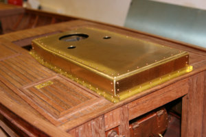
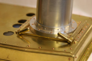
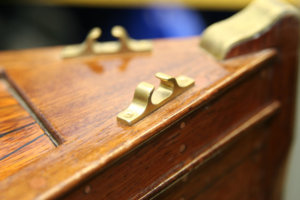
The remaining timber works on the deck included making access hatches in four locations, each with an inset brass lie-flat handle. No commercial items available at this sort of scale (if indeed at any scale) so they were hacked and milled out of brass sheet, and yes, they do work! There is a very pretty looking skylight over the engine so you can look at the whirly bits while they’re working (shades of looking at the engines on the Isle of Wight ferries when I was younger (
much younger)
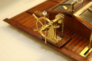
While making the handles for the hatches, I realised it was really quite difficult to envisage the size of fittings required, as with the odd scale of 1:4.5 the crew was going to be rather large – in fact the captain is 16” (400mm). The solution was to produce “George”, an articulated two-dimensional figure, which could be sat in the boat as necessary and enabled me to sort out seat heights, wheel sizes, reversing levers, Windermere Kettles and so on. Very useful, and I’ll use similar mock-ups while building any future boats.
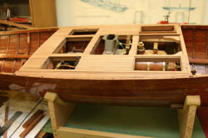
Centre section planked but not yet trimmed.
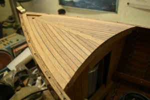
Foredeck under construction.
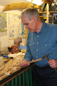
Yours truly bending the gunwales (still had some hair then!)
The solitary wing hanging on the wall serves to remind me -Always switch on the receiver before you launch!
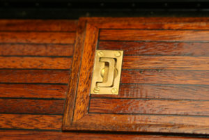
Recessed handle for deck hatch. Mixture of machining and hand filing - four of them!
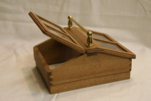
Engine room hatch - about 90mm square
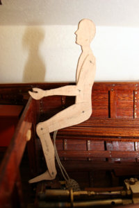
Fred - about 16" (400mm) tall
All for now- sorry if you have seen it before the site went down!
Ted


