• Win a Free Custom Engraved Brass Coin!!!
    As a way to introduce our brass coins to the community, we will raffle off a free coin during the month of August. Follow link ABOVE for instructions for entering.

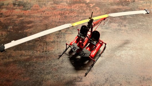
NHI Kolibri N-3, scale 1:48, scratch build

The past week and half or so saw the earlier swash plate assembly flying into the dustbin and the build of a new one.
Using both solder and CA didn't yield the results I wanted, worse, BOTH means of attachment resulted in too many parts being permanently attached to one another... :mad:
That led to the build of a new swash plate assembly with a slightly adjusted design. This required quite a bit of time, including redo's of some parts (again), but tonight I finished the rough build of the swash plate assy, including the pilot controls.
I now could tentatively fit the assembly to the rotor head and, even if I say so myself, it looks very promising. Still a few more details to add, apply top coats and then assembly time!

(I can't get this picture upright...)
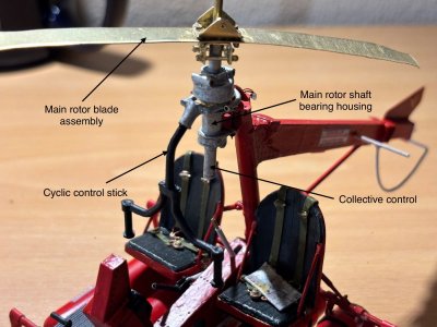
Overview with temporary install of the rotor shaft and the cyclic and collective controls.
View attachment 545243


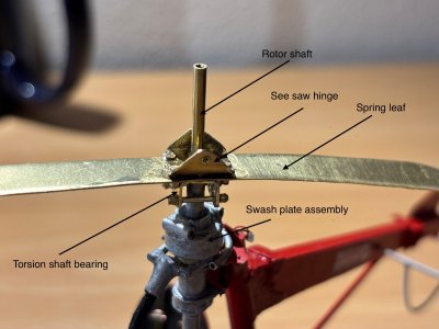
Detail view of the rotor head and controls.
View attachment 545236
Man-O-Man ……. When it is in your head and you made your sketches ….. then there is a solution. This looks so nice, Johan.
Regards, Peter
 
Man-O-Man ……. When it is in your head and you made your sketches ….. then there is a solution. This looks so nice, Johan.
Regards, Peter
Wow! So impressive from conception to execution!
Marvellous! You are really at the edge of the impossible.
Johan, my dear friend
amazing job, so accurate
What they all say Johan. Brilliant. Cheers Grant

Thanks again for your compliments!
Very early on in the build I committed to provide working flight controls and with every step I take, I question the wisdom of that decision.
It requires a lot of planning, understanding the function of all components and being able to simplify the design to allow the scale down to 1:24 and I can honestly tell you: it ain't easy... And at the same time I simply cannot turn back on my earlier decision until I'm proven wrong: that hasn't happened yet.
In all honesty: I'm exploring the boundaries of my capabilities.
 
I finally found time to start with the next subject: the main rotor.
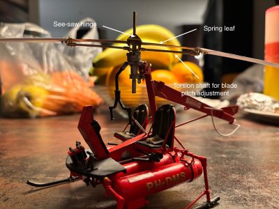
The main rotor consists of a central spring leaf package with a see saw hinge, two rotor blades and two ramjets at the rotor blade tips, plus the cyclic and collective flight controls and the fuel and ignition systems.
I know, the flight control system on the rotor mast is not complete yet, but I need the main rotor assembly before I can complete the control system.
The focus was on the manufacturing if the see-saw hinge and the inner bearing of the two torsion shafts (more on those later).
I made the spring leaf of a single strip of brass, t=0,3mm. I originally went for a thickness of 0,5mm but that appeared to be too stiff. The true spring leaf was composes of a leaf package of a number of spring leafs. At first I was inclined to replicate that idea, but the single 0,3mm leaf gives me the elasticity I need.

Below two pictures of the current status.


IMG_1323.jpeg

IMG_1322.jpeg
 
I like the paint scheme of the swash plate on down, sort of a galvanized appearance. To have all that detail in the space of a thumb nail is just incredible.
I fully agree with Daniel that ‘a bit of paint’ makes a big difference. And again some nice details on the rotor.
Regards, Peter
Both your remarks on the "bit of paint" made me think why paint does make such a huge difference?
I truly enjoy figuring out how things work, how I can believably simplify and scale down complex systems and figuring out how I can even make and assemble the parts.
While working at either of these stages I almost never have the need to put on any finish, but... As soon as an assembly has been more or less successfully completed, I can't wait to apply its finish.
So why is that finish so important? I can think of at least two reasons, 1) any manufacturing process leaves its mark and it ain't always pretty, so after some sanding and smoothing, it's time to paint, but more importantly 2) a well chosen paint scheme allows one to focus on various visible details. An unpainted model, constructed mainly from the same material, requires immediate and absolute attention,without being able to focus on a specific region. The finished model, with a balanced and matching paint scheme allows the viewer to enjoy a specific detail, before switching focus to another noteworthy detail.
That's why I think that "bit of paint" makes such a difference.
 
Quite a milestone has been reached! Both rotorblade halves have been successfully fabricated.
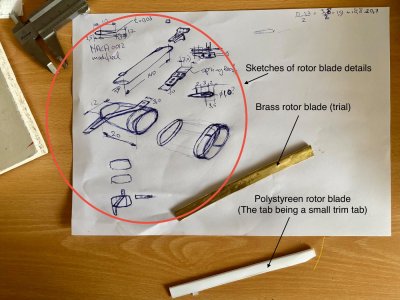
Before being able to produce usable parts, I experimented with brass sheet (t=0,3mm/0,012"). Although I used a demi hard brass, the material is way to stiff to get an acceptable part. One might wonder why I used brass in the first place, well, the answer is pretty simple; most parts of this build are made from brass and I simply didn't consider anything else until...
I still had some polystyreen sheet lying about with a thickness of 0,25mm/0,01" and polystyreen rod,dia 1mm/0,04". Strips of 140mm/5,52" long and 30mm/1,2" wide. I folded the strip at 10mm/0,4" from the edge and bonded the rod in the fold, then bonded the trailing edge and cut away the excess material.
It was way easier than I anticipated.
The first steps of the rotor blade assemblies were complete by adding the fittings, attaching the blades to the leaf spring, and the bearing bracket for the torsion shaft.

Some sketches and the first attempts at rotor blade fabrication:
IMG_1406.jpeg

Close up of (temporary) blade installation:IMG_1417.jpeg

Both blades temporarily installed. The small clamps are dummy ramjet installs.
IMG_1416.jpeg
 
Quite a milestone has been reached! Both rotorblade halves have been successfully fabricated.
Before being able to produce usable parts, I experimented with brass sheet (t=0,3mm/0,012"). Although I used a demi hard brass, the material is way to stiff to get an acceptable part. One might wonder why I used brass in the first place, well, the answer is pretty simple; most parts of this build are made from brass and I simply didn't consider anything else until...
I still had some polystyreen sheet lying about with a thickness of 0,25mm/0,01" and polystyreen rod,dia 1mm/0,04". Strips of 140mm/5,52" long and 30mm/1,2" wide. I folded the strip at 10mm/0,4" from the edge and bonded the rod in the fold, then bonded the trailing edge and cut away the excess material.
It was way easier than I anticipated.
The first steps of the rotor blade assemblies were complete by adding the fittings, attaching the blades to the leaf spring, and the bearing bracket for the torsion shaft.

Some sketches and the first attempts at rotor blade fabrication:
View attachment 550270

Close up of (temporary) blade installation:View attachment 550271

Both blades temporarily installed. The small clamps are dummy ramjet installs.
View attachment 550272
That is looking wonderful, Johan. Each material has its pros and cons and in scale with an extra challenge. The little bit of sagging looks very realistic.
Now is already a spider-chopper.:)
Regards, Peter
 
Quite a milestone has been reached! Both rotorblade halves have been successfully fabricated.
Before being able to produce usable parts, I experimented with brass sheet (t=0,3mm/0,012"). Although I used a demi hard brass, the material is way to stiff to get an acceptable part. One might wonder why I used brass in the first place, well, the answer is pretty simple; most parts of this build are made from brass and I simply didn't consider anything else until...
I still had some polystyreen sheet lying about with a thickness of 0,25mm/0,01" and polystyreen rod,dia 1mm/0,04". Strips of 140mm/5,52" long and 30mm/1,2" wide. I folded the strip at 10mm/0,4" from the edge and bonded the rod in the fold, then bonded the trailing edge and cut away the excess material.
It was way easier than I anticipated.
The first steps of the rotor blade assemblies were complete by adding the fittings, attaching the blades to the leaf spring, and the bearing bracket for the torsion shaft.

Some sketches and the first attempts at rotor blade fabrication:
View attachment 550270

Close up of (temporary) blade installation:View attachment 550271

Both blades temporarily installed. The small clamps are dummy ramjet installs.
View attachment 550272
Bravo Johan. Baai baai mooi. Cheers Grant
 
Quite a milestone has been reached! Both rotorblade halves have been successfully fabricated.
Before being able to produce usable parts, I experimented with brass sheet (t=0,3mm/0,012"). Although I used a demi hard brass, the material is way to stiff to get an acceptable part. One might wonder why I used brass in the first place, well, the answer is pretty simple; most parts of this build are made from brass and I simply didn't consider anything else until...
I still had some polystyreen sheet lying about with a thickness of 0,25mm/0,01" and polystyreen rod,dia 1mm/0,04". Strips of 140mm/5,52" long and 30mm/1,2" wide. I folded the strip at 10mm/0,4" from the edge and bonded the rod in the fold, then bonded the trailing edge and cut away the excess material.
It was way easier than I anticipated.
The first steps of the rotor blade assemblies were complete by adding the fittings, attaching the blades to the leaf spring, and the bearing bracket for the torsion shaft.

Some sketches and the first attempts at rotor blade fabrication:
View attachment 550270

Close up of (temporary) blade installation:View attachment 550271

Both blades temporarily installed. The small clamps are dummy ramjet installs.
View attachment 550272
looking wonderful, Johan
 
What an amazing build Johan! The mechanics of the rotor head are already complex enough, but this craft adds fuel delivery to the mix! That, I assume, must come up through the very center of the shafts and must then split to each engine at the apex. Throttle must be from a single fuel control valve as I can't see how you could have two lines in a rotating mast (perhaps it is possible, I don't know.) I also can't see how there could be any electrical feedback to the instrument panel, so engine speed must have been controlled "by ear". Daring men in those days!
 
Back
Top