ANOTHER ONE FOR ME ON THE DAGGER BOARD CASE/DAGGER BOARD THE INSTRUCTIONS SHOW MAKING SOME FITTINGS AT THE TOP OF DAGGER BOARD BUT VERY LITTLE DETAILS CAN YOU HELP. GOD BLESS STAY SAFE YOU AND YOURS DON
-

Win a Free Custom Engraved Brass Coin!!!
As a way to introduce our brass coins to the community, we will raffle off a free coin during the month of August. Follow link ABOVE for instructions for entering.
-

PRE-ORDER SHIPS IN SCALE TODAY!
The beloved Ships in Scale Magazine is back and charting a new course for 2026!
Discover new skills, new techniques, and new inspirations in every issue.
NOTE THAT OUR FIRST ISSUE WILL BE JAN/FEB 2026
You are using an out of date browser. It may not display this or other websites correctly.
You should upgrade or use an alternative browser.
You should upgrade or use an alternative browser.
Norwegian Sailing Pram - (Modelshipways)
- Thread starter RodneyB
- Start date
- Watchers 11
-
- Tags
- model shipways
The top of the daggerboard is basically made up of four pieces. Two are made from the 3/32" stock that is provided. I cut each a little longer than the dagger board case. The hardest part for me was creating the finger grips. I think the instructions say to do it after you glue them to the side of the daggerboard, but I did them first. After doing that it would likely have been easier to do it after they are attached. They get glued to the top centered on the daggerboard and flush on top, but I didn't do that yet.
If you picter these long pieces on the side there is a gap between them. That's where the piece of 1/16" scrap comes in. This comes from a piece of the laser cut the dagger board was in. I cut them the width of the 3/32" pieces using them as the a template. They are just long enough to fit the overhang of the side pieces.
With all four pieces cut, a little oversized, I glued the first side piece on making sure it was centered and flush on top. Then I glued the two 1/16" pieces on either side of the dagger board on the part of the 3/32" piece that is hanging over on either side. I let all that dry and then made sure the At this point I made sure the side that hadn't had the 3/32" piece glued on and sanded the 1/16" pieces flush with the daggerboard. Then I glued on the last 3/32" piece.
At that point you have a sandwich with the daggerboard and 1/16" pieces in the middle. Then I sanded the top flush, and the ends to the appropriate length of the daggerboard case. If you haven't created the finger grips now would be the time.
That's a lot of typing to say you glue four pieces to the daggerboard.
I hope that all makes sense.
Rodney
HI ROD AGAIN A QUESTION FOR YOU BEEN THINKING OF SOMETHING FOR A WHILE THE INSTRUCTIONS SHOW WHAT THE THWARTFRAMES A THRU E ACCORDING TO TEMPLETE IF THAT IS CORRECT YOU CAN NOT FIT THE SEATS YOUR PICTURE SHOWS ONLY ONE WHITCH SEEMS TO BE CORRECT ANY HELP ON THIS WOULD BE APPRECITED. GOD BLESS STAY SAFE YOU AND YOURS DON
I'm not exactly sure I follow exactly what your asking. But post 17 on Nov. 23, shows the exact placement pretty clearly. This link should take you there. If that doesn't clear up your question let me know and I'll try better. The only issue I had was the thwarts were too wide. I had to sand them a little to fit down on the frames.HI ROD AGAIN A QUESTION FOR YOU BEEN THINKING OF SOMETHING FOR A WHILE THE INSTRUCTIONS SHOW WHAT THE THWARTFRAMES A THRU E ACCORDING TO TEMPLETE IF THAT IS CORRECT YOU CAN NOT FIT THE SEATS YOUR PICTURE SHOWS ONLY ONE WHITCH SEEMS TO BE CORRECT ANY HELP ON THIS WOULD BE APPRECITED. GOD BLESS STAY SAFE YOU AND YOURS DON
OK I SEE IT NOW GOT IT, SOMETIMES IT TAKES ME A WHILE TO GET IT RIGHT, THANK YOU SO MUCH. GOD BLESS STAY SAFE YOU AND YOURS DON
Glad I could be of some help. I need to get busy and finish. I have the mast ready to go on, but I've been focusing on my Bluenose.
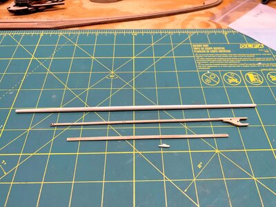
I found some time to work on this in between other projects. One thing I wanted to try was creating the mast as described in the instructions by gluing two strips together and planing and sanding to get the round shape. This turned into a long drawn out disaster and I ended up with more an oval than a round mast. I'm sure it had nothing to do with the technique described, but my implementation. I still needed a mast, so I popped the dowel provided in my drill press and sanded it quickly to shape. (I spent an hour or two on the suggested method, and about 10 minutes at the drill press.)
Once satisfied with the shape of the mast, I turned my attention to the boom. Since this was already pre-laser cut it was flat, but again I popped it in the drill press and in a matter of minutes had a reasonable result. The issue I ran into was with the gaff. It's a laser cut piece like the boom, but is narrower than the piece is thick, so you're starting with a rectangle, not a square. Where this becomes an issue is there are a number of pre-drilled holes along the length. The problem I ran into is if I had sanded it down until completely round the holes would be wider than the stock. that doesn't work. So it's still a bit oval as I didn't want to remove any more.
All-in-all the result is okay. I also had to make a new cleat as I managed to lose the original laser cut part. That still needs to be shaped a little.

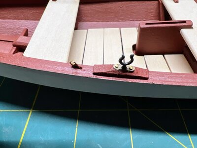
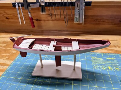
Today I started on the sails. The final phase of the project. The masts are ready to be placed. The oarlocks have be placed, although the kit only include two not the four that were supposed to be there. Of course I should have checked when I opened the kit, but didn't so now I'm waiting for Model-Expo to send the two missing parts. Since it took nearly two weeks for them to respond to my request I'm not holding out hopes that they will arrive quickly.
Here's a shot of the oar locks that were included.

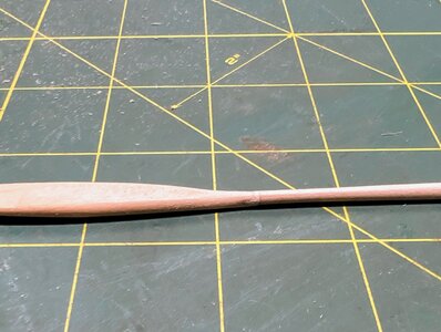
I also finished the oars. Had the misfortune of snapping one in half, but was able to place a pin between the two parts and it looks acceptible. I'm not thrilled, but it looks acceptable.

Here's a shot of the oar locks that were included.

I also finished the oars. Had the misfortune of snapping one in half, but was able to place a pin between the two parts and it looks acceptible. I'm not thrilled, but it looks acceptable.


