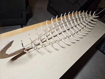
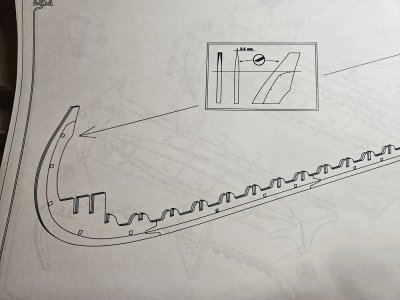
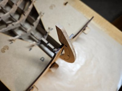
Oseberg - Ver. 3 - Pavel Nikitin - 1:25

Frames (cont'd)

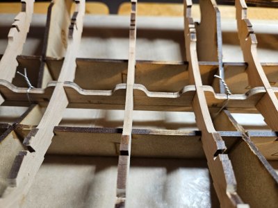
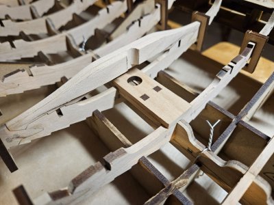
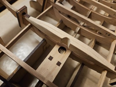
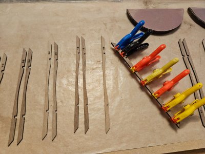
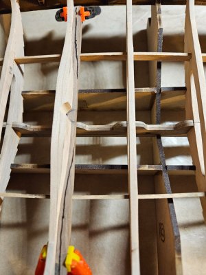
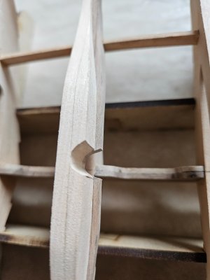
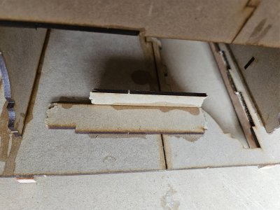
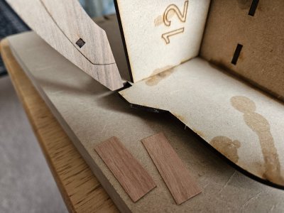
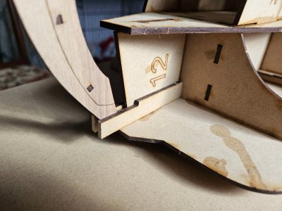
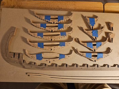
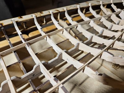
Work continues on the Oseberg's frames. Once the main frames had dried, it was time to clean up the fit between the thwart and the frames. Reversing the thwart helped by reverse-matching the char bevel, but it wasn't as close a fit as I would like. The zig-zaggy joint between the two made the job challenging. Taking off just a little too much in one spot opened up a gap in another. Just be careful and with needle files, use a light touch with lots of test fitting. The thwarts were then taped on to keep them with their respective frame. Then I beveled the notches that receive the strakes to the guidelines engraved on the ribs. The closer you get to the stems, the steeper the bevel and the more you have to slant that bevel upwards. There are also notches (covered up with tape here) where a stringer passes through for the full length of the hull on each side. I made sure the stringer fit with the thwart on.
20250118_195540.jpg

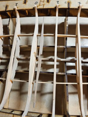
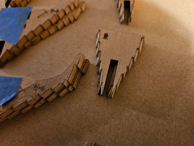
On the smaller frames, I used a knife to cut in the upwards facing angle and then files and sanding sticks to bevel the edges. There will no doubt be some adjustment needed as I fit the strakes.
20250118_195606.jpg

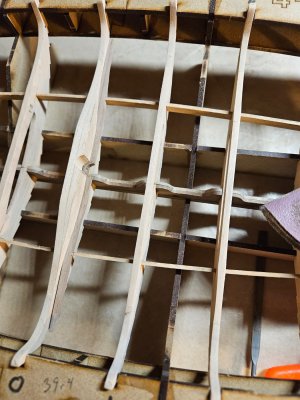
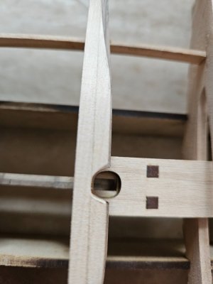
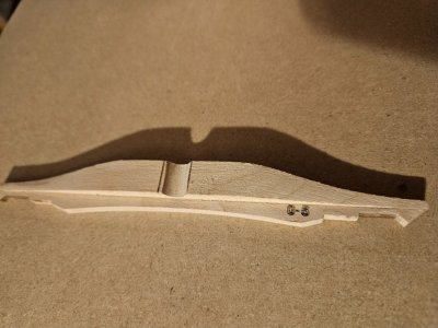
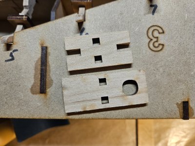
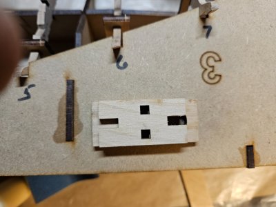
The only single frame is the center one. Its thwart has a doubler glued on with a circular notch facing astern to support the mast. There is a paper template supplied to locate the notch and to taper the doubler.
20250119_193142.jpg

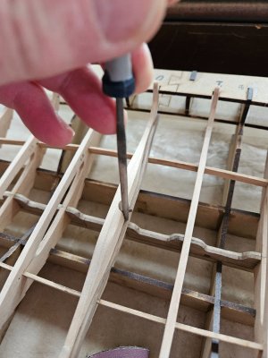
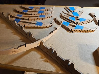
The next step is to fit the frames to their respective slots in the keel. Holding the thwart in place, I block-sanded the faces of the frames and thwarts. The keel is symmetrical, but I marked the ends for bow and stern. As I adjusted the notches in both the keel and the frame, I marked each frame and it's respective thwart with (B)ow and (S)tern.
20250118_203124.jpg

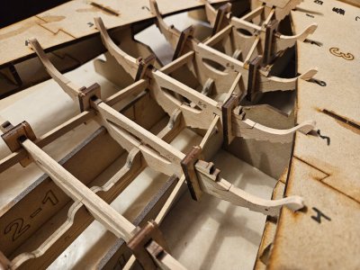
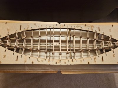
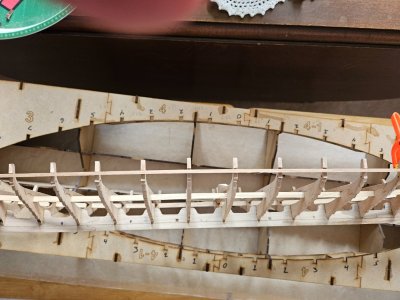
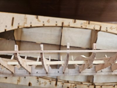
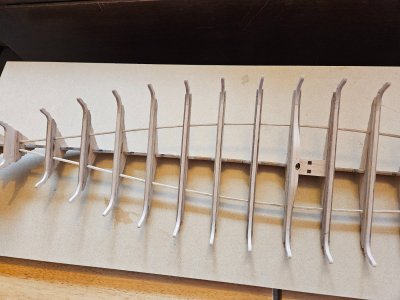
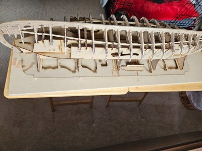
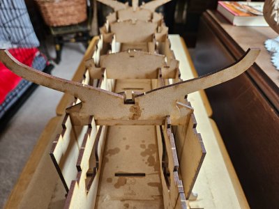
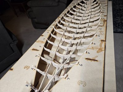
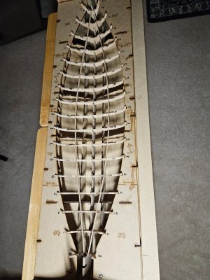
Once each frame was fitted to its respective slot in the keel, it was time to test the fit in the jig. I marked up the jig for bow and stern as well as the frame numbers. The only notches in the jig that needed widening were for the keel along the bottom. I also beveled the bottoms of the long notches where the stems rest. The stringers are visible in the next photos.
20250119_184038.jpg

20250119_184021.jpg
20250119_184052.jpg20250119_184149.jpg

The next step will be go take everything apart and glue the frames to the keel in the jig. Not tonight. Sleep
 
Frames (cont'd)

Work continues on the Oseberg's frames. Once the main frames had dried, it was time to clean up the fit between the thwart and the frames. Reversing the thwart helped by reverse-matching the char bevel, but it wasn't as close a fit as I would like. The zig-zaggy joint between the two made the job challenging. Taking off just a little too much in one spot opened up a gap in another. Just be careful and with needle files, use a light touch with lots of test fitting. The thwarts were then taped on to keep them with their respective frame. Then I beveled the notches that receive the strakes to the guidelines engraved on the ribs. The closer you get to the stems, the steeper the bevel and the more you have to slant that bevel upwards. There are also notches (covered up with tape here) where a stringer passes through for the full length of the hull on each side. I made sure the stringer fit with the thwart on.

View attachment 496270

On the smaller frames, I used a knife to cut in the upwards facing angle and then files and sanding sticks to bevel the edges. There will no doubt be some adjustment needed as I fit the strakes.

View attachment 496271

The only single frame is the center one. Its thwart has a doubler glued on with a circular notch facing astern to support the mast. There is a paper template supplied to locate the notch and to taper the doubler.

View attachment 496272

The next step is to fit the frames to their respective slots in the keel. Holding the thwart in place, I block-sanded the faces of the frames and thwarts. The keel is symmetrical, but I marked the ends for bow and stern. As I adjusted the notches in both the keel and the frame, I marked each frame and it's respective thwart with (B)ow and (S)tern.

View attachment 496273

Once each frame was fitted to its respective slot in the keel, it was time to test the fit in the jig. I marked up the jig for bow and stern as well as the frame numbers. The only notches in the jig that needed widening were for the keel along the bottom. I also beveled the bottoms of the long notches where the stems rest. The stringers are visible in the next photos.
View attachment 496292

View attachment 496291
View attachment 496293View attachment 496294

The next step will be go take everything apart and glue the frames to the keel in the jig. Not tonight. Sleep
Looking good, very nice job!
 
Nice joinery on the frames. The notches on the frames for the clinker-built strakes look very crisp and clean. I'll keep watching Congrats.
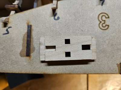
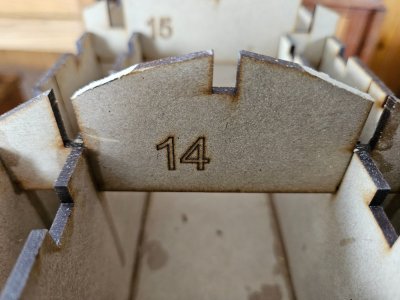
Thank you Alex. I have to say that it has always bugged me to see the part numbers left on the parts. These were engraved deep enough that to sand them off would have changed the thickness of the frames enough to make the fit in the keel a bit sloppy, so I decided to leave them. Sigh. I would much prefer to have the part numbers engraved next to the part, rather than on it. That way I could mark it myself in an area that I know will not ever show.

Looking good, very nice job!
Thank you @brickman61.
 
Russ,
I agree with you, although I often write the part number with a soft pencil on the part itself when there are a lot of parts; I erase and/or sand it later. Pavel uses a dark varnish/stain on his ships. I wonder if the dark stain would hide the numbers ?
Alex R
 
Russ,
I agree with you, although I often write the part number with a soft pencil on the part itself when there are a lot of parts; I erase and/or sand it later. Pavel uses a dark varnish/stain on his ships. I wonder if the dark stain would hide the numbers ?
Alex R
Well, so far anyway, the parts with numbers burned into them are all hidden inside the hull. This is fine, unless you plan on doing a cut-away or leaving some floor planking off. Since the frames, while similar to the original, are not constructed exactly like the original, I won't be doing that.
 
Frames (cont'd)

Before I get back into the frames, I should mention one thing. In the instruction manual, Pavel shows the upper portion of each stem to be tapered prior to attaching the frames. In his video, however, he does not taper them yet. My guess is to prevent possible damage to the thin edge while handling the boat and to wait until the outer stem pieces are attached. I decided to follow his lead and leave them until later.

20250120_185014.jpg
20250120_184908.jpg

The keel did not sit at the bottom of the two innermost jig members, so I cut small notches in the bottom of the jig and used some wire to pull the keel down. I wanted everything as rigid as possible for gluing in the frames.

20250120_191157.jpg

So now it's time to attach the frames to the keel, followed by the two stringers and the thwarts. I mused for awhile on just how I was going to effectively clamp the thwarts. I pulled up Pavel's next video and discovered that he has provided a clamping method in the kit. This is not documented anywhere in the instructions or drawings. Tip - watch his videos!

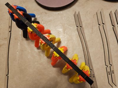
He provides some rectangular loops and wedges to apply pressure to each end of the thwarts.

20250120_183104.jpg
20250120_183417.jpg
20250120_183810.jpg

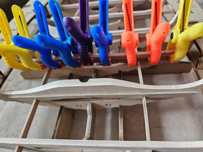
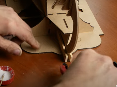
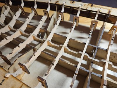
Brilliant! Okay, now I can glue the frames onto the keel within the building jig. Glue is applied, then you hang a clamp on each end of the frame before placing the frame on the keel. Be sure that the clamp sits outside the inner longerons of the jig on the endmost frames as you won't be able to get it past the longeron afterwards. Pavel actually made this mistake and had to pull a partially set frame from the keel and reposition the clamp.
20250120_200153.jpg

Next is the mast step. It comes in two pieces and straddles the keel aft of frame 0 (the center one). The two pieces are glued together and then secured with square pegs.

20250120_201742.jpg

Be careful here, because the smaller part is slightly asymmetrical. It needs to be attached to the underside of the larger piece so that there is an equal amount of overlap on each end when the peg holes are aligned.

Wrong...

20250120_201710.jpg

Correct...

20250120_201732.jpg

This is then placed on the keel on the aft side of frame 0 with no glue. ?? Don't know why, but Pavel didn't glue his in either ... yet. I took the opportunity to adjust the radiused furrow in the thwart doubler to match the hole in the mast step.

20250120_202036.jpg

That's it for today.
 
Last edited:
Frames - Thwarts

Gluing the thwarts to the frames was pretty straight-forward, primarily because I took the time earlier to make sure each one fit its respective frame as closely as possible. I also made sure that the stringer fit properly in its slots. The slots are a loose fit because the stringer passes through them at an angle as it curves around. Only a couple were too snug and had to be adjusted.

The clamps that Pavel provides worked pretty well, but were a bit fiddly at times. Getting the clamp at just the right spot and angle so that there was just the right amount of gap in the slot was tricky on some frames. Pavel provided plenty of the wedges with little grip knobs as well as some smaller wedges (which I didn't need to use), because I had to double or triple up the wedges on some clamps.

20250123_175759.jpg
20250123_175815.jpg
20250123_175840.jpg

Once the glue dried, I removed the frame from the jig ... okay, I have to stop for a minute here. Pavel calls his jigs "slipways". Yes, it's important to use the proper nautical terminology for our parts as we build ships, but really? A slipway is defined as:

slipway (plural slipways)
(nautical) A sloping surface, leading down to the shore or to a river, on which ships are built, repaired or stored and from which they are launched.

whereas a "jig" is defined as:

jig (plural jigs)
A device in manufacturing, woodworking, or other creative endeavors for controlling the location, path of movement, or both of either a workpiece or the tool that is operating upon it. Subsets of this general class include machining jigs, woodworking jigs, welders' jigs, jewelers' jigs, and many others.

Yes, we're building a boat on it, but it's nowhere near the water, is not sloping and the boat won't be launched from it. What we have here folks is a jig. (climbing down off my soapbox now) ;)

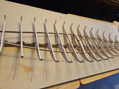
Moving right along ... once the power frame had been removed from the jig, I sighted down the length of it and noticed one of the frames was higher than the others, but just on one side. Most of the others were pretty well aligned. This can be seen using a batten in the following photos:

This side is not too bad...

20250124_115602.jpg

This side, not so much...

20250124_115750.jpg

It's very difficult to control this as you build, because the stringer, being tightly trapped between the frames and the thwarts, is going to pull the frame wherever it wants, depending on the accuracy of the placement of the stringer slots.

All I could do at this point was sand down the top of the offending frame to fair up with the others. As I add the planking strakes, I will no doubt have to shim the bottom of the frame to build it out so that it's fair. Other adjustments will have to be made as I progress with the planking as well.

I then sanded the faces of the frames where they would be visible to clean up the glue joints at the thwarts and to prepare for gluing on the next parts.

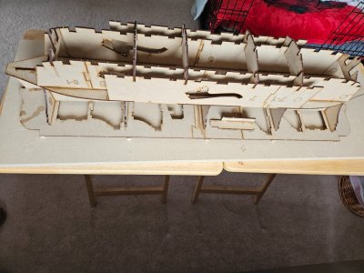
The power frame to this point:

20250124_165833.jpg
 
Beams

Pavel uses the term "beams" for the cross pieces on which the deck planks rest. I don't know what the proper Norwegian term for them is (I've looked), but I would consider them to be ledges rather than beams, however, I will go with "beams" for lack of a better term. I'm open to correction by those more knowledgeable.

There are two beams for every thwart except the two at the stems, where there is only one, and the center thwart of which there are four. Here is another instance where it is necessary to watch Pavel's video in order to see how the center beams are built. The notches in the bottom of each beam fit over the stringers.

Here's the general layout for the beams:

20250124_173825.jpg

And an up-close look at the center ones:

20250124_173845.jpg

Notice that the center beams are made up of a single one on the bow side of the thwart with a lamination of three pieces aft. These three must be glued together first. Then the top edge must be levelled and sanded enough so that it tucks under the thick thwart.

20250124_175355.jpg
20250124_175404.jpg

Once you can get it under the thwart, you must draw guidelines that follow the curve of the thwart, leaving the width of one beam proud to allow the deck to rest on it.

20250124_194643.jpg

Notice I have remove the unglued mast step for clarity and to give myself room to work. The beam is then shaped to the guidelines. I took as much of the mast relief out as I dared, but going all the way to the line would have made the beam too fragile to work with, if not cut all the way through.

20250124_200651.jpg
20250124_200703.jpg

Once glued in, I use a round-faced file and sandpaper around a thin dowel to work the mast relief groove back to match the thwart:

20250125_123406.jpg
20250125_124832.jpg
20250125_125248.jpg

Finally, working alternately from bow to stern and skipping every other frame, I glued each beam in place - one side at a time. I would advise against trying to glue both sides on at the same time, as you're likely to have them creep up or shift with the pressure of the clamps. As it is, you need to make sure your clamps are not tilted or cocked in a way that would shift each single beam. I usually had 3 or 4 beams clamped up at a time, then I would remove the clamps from the first one, clean up any glue squeeze-out while it was still rubbery, and then clamp another.

20250125_133817.jpg

It took the better part of the afternoon, but they are all finally on.

20250125_151032.jpg

The power frame is complete, now on to the second jig.
 
Whoa, hard to bend my mind around what you've done so far. The "stringer alignment" problems is interesting. Is partly because of the way the power frame fits into the jig (AKA slipway)??

Jan
 
Beams

Pavel uses the term "beams" for the cross pieces on which the deck planks rest. I don't know what the proper Norwegian term for them is (I've looked), but I would consider them to be ledges rather than beams, however, I will go with "beams" for lack of a better term. I'm open to correction by those more knowledgeable.

There are two beams for every thwart except the two at the stems, where there is only one, and the center thwart of which there are four. Here is another instance where it is necessary to watch Pavel's video in order to see how the center beams are built. The notches in the bottom of each beam fit over the stringers.

Here's the general layout for the beams:

View attachment 497614

And an up-close look at the center ones:

View attachment 497615

Notice that the center beams are made up of a single one on the bow side of the thwart with a lamination of three pieces aft. These three must be glued together first. Then the top edge must be levelled and sanded enough so that it tucks under the thick thwart.

View attachment 497617
View attachment 497618

Once you can get it under the thwart, you must draw guidelines that follow the curve of the thwart, leaving the width of one beam proud to allow the deck to rest on it.

View attachment 497619

Notice I have remove the unglued mast step for clarity and to give myself room to work. The beam is then shaped to the guidelines. I took as much of the mast relief out as I dared, but going all the way to the line would have made the beam too fragile to work with, if not cut all the way through.

View attachment 497620
View attachment 497621

Once glued in, I use a round-faced file and sandpaper around a thin dowel to work the mast relief groove back to match the thwart:

View attachment 497622
View attachment 497623
View attachment 497624

Finally, working alternately from bow to stern and skipping every other frame, I glued each beam in place - one side at a time. I would advise against trying to glue both sides on at the same time, as you're likely to have them creep up or shift with the pressure of the clamps. As it is, you need to make sure your clamps are not tilted or cocked in a way that would shift each single beam. I usually had 3 or 4 beams clamped up at a time, then I would remove the clamps from the first one, clean up any glue squeeze-out while it was still rubbery, and then clamp another.

View attachment 497625

It took the better part of the afternoon, but they are all finally on.

View attachment 497626

The power frame is complete, now on to the second jig.
Your progress is exceptional, you make it look so easy.

As far as the one frame being taller than the rest, is this near where you wired the keel down to the jig? Just wondering if there's a way to correct it without throwing future steps out of whack.

Thanks for your build log, I've learned a lot from it.

I'm still anxiously waiting for my kit to be delivered, gotta love the USPS LOL
Steve
 
Jig #2

Jig #2 holds the power frame upside down to make a stable base for the model while you apply the planking strakes.

When Pavel did the drawings for the instructions, he must have been planning on using larger sheets of MDF for the jig parts as the drawings show fewer parts for the longer sections of the jig. Again, this is where watching the video is necessary so that you can see how it goes together. BTW, there is an extra frame support part #10 that is not used.

I used PVA for the edge-to-edge joints where short pieces are assembled into longer parts. I then used the same method of assembly as jig #1 where I dry-fitted the parts and then ran a line of super thin CA glue along the joint. Pavel shows beveling the tabs that fit into slots, but I didn't find this necessary as the parts fit pretty well. Not beveling also made for better joints with the CA, which is not gap-filling.

20250126_114957.jpg

I had a small problem when placing the top, canoe shaped, deck on the supports. It appeared to be slightly longer than the bottom plate and pulled the glue joint apart a little as I tapped it down onto the supports. Since the power frame is only a loose fit on this jig and there is nothing critical, I decided to just take some scrap and reinforce the joint. It wanted to lift up as well, so that's the reason for the vertical reinforcement piece.

20250126_115008.jpg

The instructions show the addition of 5 hardwood spacers on the bottom of the jig. Pavel didn't put them on in the video, but they were in the kit, so I used them as can be seen above. I suppose this was originally to keep the stems above the workbench, but afterwards, I realized it really wasn't necessary.

Speaking of the stems, Pavel shows in the video, but not in the instructions, the addition of some pieces of wood on either side of the jig to support and center the stem. In his video, he shows applying a liberal amount of glue so some rectangular pieces, placing them on either side of the stem and clamping.

0_Stem Support.png

You can see the problem. The stem (which is still not tapered) is thicker than the support on the jig. This means that when you clamp the pieces, chances are that one of them will flatten to the jig, while the other one will be angled away with a very poor glue joint. Plus, it means that the stem will not be perfectly centered to the jig.

The stem on my model measured 4.4mm thick while the jig was 3.1mm. I couldn't find the pieces that Pavel used anywhere in the kit, so I just cut some from the MDF sheets left over from the jig. I had some cherry veneer, so I cut a couple of pieces to act as spacers between the pieces that extend out and the jig support. It was almost a perfect fit. I only had to very slightly sand one stem for a comfortable fit.

20250126_115134.jpg
20250126_115212.jpg
20250126_130049.jpg

One other option would go ahead and taper the stems enough to fit between the supports if they are glued directly onto the jig without spacers. after all, they will ultimately be tapered anyway. I would not, however, use Pavel's demonstrated method.

Finally, once the planking is done, this jig will convert into a cradle to rest the boat in while you work on the deck. There are four pieces assembled into two cradles that sit on top of the jig. There are two problems with this. First, the very first thing you do before adding the strakes is to add cheek pieces to the entire keel. This make the keel significantly thicker. The cradle pieces have a notch wide enough to accommodate the thicker keel, however when placing them on jig, they don't sit high enough to clear the original narrow slots that hold the keel while it is upside down. Than means that a) you will have to elevate the cradles enough to clear the original slots, or b) cut away each from in the jig to allow clearance of the thicker keel.

20250126_115542.jpg

The second problem is that the jig is pretty high. With the model upside down for planking, it is at a comfortable working height, however, using those cradles as shown, the model will sit quite high off the workbench. My shoulders already ache thinking about it. I will probably make my own cradle with padding to protect the hull and to help keep the model from shifting around.
 
Whoa, hard to bend my mind around what you've done so far. The "stringer alignment" problems is interesting. Is partly because of the way the power frame fits into the jig (AKA slipway)??

Jan
As far as the one frame being taller than the rest, is this near where you wired the keel down to the jig? Just wondering if there's a way to correct it without throwing future steps out of whack.

Steve

It's really hard to say what caused the problem and if it could be prevented. It could be my own ineptitude. The jig itself is rather loose and the frames have room to move around. Before I glued the thwarts on, each frames sat above the jig equally on each side. The process of gluing the thwarts on with the provide clamps requires a lot of manipulation. I could have moved one out of line during that process. The thwarts also trap the stringers rather snugly in their respective slots. It's possible that the slots were not accurately cut and clamping the stringer in actually raised one side the frame. After all, the stringer, being vertical, is not going to bend down to meet the frame.

Either way, it's not a huge deal at this point. That's the beauty of working in wood, you can add or remove as needed, especially on structural parts where it won't be visible.
 
Back
Top