• Win a Free Custom Engraved Brass Coin!!!
    As a way to introduce our brass coins to the community, we will raffle off a free coin during the month of August. Follow link ABOVE for instructions for entering.

Planning for the next project.....

Is it the " In and out at the/their heads", dimension?
Yes, This is the moulded dimension. It is about as much actual data as there is,

I began using a drawing board - tee square - my father's high school drawing set - triangles. I did not like using a compass to draw circles with the moulded dimension radii then. In my drawing program I liked it even less. I intended to and have lofted frame timber pattern for a lot more than one ship. I found a different way that only had to be done once and is quick after the first ship.

I recommend: always loft at 1:48. It is easy enough to reduce the scale of the product.

Instead of circles with the radius, I use circles with the diameter.
I have a layer with a 1:48 ruler. It is transparent except for the hashs. I adjusted the scale until a printout of it matched my 1/4":1' architects triangle.
I found it! I found it! https://www.printmini.com/printables/rulers/1=48rule.pdf
The 10" - Import. Duplicate - magic wand select the background - not continuous setting - you want everything white gone - CUT.
It should be a transparent layer except for the actual ruler. It can be on top of another layer and the underlayer still be visible.
Once you have that save files of it in your lofting program's native format orrr PNG as the alpha layer.

On a new layer I used the lasso selector to form a circle over the ruler layer that is 12" in diameter. This was tricky because the lasso will be an oval if you let it.
Once it was a circle - I filled it with the brightest yellow I could conger up.
On a different layer I typed a black "12" with a font and point size that fit inside the yellow disk. I combined a copy of the yellow disk and the "12" on top into a single layer. I named the layer 12.
Two choices:
Use the lasso and do the work to get a perfect circle with every other diameter that might be needed.
Scale up or down a copy of the 12" disk. Each with its dia. ID.

Here is a copy of my moulds.rif file with all of the disk layers. I played with the lasso and a black background layer to get a black rim. More work but it helps old eyes - especially at the time before my cloudy cataracts were replaced.
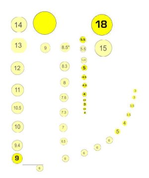
moulds.jpg


This was no fun to do. I do not wish to do it again. I keep copies of the group folder with all of the separate disk diameters on several HD.

I slide a disk until it just kisses the frame line inside.
I place all of the knowns.
I fill the in between with disk diameters to get a smooth curve . I usually replicate the big one almost all of the way and then a few that diminish/transition to the next known.

Once the deadflat mould shape group folder is complete, move a copy to the bottom of the line list - I call these tools "storage".
Move another copy of the group to the next frame in line. It is easier to just side a disk a little ways. Drop disks when things get crowded towards the bow and the stern.
I have near shoulder to shoulder disks from keel to rail, on a new layer I use the straight line drawing tool to connect the dots at the tangent point of every disk. (I use a 2 pixel line and the cursor circle at ~1 o-clock is a tangent)
Collapse the deadflat group to a single layer "Molds" - unless your program still plays nice when a file gets huge. Painter does not like it when file size exceeds its limit.
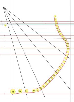
3_Renommee 8 .jpg

This is a series of line segments - of facets - and not a beautiful smooth curve. If the facets are short and all is close to being a curve I find it impossible to get anything but a smooth curve on the wood that it is the pattern for.


I recommend against replicating the blue diagram F1 to F1 design. I believe that the F1 to F1 cross chock over the keel a much more substantial. A heel to heel butt joint at the center of the keel was a weak point and was essentially forbidden. There were 3 choices that I have seen:
a half floor (a timber over the keel that is one half the length of the keel - I use for US 19thC. and French vessels)
a long arm F1 crossing the keel meeting a short arm F1 a ways away from the keel ( mid 19thC. merchant) whether it was PORT F1 long or STB F1 long was alternated along the keel.

A substantial cross chock. It was likely most often a mini half floor with the scarph to F1 a ways beyond the keel.

I have never seen it precisely defined but I take it that the "cutting down" was at the vertical line at the outside edge of the keel.

There was something else, but I lost the train of thought.
 
Last edited:
Yes, This is the moulded dimension. It is about as much actual data as there is,

I began using a drawing board - tee square - my father's high school drawing set - triangles. I did not like using a compass to draw circles with the moulded dimension radii then. In my drawing program I liked it even less. I intended to and have lofted frame timber pattern for a lot more than one ship. I found a different way that only had to be done once and is quick after the first ship.

I recommend: always loft at 1:48. It is easy enough to reduce the scale of the product.

Instead of circles with the radius, I use circles with the diameter.
I have a layer with a 1:48 ruler. It is transparent except for the hashs. I adjusted the scale until a printout of it matched my 1/4":1' architects triangle.
I found it! I found it! https://www.printmini.com/printables/rulers/1=48rule.pdf
The 10" - Import. Duplicate - magic wand select the background - not continuous setting - you want everything white gone - CUT.
It should be a transparent layer except for the actual ruler. It can be on top of another layer and the underlayer still be visible.
Once you have that save files of it in your lofting program's native format orrr PNG as the alpha layer.

On a new layer I used the lasso selector to form a circle over the ruler layer that is 12" in diameter. This was tricky because the lasso will be an oval if you let it.
Once it was a circle - I filled it with the brightest yellow I could conger up.
On a different layer I typed a black "12" with a font and point size that fit inside the yellow disk. I combined a copy of the yellow disk and the "12" on top into a single layer. I named the layer 12.
Two choices:
Use the lasso and do the work to get a perfect circle with every other diameter that might be needed.
Scale up or down a copy of the 12" disk. Each with its dia. ID.

Here is a copy of my moulds.rif file with all of the disk layers. I played with the lasso and a black background layer to get a black rim. More work but it helps old eyes - especially at the time before my cloudy cataracts were replaced.
View attachment 558537


This was no fun to do. I do not wish to do it again. I keep copies of the group folder with all of the separate disk diameters on several HD.

I slide a disk until it just kisses the frame line inside.
I place all of the knowns.
I fill the in between with disk diameters to get a smooth curve . I usually replicate the big one almost all of the way and then a few that diminish/transition to the next known.

Once the deadflat mould shape group folder is complete, move a copy to the bottom of the line list - I call these tools "storage".
Move another copy of the group to the next frame in line. It is easier to just side a disk a little ways. Drop disks when things get crowded towards the bow and the stern.
I have near shoulder to shoulder disks from keel to rail, on a new layer I use the straight line drawing tool to connect the dots at the tangent point of every disk. (I use a 2 pixel line and the cursor circle at ~1 o-clock is a tangent)
Collapse the deadflat group to a single layer "Molds" - unless your program still plays nice when a file gets huge. Painter does not like it when file size exceeds its limit.
View attachment 558579

This is a series of line segments - of facets - and not a beautiful smooth curve. If the facets are short and all is close to being a curve I find it impossible to get anything but a smooth curve on the wood that it is the pattern for.


I recommend against replicating the blue diagram F1 to F1 design. I believe that the F1 to F1 cross chock over the keel a much more substantial. A heel to heel butt joint at the center of the keel was a weak point and was essentially forbidden. There were 3 choices that I have seen:
a half floor (a timber over the keel that is one half the length of the keel - I use for US 19thC. and French vessels)
a long arm F1 crossing the keel meeting a short arm F1 a ways away from the keel ( mid 19thC. merchant) whether it was PORT F1 long or STB F1 long was alternated along the keel.

A substantial cross chock. It was likely most often a mini half floor with the scarph to F1 a ways beyond the keel.

I have never seen it precisely defined but I take it that the "cutting down" was at the vertical line at the outside edge of the keel.

There was something else, but I lost the train of thought.

Thank you Jaager,

Your's seems like a sophisticated method, and I won't claim to understand it in it's entirety. I'm working in small scales, so such high-precision may be lost in shaping and sanding. Not that I won't be working as precisely as I am able.

r.e. lofting - I'll create a 3D model of the hull. It is a bit involved, but using the plan I can then create a relatively smooth transition between station lines. Individual frames can then be cut from the model. Since there is a slight degree of linearity in my method, I'll design frames slightly oversized so that I can fair then to the correct shape during construction.

I'll see how the Goodwin dimensions for the interior walls match with the Staudt plans. If they are good enough, I'll lift the circles from the Staudt plan, or consider a compromise between the two. Using a Bezier function I can produce very accurate curves with very few points..Everything will be slightly oversized and faired anyway.

Because of the small scale, I though I'd get away with hide glue and butt joints, however, there was the predicted weakness. Now I plan to connect all timbers using a simple scarf joint as used on my 1:96 Enterprise kit. It works very well at 1:96 in boxwood. I gave up on the chocks. Way to fiddly.

futtocks5.jpg
 
Back
Top