• Win a Free Custom Engraved Brass Coin!!!
    As a way to introduce our brass coins to the community, we will raffle off a free coin during the month of August. Follow link ABOVE for instructions for entering.

PLANS

The term Mackinaw Boat indeed seems to apply to a variety of different small craft used on the Great Lakes. Chapelle discusses them along with sample drawings in his American Small Sailing Craft book. One of the more well documented variants goes by the name of “Collingwood Skiff.” Check out back issues in WoodenBoat magazine. They have had a number of articles.

Roger
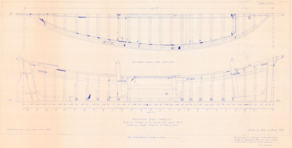
I experimented with the plans / table of offsets that Chapelle took off a half model of 'Mackinaw Boat - Lake Michigan type of about 1881'. But now I am heavily leaning toward using the plans of 'Wabesi':

1763095779406.png

I've also got table of offsets, body/ half breath / sheer / sail plans as redrawn by Roger Swanson. Rog
 
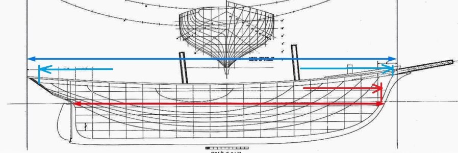
Length overall (loa): and Length on the waterline (lwl):

The 95ft 6 in is the LOA measurement and the red line is the LWL

Dictionary of American Naval Fighting Ships list the length of Naval ships at the LWL Admiralty drawings may record the length on deck or between perpendiculars. Then even between perpendiculars breaks down into overall and from the back of the stem to the front of the stern post. Then we have the add measurements which calculates the cargo capacity and cargo weight a ship can carry.
View attachment 555313
Could it be like this? Up to the tongue and groove (red). Up to the turntable (blue).

hull lines length.jpg
 
There are “Official” and unofficial lengths to describe the length of a ship or boat.

Official:

LBP- Length Between Perpendiculars. This is usually found on the Naval Architect’s lines drawing. Though not designated on the drawing above it would be approximately the same as the length of the Red Line above.

Load Waterline- As the name implies this is the length of the waterline at which the Naval Architect’s intended the vessel to float. In the case of a vessel like Gracie S. it would be measured with the vessel ready for sea; loaded with fuel and stores.

Commercial cargo carrying vessels are also governed by freeboard regulations. Freeboard is the vertical distance between the vessel’s weather deck and the water. This is marked at the waterline by the well known Plimsoll mark and differs depending on the situation; Summer, Winter, Fresh Water, etc. For these vessels, waterline length is measured at the summer load line.

Register Length- This is a legal measurement to establish Tonnage. Tonnage is supposed to be a measurement of the vessel internal volume that can carry cargo. It is NOT a measurement of Weight. It can be found in descriptions of vessels daring back to the 1500’s when one “Tun” was assumed to occupy 100 cu ft of cargo space. Like everything else in life its calculation has become musc more complex over time. The length used to measure it is similar to, but not necessarily the same as LBP. It has no application to ship model building EXCEPT researchers will find it used in Ship Registers (like Lloyds) and Customs House descriptions.

Unofficial:

Length Overall- Usually the longer blue line shown in Kurt’s post above but depends on the situation. Selling a boat, advertise it to be as long as possible, Haggling with the marina or harbor master over docking fees, keep it short.

Roger
 
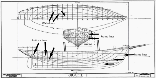
More basic terms to know
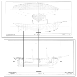
You point out frame lines, but I wonder, are they frame lines or station lines? They line up in the forward frame of each pair, but not in the exact same place for each pair. If they were frame lines wouldn't it be better if they lined up in the middle of the pair or perhaps the leading edge or after edge? The center to center distance of the double frames is 25.44" but the center to center of the body plan lines is 26.05" Then again, perhaps, one or both of the drawings are not correct. I enlarged these to full scale, but if the 1:48 drawings are not accurate, enlarging them is not meaningful. At 1:48 it is not a huge thing, but something is amiss, be it the drawings are not accurate or they are, but there is no relationship between the station lines and the location of the frames.
Allan

1763234090457.png
 
Yes, they are probably station lines. In preparing a lines drawing, the Naval architect spaces station lines to best describe the shape of the hull. As this lines drawing would be redrawn full size by the mould loft, orientation of the frames could be determined then. The table of offsets sent to the mould loft would include a note specifying frame spacing to meet the Naval Architect’s structural requirements.

I realize that there were conventions in places like Royal Navy dock yards where lines drawing stations represented some fixed multiple of frame spacing.

Roger
 
Then again, perhaps, one or both of the drawings are not correct.
For shaping my solid hull I am relying primarily on Sheet 1, and using the Inboard Profile as secondary. For interior aspects, I'm making use of the Interior Profile and the Beam Plan.
 
Here is an abridged version of the lofting from my proposed log:
Painter would not open the TIFF. I went to PS in the cloud and cropped the lines sheet into three sections and saved them as PNG (lossless format)
I did the same for section 14 and inboard profile.

OPEN Profile.png
it is Huge! enlarge canvas if necessary
Adjust orientation - compare a station to base - duplicate layer - ROTATE - trial -fail - delete layer - duplicate new - test repeat until the orientation is correct
Check plan scale to 1:48 ruler 10' = 19.25' - duplicate layer - SCALE with estimated values - turns out that 51.9% produces 10'=10'
Add a legend layer identifying each station with its number

OPEN Body.png
SCALE a duplicate adjust 51.9%
ROTATE to match baseline
CUT background
Body delineates the station numbering.

The profile has no information about the decks.

OPEN inboard profile.png
ROTATE to match baseline - check scale SCALE to 1:48 - CUT background - overlay profile 48
I am guessing that the deck locations are at the keel/midline.
In section 0 the cockpit deck is horizontal.
In section 14 the cabin deck is horizontal -
the deck has a roundup

OPEN roundup.png (section 14) ROTATE to match baseline - check scale SCALE to 1:48 - CUT background
Measure the roundup of the deck beam = 3.5"
Move deck layer1 down 3.5"

Reading this - something comes to me:
My station/frame patterns have the location of the rail, LWL, rabbet, and top of deck beam at side. (GracieS has no gunports so no sill or lentel. No wales either.)
By dropping the deck 3.5" along its whole length I have made each beam have the same crown height. I am going to have to figure a fudge factor to get the height of beam at side going higher as it progresses to the bow and stern.


This is a long way of saying that each TIFF was a different scale and had its own rotation. Since Profile, Body, WL are all on the same sheet, the rotation and scale are the same. All of the stations have the same interval. I use them as being the midline of every other bend. I found no strangeness with the plans.
 
Last edited:
You point out frame lines, but I wonder, are they frame lines or station lines? They line up in the forward frame of each pair, but not in the exact same place for each pair. If they were frame lines wouldn't it be better if they lined up in the middle of the pair or perhaps the leading edge or after edge? The center to center distance of the double frames is 25.44" but the center to center of the body plan lines is 26.05" Then again, perhaps, one or both of the drawings are not correct. I enlarged these to full scale, but if the 1:48 drawings are not accurate, enlarging them is not meaningful. At 1:48 it is not a huge thing, but something is amiss, be it the drawings are not accurate or they are, but there is no relationship between the station lines and the location of the frames.
Allan

View attachment 557225
Yup. Station lines. I guess frame lines would be, naturally, on the frames.
 
Yup. Station lines. I guess frame lines would be, naturally, on the frames.
Hi Kurt.
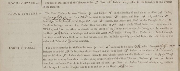
Many, not all, plans have the edge of a frame right on the station line. With the siding of the floors and lower futtocks being different fore and aft of the midships area in some cases, the space between the floors and lower futtocks changes as well in order to maintain the same room and space. Diana (38) 1794 is a great example of how the siding changes but not the room and space, plus the station lines do fall on the center of the sistered pair of frames on the original plans. It can be very confusing at times as nothing remained the same over time or nation.
Allan
1763289196789.jpeg
1763289310571.png
 
Hi Kurt.
Many, not all, plans have the edge of a frame right on the station line. With the siding of the floors and lower futtocks being different fore and aft of the midships area in some cases, the space between the floors and lower futtocks changes as well in order to maintain the same room and space. Diana (38) 1794 is a great example of how the siding changes but not the room and space, plus the station lines do fall on the center of the sistered pair of frames on the original plans. It can be very confusing at times as nothing remained the same over time or nation.
Allan
View attachment 557364
View attachment 557365
Thanks for the detailed explanation. In all things, there are more exceptions than rules! :D
 
While it is natural to relate their use to well documented British Government (Royal Navy) shipbuilding practices not all ships were built from formal lines drawings.

While British trained shipwrights working in American shipyards could and did draw formal lines drawings, many American built vessels were built from half models. For example, there are no lines drawings known to have been drawn by the famous Nathaniel Herreshoff who worked into the 1920’s. His designs all began with half models. They still exist at the Herreshoff Museum in Bristol, RI. Based on my review of technical papers, half models were also used here on the Great Lakes into the very late 1800’s. There is also a half model of a steel hulled Great Lakes bulk carrier that has been segmented for tracing body plan sections displayed in a museum in Duluth, MN And finally, in his descriptions of models built for the Smithsonian’s Collection, Howard Chapelle often writes that lines were taken from half models.

On the other hand lines drawings do exist for many but not all of the packets and clippers built in America during the Mid-Nineteenth Century. William H. Webb published them in a Portfolio and John Griffith’s published some in his magazine. This does not mean that these are actual design documents. Author William Crothers writes, that the half model was still the preferred method for designing these beautiful vessels. He lists 11 such half models in the Smithsonian’s collection. This includes the one for the Webb built Clipper Challenge. A lines drawing for Challenge is also included in Webb’s Portfolio of drawings but a note on the drawing implies that it was produced when she was drydocked for coppering in England.

Roger
 
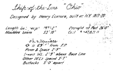
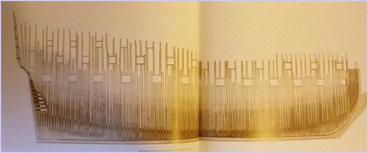
At the Naval Yard the station lines were on the frames case in point the OHIO the red lines are the station lines the blue lines are 3 frames between each station line. bow and stern the red station lines are every other frame

OHIO.jpg

We know this because it says it on the plans frames center to center are 2 feet 9 inches

OHIO close1.jpg

Maybe this is how Henry Eckford drew plans or if it was standard at naval yards to space the stations on frames Or maybe there was no actual standard and each master shipwright did things his way.
 
The Royal Navy cast a long shadow on the building of USNavy sailing ships. This does NOT mean that the Americans copied British designs. Far from it, the very large vessels within each class was an American innovation. But several American shipbuilders had been trained in British dockyards learning British drawing conventions.

In American yards not operated by the navy, as I explained in a previous post, the use of half models by less formally trained shipwrights eliminated the need to make formal lines drawings so laying out frames could be delegated to the mould loft.

Roger
 
Frame is a confusing and not at all clear name unless the definition is restricted.

I define frame as being a single series of timbers. All of the timbers lay in the same cross sectional plane.
A bend is a joined pair of frames. The timber butts of one frame are supported by the middle of a timber in the partner frame.

If "frame" is used to mean either a single unit or the paired unit -additional words must be typed when what is being described is the pair. Bend is quicker.

In my experience, the RN: a station defined and was the location of the midline of a bend. The exception was if the framing was all frames. In this situation the floor timber is on the aft side of its station AFT and fore side FORE. Special arrangements occurred at the deadflat.

As long as there has been wooden ships - there has been a fight with fungal rot. The frame timbers need to lose the water within its entire matrix from its living state before a fungus migrating in from its surface can utilize the internal water to eat the wood. A first rate with 15" thick floor timbers may need 15 years to totally season. The RN did not have the science, but they knew that for frame timbers not to quickly rot - there needed to be good air circulation. Two of the four faces are blocked by planking, If a bend had the timbers of one frame flush against the face of its partner - each timber was down to one face. Fungus always wins if 75% of evaporating surface is occluded? If 1" or 2" spacer chocks are used between every frame - bend and single filler frame the surface area is double. Often on design plans the station line is drawn in the gap with the spacer chocks. That does not mean that frames on either side are not a bend. A bend was probably a single unit while it was horizontal. The bolts going thru both frames and the chock between them secured tightly at both ends. The next up frame would have bolts with a blind end into the already standing frame. The design plan may have a style to reflect the difference. Air flow was a big deal. To me, it looks as though the designer was trying to idiot proof the plans to keep the yards from saving time and money by skipping the chock part and going quick and dirty.
As a modeler -I do go quick and dirty. My timbers are already seasoned and they will stay dry. There are no more young gentlemen seeking to learn the craft. I see no need to frame my models as though they are intended to be used in classroom instruction. I will repeat my conviction: compared to actual practice, any framing done in a model is of necessity "stylized". The reality would have been irregular and ugly and unworthy of display. As long as it is already stylized - why not pick an elegant and artful style? Why go complex and dense when it is not actually real? The regularity of a design plan was a wish. It was the ideal version of the ship.

As a general rule, I believe that the French and the North Americans built using all bends. There had to have been exceptions. Neither had the timber availability problems that the English faced. Both desired minimum cost and maximum efficiency from their shipyard workers. Well, I am guessing that the French played this. How I see it: The English needed jobs - make work - out of control union style where seniority supersedes skill - labor intensive complexity was a plus.
 
Last edited:
the use of half models by less formally trained shipwrights eliminated the need to make formal lines drawings so laying out frames could be delegated to the mould loft.
Everything that I have read indicates that only the station shapes were on the mould loft floor. The timber patterns were just for the stations. Probably on the floor as well as the patterns "surmarks" were used to define the intervening frame shapes.
A half model would not have had to be sliced into all that many pieces.
 
The reality would have been irregular and ugly and unworthy of display.

I'd absolutely love to make frames like this. I wish I knew how?

Though the regular frames are practical, they can lack character in some cases. I think slightly irregular frames would be very beautiful and elegant.

As I am very new to ship modelling, please correct me if I've got the wrong end of the stick but the closest that I've seen is Richard Ensor's 'The Restoration Warship'. I've explored trying to create a similar effect, but do not really know how. I would love advice on it.

In the last sentence of the plate description below Ensor says, "The spacing of the frames was not co-ordinated with the spacing of the gunports so that individual arrangements were made for each one as they were cut out". When Ensor writes ''Each one'', is he referring to the gunports or the frames?...................................


20251119_061752.jpg

20251119_062802.jpg
 
Back
Top