...I have never tried to fail, I always trying to succeedif you try to fail and you succeed then which one have you done?
-

Win a Free Custom Engraved Brass Coin!!!
As a way to introduce our brass coins to the community, we will raffle off a free coin during the month of August. Follow link ABOVE for instructions for entering.
-

PRE-ORDER SHIPS IN SCALE TODAY!
The beloved Ships in Scale Magazine is back and charting a new course for 2026!
Discover new skills, new techniques, and new inspirations in every issue.
NOTE THAT OUR FIRST ISSUE WILL BE JAN/FEB 2026
You are using an out of date browser. It may not display this or other websites correctly.
You should upgrade or use an alternative browser.
You should upgrade or use an alternative browser.
Princess Charlotte 1814
- Thread starter Dave Stevens (Lumberyard)
- Start date
- Watchers 8
-
- Tags
- 1814 princess charlotte
better trying to "surwive" - I spell it "surwife"...I have never tried to fail, I always trying to succeed
Good work on the stern structure - everytime good to learn something new
- Joined
- Dec 1, 2016
- Messages
- 6,383
- Points
- 728

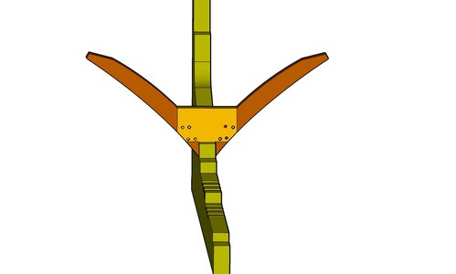
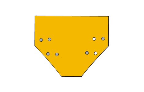
working from a description of what these chocks in the stern timbers looked like i came up with this 3D model
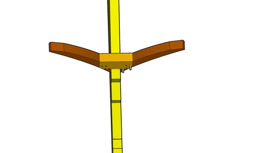
from the front it looks like this it has 4 holes for iron rods.
note: there were no wood treenails use in the construction of the Princess Charlotte it was all iron rods and spikes
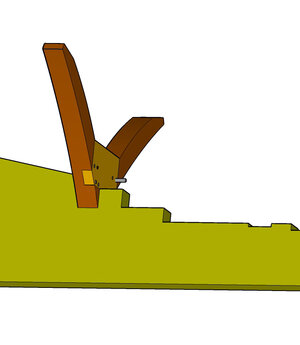
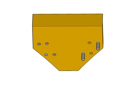
tilting the chock a little forward you can see the thickness and the iron rods
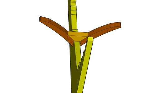
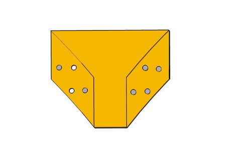
looking at the back view
and an isometric view of the back where it fits into the notches of the floor timbers
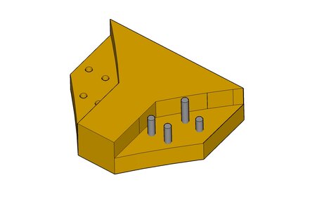
once again some pretty fancy joinery
vertical building of a model is as intense and time consuming as building a model in reality.
now i need to take this chock and add it to the floors so we can see how it fits.
each and every frame has 3 chocks one cross chock that cross the keel and joins the floors and 2 chocks that join the head of the floors to the second futtock.
Each and every chock is made to fit its intended location so no one chock can be used anywhere else.
aside from the 3D modeling 2D CAD drawing are made for every part. top, side, bottom and back view.
actually all the parts can be CNC milled and the model assembled as a 3D puzzle OR challenge your skills and do all the joinery by hand,
from the front it looks like this it has 4 holes for iron rods.
note: there were no wood treenails use in the construction of the Princess Charlotte it was all iron rods and spikes

tilting the chock a little forward you can see the thickness and the iron rods

looking at the back view

and an isometric view of the back where it fits into the notches of the floor timbers

once again some pretty fancy joinery
vertical building of a model is as intense and time consuming as building a model in reality.
now i need to take this chock and add it to the floors so we can see how it fits.
each and every frame has 3 chocks one cross chock that cross the keel and joins the floors and 2 chocks that join the head of the floors to the second futtock.
Each and every chock is made to fit its intended location so no one chock can be used anywhere else.
aside from the 3D modeling 2D CAD drawing are made for every part. top, side, bottom and back view.
actually all the parts can be CNC milled and the model assembled as a 3D puzzle OR challenge your skills and do all the joinery by hand,
- Joined
- Dec 1, 2016
- Messages
- 6,383
- Points
- 728

i personally do not intend on building a stern section of the Princess Charlotte, this is just an exercise in 3D modeling and CAD design for fun. But it crossed my mind to create STL print files and print all the parts in clear resin and assemble a model, maybe in my retirement, ya right!
- Joined
- Dec 1, 2016
- Messages
- 6,383
- Points
- 728

- Joined
- Dec 1, 2016
- Messages
- 6,383
- Points
- 728

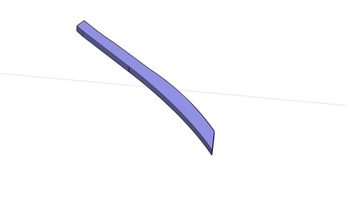
next is the first futtock which is a simple timber no joinery on this piece
the heel of the timber sits against the side of the rising wood and it is bolted to the floor and to the rising wood.
it goes behind the floor timbers
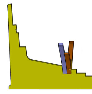
view of the back
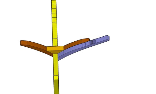
view of the front
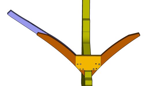
and a view looking down
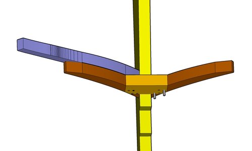
setting in the other side futtock front view
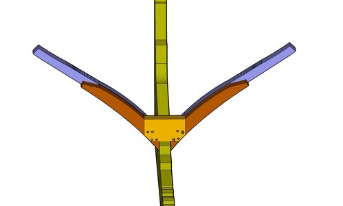
back view
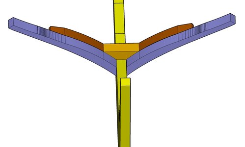
sde view
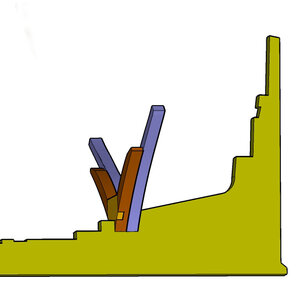
the heel of the timber sits against the side of the rising wood and it is bolted to the floor and to the rising wood.

it goes behind the floor timbers

view of the back

view of the front

and a view looking down

setting in the other side futtock front view

back view

sde view

Last edited:
- Joined
- Dec 1, 2016
- Messages
- 6,383
- Points
- 728

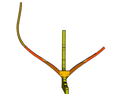
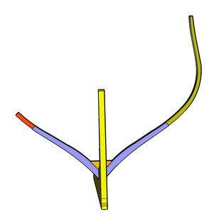
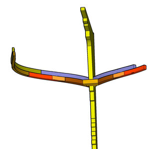
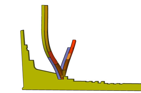
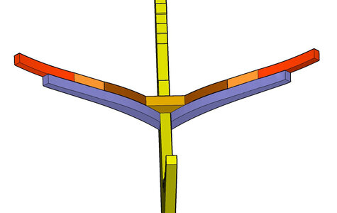
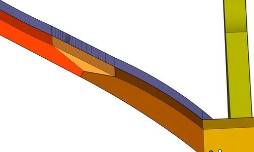
chocks were used to connect the second futtock to the head of the floor.
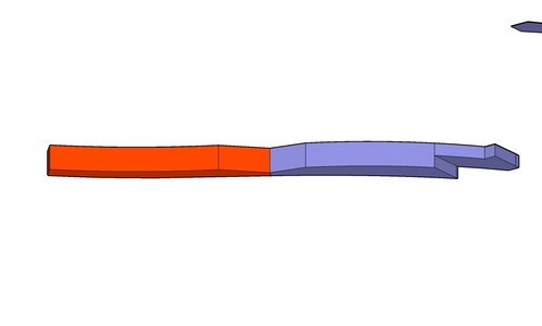
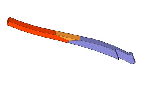
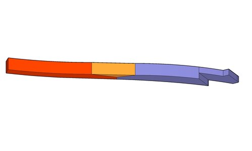
building up the frame timber by timber
view facing the stern forward face of the frame

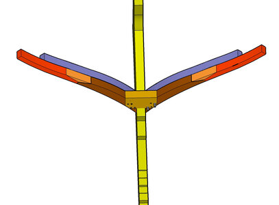
view facing the stem back side of the frame
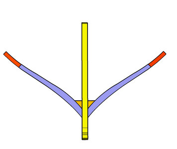
there is a void behind the cross chock and between the 1st futtocks that will be filled in with deadwood pieces.


building up the frame timber by timber
view facing the stern forward face of the frame


view facing the stem back side of the frame

there is a void behind the cross chock and between the 1st futtocks that will be filled in with deadwood pieces.


- Joined
- Dec 1, 2016
- Messages
- 6,383
- Points
- 728

- Joined
- Dec 1, 2016
- Messages
- 6,383
- Points
- 728

i am not going to complete the rising wood frame because i have in mind to leave frames incomplete in various stages to show their construction, so now moving to a frame that sits on the keel. This is how all the frame that sit on the keel are built.
the keel has a rising wood on top and it is notched for the floor timbers
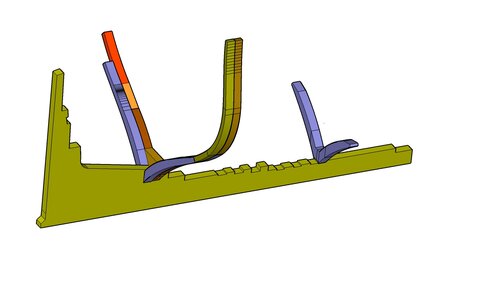
the first futtocks on the stern rising wood sit against the side and bolted into the rising wood, on the keel the first futtocks are notched "over" the rising wood and butt to one another at the center. There is nothing attaching these timbers to the keel they are bolted to the floors and the floors are bolted to the cross chock and the cross chock has a bolt that runs through the keelson through the chock and into the keel.
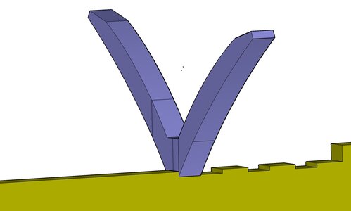
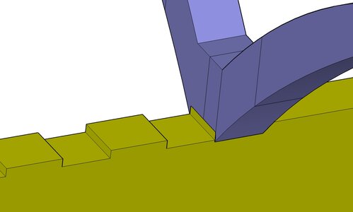
the keel has a rising wood on top and it is notched for the floor timbers

the first futtocks on the stern rising wood sit against the side and bolted into the rising wood, on the keel the first futtocks are notched "over" the rising wood and butt to one another at the center. There is nothing attaching these timbers to the keel they are bolted to the floors and the floors are bolted to the cross chock and the cross chock has a bolt that runs through the keelson through the chock and into the keel.


Last edited:
- Joined
- Dec 1, 2016
- Messages
- 6,383
- Points
- 728

There were two archaeological field studies maybe more but i have two, done on the wreck over a few years and i found differences in the discription on how these keel frames were built. To reconstruct the model first i have to imagine it in my head, do a 2D CAD drawing and convert the 2D into 3D.
So i got to think about it and try different ways to see what will work and what won't.
The made floors were constructed by attaching two frame timbers to either side of a
cross-chock using three bolts per side. The cross-chock and its associated
frame timbers fit together with vertical scarfs that extend from the keel centerline to the
outer ends of the cross-chock. A 1-inch diameter bolt driven through the
keelson, cross-chock, and into the keel fastened each made frame assembly into place.
The individual cross-chocks, while maintaining the same basic form, differ in their
dimensions. Each cross-chock fit its corresponding frame timbers very tightly. This
means that rather than cutting chocks and notches to pre-determined shapes they were all
custom cut and formed as individual units and fitted together as such. No chock could
be used with a different set of timbers than the ones it had been cut for. The heels of the
first futtocks were notched to fit over the keel, and a simple triangular unfastened chock
was placed atop the futtock heels to fill in the space between the frame and keelson.
In many cases the made floors were not notched over the keel, but instead the top
surface of the keel was notched to fit the floors.
well ok imagine it and 3D model it
Last edited:
- Joined
- Dec 1, 2016
- Messages
- 6,383
- Points
- 728

the made floors were not notched over the keel, but instead the top surface of the keel was notched to fit the floors.
the statement above is what has me puzzled
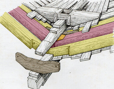
here is a drawing of the timbers from another survey of the wreck
we see the cross chock up front behind it are the 2 floor timbers with the vertical scarf for the cross chock what i see is the floors are drawn notched over the keel and no notch in the rising wood.
behind the floors in red are the first futtocks with the chock sitting on top. The first futtocks are sitting against the cross chock and the floors behind it.
so the cross chock is higher in the center above the top of the floors thus the need for the chock on top of the 1st futtocks.
i can see as each frame changes shape the cross chock has to change.
keeping in mind the historical drawings were "as built" that means the Princess Charlotte was built without any drawings. The drawings were done after the ship was built and not before. All i can say is "holy smokes" those ship carpenters were good!

- Joined
- Dec 1, 2016
- Messages
- 6,383
- Points
- 728

oh good grief! i totally messed up sheesh
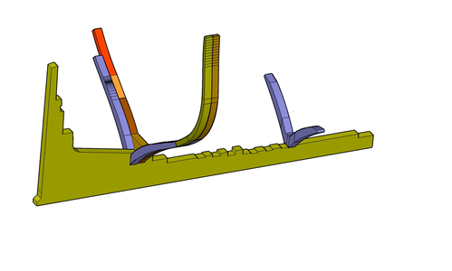
see that frame to the right those are floor timbers wrong timber in the wrong place. those timbers should set in the notch and not notched over the keel i think?
it should look like this no angle for a chock at the head of the timber and a longer timber to go past the chock
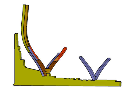

see that frame to the right those are floor timbers wrong timber in the wrong place. those timbers should set in the notch and not notched over the keel i think?
it should look like this no angle for a chock at the head of the timber and a longer timber to go past the chock

- Joined
- Dec 1, 2016
- Messages
- 6,383
- Points
- 728

In many cases the made floors were not notched over the keel, but instead the top
surface of the keel was notched to fit the floors.
i wonder if the frames were built both ways with and without notches in the floors it does say "in many cases" dazed and confused
surface of the keel was notched to fit the floors.
i wonder if the frames were built both ways with and without notches in the floors it does say "in many cases" dazed and confused
- Joined
- Aug 10, 2017
- Messages
- 1,706
- Points
- 538

Hi Dave, in your last post for the PC you said the drawings were “as built” that means the Princess Charlotte was built without drawings. That in not exactly correct. As built means after the ship was built any deviations from the construction drawings was noted and the drawings were revised to the actual construction. The carpenters were good, but they didn’t design the ship.the made floors were not notched over the keel, but instead the top surface of the keel was notched to fit the floors.
the statement above is what has me puzzled
here is a drawing of the timbers from another survey of the wreck
we see the cross chock up front behind it are the 2 floor timbers with the vertical scarf for the cross chock what i see is the floors are drawn notched over the keel and no notch in the rising wood.
behind the floors in red are the first futtocks with the chock sitting on top. The first futtocks are sitting against the cross chock and the floors behind it.
so the cross chock is higher in the center above the top of the floors thus the need for the chock on top of the 1st futtocks.
i can see as each frame changes shape the cross chock has to change.
keeping in mind the historical drawings were "as built" that means the Princess Charlotte was built without any drawings. The drawings were done after the ship was built and not before. All i can say is "holy smokes" those ship carpenters were good!
View attachment 343897
- Joined
- Dec 1, 2016
- Messages
- 6,383
- Points
- 728

good point Mike some place in the Canadian archives are letter to and from the Kingston naval yard that might shed light on the subject.
i will do a little archive digging and see if i can find out anything
i will do a little archive digging and see if i can find out anything
- Joined
- Dec 1, 2016
- Messages
- 6,383
- Points
- 728

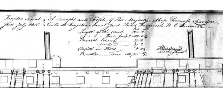
the Princess Charlotte was started sometime in the fall of 1813 and launched Christmas day 1814 the plans are dated July 1815 almost 2 years after the ship was being built.
Like you said Mike "as built" may be changes made from the original plans. We do have the plans of the second frigate Psyche on those plans you clearly see the changes were noted and redrawn over the existing plans. In the case of the Psyche "as built" no doublt about it we have the original drawing and the over drawing on the same plan showing the as built.
With the Princess Charlotte we have one drawing that shows no changes to an original. In this case the one drawing in 1815 is the original there was no drawing before July 1815. Or was there? i don't know.
there are no existing plans of the ships built on the lakes by Eckford and Brown or by Willian Bell so it might be possible these guys built these ship with no drawings. That boggles my mind how they did it.

Interesting research and designchocks were used to connect the second futtock to the head of the floor.
View attachment 343671View attachment 343672View attachment 343673
building up the frame timber by timber
view facing the stern forward face of the frame
View attachment 343666
View attachment 343669
view facing the stem back side of the frame
View attachment 343667
there is a void behind the cross chock and between the 1st futtocks that will be filled in with deadwood pieces.
View attachment 343668
View attachment 343670
would the chocks not have such a form?
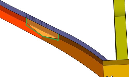
With the pure triangle the sliding and shear forces would be much higher
- Joined
- Dec 1, 2016
- Messages
- 6,383
- Points
- 728

Interesting research and design
would the chocks not have such a form?
i noticed the same thing chocks looked like the way you drew it with the ends cut square. That is the excepted shape and accepted by model builders as historically correct, but with the Princess Charlotte construction methods show there were no "standard" shapes, ways or how things were done. Much depended on the master shipwright and the carpenters. This is what makes the Princess Charlotte, Prince Regient, Psyche and the St. Lawrence so interesting they show us there were no typical or standard construction methods every ship built was a one of a kind.
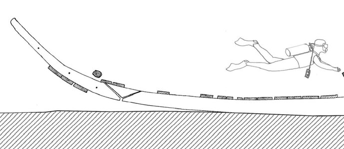
I used the shape based on archaeological field drawings of the wreck, there are entire photo projects done of the wreck but so far i have not been able to search these archives, i have not come across an actual image of a chock on the wreck. Even if the ones drawn do not necessarily mean all the chocks were cut the same.


- Joined
- Dec 1, 2016
- Messages
- 6,383
- Points
- 728

back to the floors of the frames that sit on the keel
the floors sit in the notch
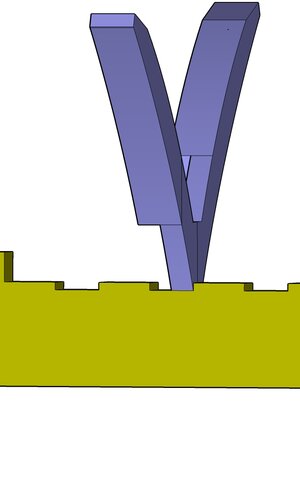
the bottom of the floor timbers are flat there is no notch cut into them
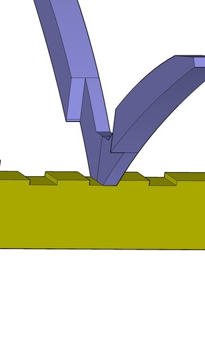
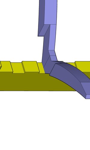
the other part of the keel notch is where the cross chock will sit. We are facing the stern so the chock is in front of the floors.
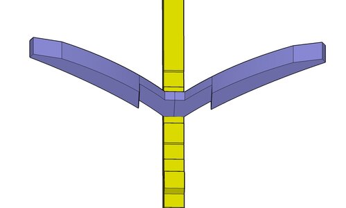
now for the cross chock. it is bolted to the floors with 3 iron rods per floor and a iron bolt ran through the keelson all the way through the chock and into the keel.
note: the term "bolt" is used in the construction but bolt is not what we think of as a modern day bolt with a threaded nut at one end. Back then a bolt is an iron rod with a clench ring at the end.
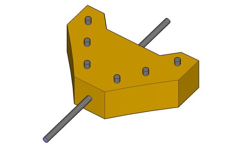
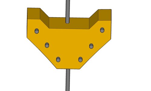
the cross chocks along the keel were different than the ones used on the stern rising wood, the keel cross chocks were flat front and back and not like the stern frame chocks
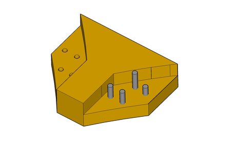
the floors sit in the notch

the bottom of the floor timbers are flat there is no notch cut into them


the other part of the keel notch is where the cross chock will sit. We are facing the stern so the chock is in front of the floors.

now for the cross chock. it is bolted to the floors with 3 iron rods per floor and a iron bolt ran through the keelson all the way through the chock and into the keel.
note: the term "bolt" is used in the construction but bolt is not what we think of as a modern day bolt with a threaded nut at one end. Back then a bolt is an iron rod with a clench ring at the end.


the cross chocks along the keel were different than the ones used on the stern rising wood, the keel cross chocks were flat front and back and not like the stern frame chocks

- Joined
- Dec 1, 2016
- Messages
- 6,383
- Points
- 728

i don't know if this is true or not but i wondered why frames were built with one 1/2 sitting in a keel notch and the other half (1st futtocks) notched over the keel, exactly how the Princess was framed. I saw this on several other wrecks.
the answer i got was if the floor or in the case of the Princess the chock/floor sat flat on the keel the rod that ran through the keelson, floor and into the keel the rod would act as a pivit point and you could spin the floor timber around the rod. but if the floor and a tight fitting cross chock sat in a notch that locks the timbers from moving in a fore and aft direction. with the first futtock notched over the keel prevents movement from side to side. So a frame is locked in side to side and front to back.
structures of a ship is not ridgid it is dynamic and everything wants to move making the joinery an important part of the structure.
true or not it does make sense

