- Joined
- Dec 1, 2016
- Messages
- 6,383
- Points
- 728

another pieces of information that might be true or might not
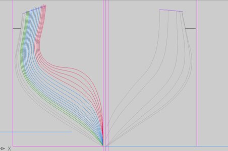
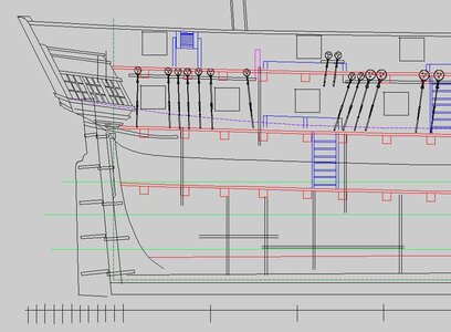
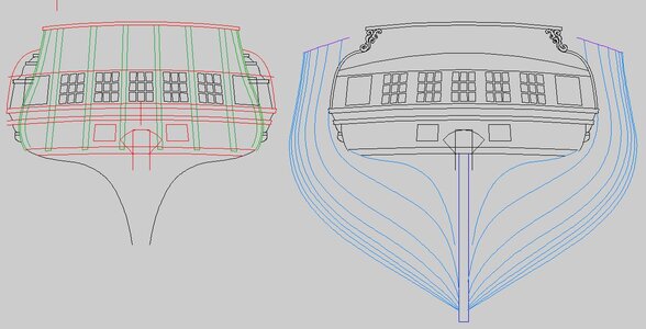
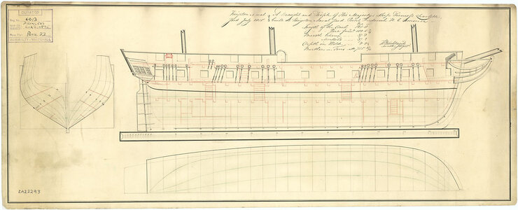
these super frigates built on the lakes were a wakeup call for British shipwrights and that is why they are built so different from the typical British ships.
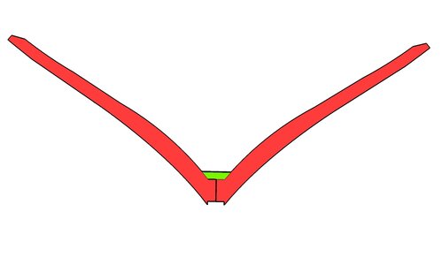
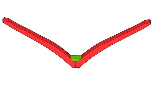
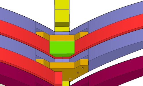
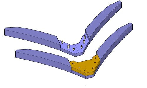
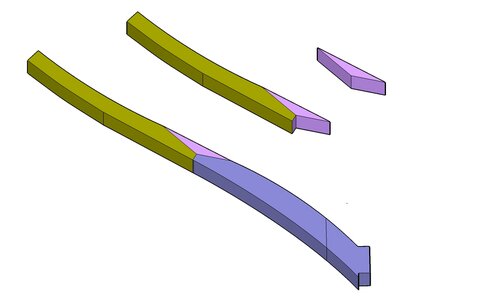
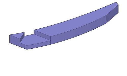
The British built ships with sistered frame every other or every third frame then filled in between these frames with loose filler timbers.
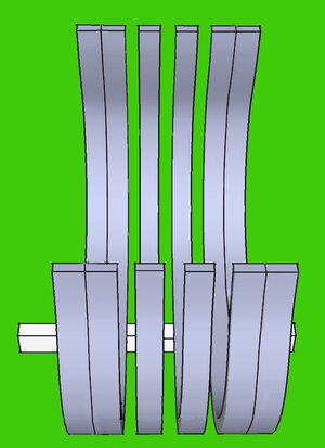
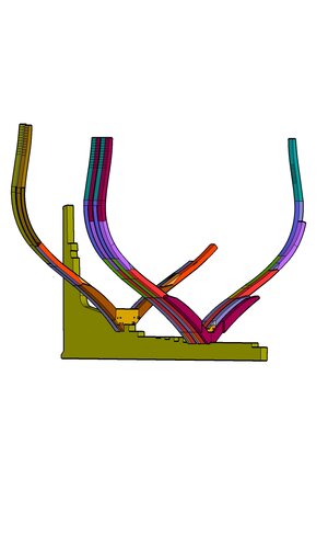
they even went as far as to reduce the size of the frame pieces as the frame reached the top which is another British thing American built ships did not tapper, same size from the keel to the cap rail.
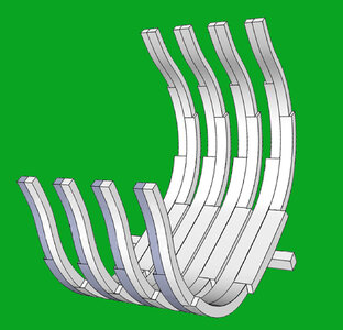
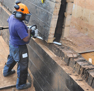
my guess was to reduce weight, less weight the faster the ship. This worked until the British faced the American frigates and their cannon shot bounced off the sides of the ships. Thus the nick name "old iron sides" while the Americans could do a lot of damage to the British ships. American built war ships were a solid wall of heavy timber as you can see during repairs of the Constitution
The British admiralty realized their hull construction was no match for the American build hulls so they took the American system and used it in the construction of the super frigated built on the lakes.
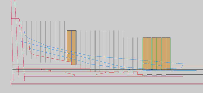
this double frame filler frame style for some odd reason was thought that is how all ships must of been built as we can see in a model of the American Built confederacy model. Wrong style of framing for an American built ship. Like the Princess Charlotte the Confederacy would have been almost a solid wall of sistered frame very close together.
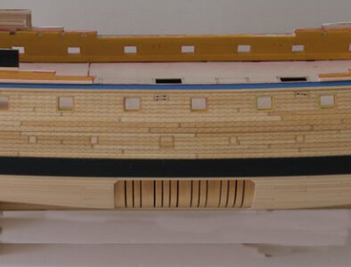
this all begs the question how picky can you get when it come to actual historical accuracy and does it really matter?
in the academic world very picky down to the smallest detail, in the hobby of model ship building not so much. Could be why the "hobby" is not taken all that serious by the academic community there is a lot of artistic license going on in the hobby, which is well and fine.
these super frigates built on the lakes were a wakeup call for British shipwrights and that is why they are built so different from the typical British ships.
The British built ships with sistered frame every other or every third frame then filled in between these frames with loose filler timbers.

they even went as far as to reduce the size of the frame pieces as the frame reached the top which is another British thing American built ships did not tapper, same size from the keel to the cap rail.

my guess was to reduce weight, less weight the faster the ship. This worked until the British faced the American frigates and their cannon shot bounced off the sides of the ships. Thus the nick name "old iron sides" while the Americans could do a lot of damage to the British ships. American built war ships were a solid wall of heavy timber as you can see during repairs of the Constitution

The British admiralty realized their hull construction was no match for the American build hulls so they took the American system and used it in the construction of the super frigated built on the lakes.
this double frame filler frame style for some odd reason was thought that is how all ships must of been built as we can see in a model of the American Built confederacy model. Wrong style of framing for an American built ship. Like the Princess Charlotte the Confederacy would have been almost a solid wall of sistered frame very close together.

this all begs the question how picky can you get when it come to actual historical accuracy and does it really matter?
in the academic world very picky down to the smallest detail, in the hobby of model ship building not so much. Could be why the "hobby" is not taken all that serious by the academic community there is a lot of artistic license going on in the hobby, which is well and fine.


