Privateer Viper 1/24th Scale

Now is the time to complain about how people draw on their program and explain why I am right and most everyone else is wrong.

First in 3D you have 3 planes you can draw on. A front plane, a top plane and a right plane.

this is usually standard along all 3D programs.

I draw my profile view on the front plane, waterlines on the top plane, and stations or frames on the right plane.

Most people switch and draw the stations on the front plane and the hull profile on the right plane. in essence this doesn't really affect your drawings that much.

If you think about it the front view of a ship is actually looking down through the stations from front to back.

However that is not how cad programs are set up. the names of the drawing planes are just that just names it isn't supposed to mean front of object or right of object or even top of object as top view could very well be bottom view.

What is affected by drawing it this way is how your ship is displayed.

I like to view my ship in isometric trimetric and dimetric views to see it from varying angles for errors and you usually want to look down the ship from front to rear. If you draw like most guys you wont get those views you will get basically an angled side view.

the reason is most cad programs do their perspective and iso views from right to left. and if your right view is the side of the ship you dont get the proper views. thus ALWAYS use the front drawing plane as your profile view and the right drawing plane as your station or front back view.
 
So the next step after getting your dimensions is to create sketch planes for your frames. here is where it can be tricky. IF your software has a global origin point then everything will be fine as everything is lined up to that. IF your software doesn't then you need to figure out where it creates its planes from. usually there is an option to turn on planes and you can see where the 3 planes are located and intersect. you then have to move everything to that intersection point.

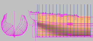
So Now using the Right plane you want to create a new right plane for each station. in this case the aft stations and you use your measurements to tell the program where to place the planes. you can see how I did it in the image below. they are the dark blue lines

24 Scale Privateer -23.png
 
Next we need to look at our bodyplan. We want to draw a line from the top of the keel to our bodyplan (which you should already have in proper location) and chop off the centerline of the bodyplan to that line. where the centerline meets the keel top we need to line all our stations to that point when we place the drawings on the new planes we created.

There are a couple ways we can do this. we can create another right plane behind our profile view, we then copy our bodyplan onto that and line it up properly. we then just have to trace each station on the appropriate plane we created for our stations

24 Scale Privateer -25.png24 Scale Privateer -26.png
 
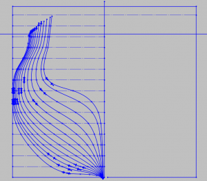
Now I want to show that when I trace my bodyplane I draw the waterlines across it and use splines to draw my body plan. I also run waterlines equally spaced all the way past the tops of the stations.

when I trace my stations I place a node everywhere there is a waterline. this will smooth the curves quite a bit and also when Lofting you get a much better loft if each station has the exact same number of nodes. I still have to add a few to the bottom later on but just did a quicky for now

24 Scale Privateer -30.png
 
then after I get my stations I play connect the dots with a 3D spline to give me waterlines which I can then check for fareness. Once I am happy I delete most of the waterlines leaving a few in place in key areas. the reason is that sometimes too many water lines can make for rough sharp cornered sides on your loft. only experimentation can tell you when enough is enough. you may have to add or delete waterlines in certain areas to get the perfect loft as it is all trial and error.

that then takes us to where I am at now. for the bow section you just repeat what you did in the aft section

24 Scale Privateer -28.png24 Scale Privateer -29.png
 
How can I ever repay you Joseph for all of this information.
A million thanks wouldn't be good enough.
Bravo mate
Greg
 
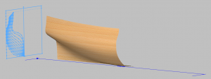
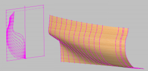
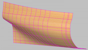
and here I am lofting up the hull. I had to leave the first couple off as it was messing up the loft. However there is a small fix that will help and that is to fill in the missing stations which will help the loft hold shape better as it nears the front. that is why I can skip a bunch until I get a nice smooth loft like this is doing.

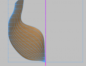
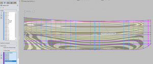
As you can see all the nice straight flowing lines along the hull. Solidworks shows the loft as zebra stripes as you loft to find areas that ar ebad. the funny looking areas in the aft and bow are expected as that is where the hull dips back in.

So I will finish the loft and then add all the missing stations up to the end of the bow loft then it is a matter of trial and error short lofts in order to get the smooth flow we need.

90% of lofting is just trial and error adding or deleteing stations to the loft until it flows smooth.

24 Scale Privateer -34.png
 
What does lofting mean?
Greg


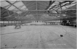
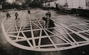
it is a term used in ship building where draftsmen create patterns in full scale from a set of drawings. This was done on the floor of a loft usually above the shop

wpe10.jpg

you can see the draftsmen and the plans to the right from these plans full size molds or patterns were made and sent out in the yard where the foreman would select the wood to fit the part.

mold-loft1.jpg
 
Thanks Dave for that explanation. I have learnt something today, so today is not waisted.
My grandfather had a saying, 'if you learnt something today, today wasn't a waisted day'!
Happy3dmodelling
Greg
 
no didit Lofting is also a term in CAD and what lofting means is to join various sketches with a skin.

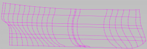
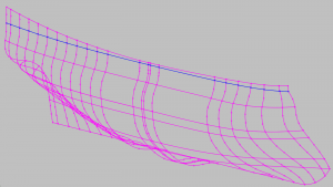
Look at my last 3 images I posted 1st we have just sketches then we have a solid object made from those sketches

Loft is a variant of a wireframe volume of the 3D object, a technique used in 3D modeling packages such as Onshape, 3D Studio Max, Creo*, SolidWorks, and NX. It's developed from planar sections spaced along an approximate path.
Consider lofting in boat building to visualise the process, the planar sections are the boat ribs spaced along its length. The planking then forms the 3D volume as it develops a smooth skin between the ribs.
 
Thanks Joseph for your input as well. My grandfather would have be very pleased that I have learnt 2 things today.
Happy3dmodelling
Greg
 
Thank you Joseph for the tutorial on how to do this I will try my hand at it doing it. You have some Skills Brother. Your explanation makes it sound much easier then it is I'm sure. I guess the first thing is to decide on a program to use for this. Currently I draw up 3D objects in Sketchup and Tinker cad Mostly because there was a big learning curve for me in Fusion 360. I took Mechanical drawing class in school long before things were done on a computer. I could probably hand draw some full size plans from the small drawings I have, but if the programs that create these drawings is anything like some programs I have tried in he past it wont render if there are errors you don't have that luxury in hand drawn plans you find the errors during construction and that's to late. so I'd prefer a good set of Cad plans.

What I have for the constellation spans several books and internet findings showing Frame location and spacing front contour drawing side view top view and I have drawings of the ships hull shape in many places along its length with measurements and lastly a cross section drawing. I probably have enough to be able to build a ship from, but there are a few plans at the national Archives I still need to grab so I have everything available to work with. The ship has gone through some rebuilding in its lifespan and changes were made some quite drastic so I suspect much of the drawings I have are from multiple phases of the ship, they would need to be compared to each other to know what's what. The archive drawings should help greatly to decipher some of the mix up so I want to grab those. I just don't have the time right now to visit them. life's responsibilities have been in the way the past couple weeks I guess I will just have to take a whole day off work to make sure I can get down there.
 
Back
Top