Revenge by OcCre [COMPLETED BUILD]

Joined
Aug 26, 2020
Messages
324
Points
238

Location
UK Dorset
In choosing this build I decided to return to OcCre after excursions to Caldercraft, Corel and Korabel
I like OcCre kits.
They include generous quantities of good quality materials and fittings
The instructions, in the form of coloured pictures of each stage of the build, are very easy to follow.
The limited amount of text required is provided in several languages and the English version is well written.
I have recently learned (from SOS) that full instructions can be downloaded as a pdf file from the OcCre website. I have done that.
The rigging thread is very user friendly: the knots stay knotted and can be secured with a dot of PVA glue. (some
other kits use synthetic thread that seems to need CA glue to secure)
The small fittings come in a useful subdivided plastic box. Two of these from earlier builds have been in constant use since.
This model is very similar to the Golden Hind: the first grown up model I built a few years ago. It will be of personal interest to recall memories of that build to see how acquired experience and an abundance of tools compare.
It seems slightly incongruous that I am building a Spanish kit of Revenge given its history!
I will skip the unpacking part of this log as there are several equivalent examples elsewhere on SOS.
Before initial assembly I recorded measurements of the bulkhead beam width at various heights above the keel to provide input data for a computer program to model the hull shape and design the second layer planking profiles.
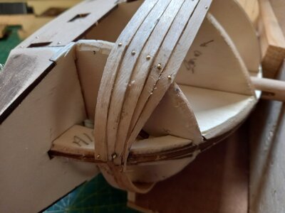
The first layer planking is 2mm thick which seems excessively robust (1.5mm has been the norm in previous builds) but I suppose it will allow for vigorous smoothing before the second stage. As Revenge has fairly bluff bows it deemed a big ask to get these thick planks round to the bow from the first bulkhead - even with soaking and crimping. I did consider stopping at the first bulkhead and filling in the space forward of this with shaped bow blocks. In the end I decided on a different approach. Before fitting the second stage planking it is normal to rub down the first stage planks as they reach the bow and stern to reduce their thickness. I decided that if I did this before applying them they would bend more easily.
The picture below includes a length of wood with a 3mm groove cut with diminishing depth. A plank laid in this groove can be planed off where it protrudes in a controlled manner. The photo shows the model with the first two planks fitted. The required bend at the bow was achieved with no problem.
Revenge1[1].jpg
 
Looking forward to seeing more photos of your build as you progress.

FYI, OcCre has a nice kit which is a tool box with several nice plastic bin stacked and cradle on top to support work, the cradle is removable to lower to desk top for actual work on hull and can be stacked to clear bench if needed.
 
In choosing this build I decided to return to OcCre after excursions to Caldercraft, Corel and Korabel
I like OcCre kits.
They include generous quantities of good quality materials and fittings
The instructions, in the form of coloured pictures of each stage of the build, are very easy to follow.
The limited amount of text required is provided in several languages and the English version is well written.
I have recently learned (from SOS) that full instructions can be downloaded as a pdf file from the OcCre website. I have done that.
The rigging thread is very user friendly: the knots stay knotted and can be secured with a dot of PVA glue. (some
other kits use synthetic thread that seems to need CA glue to secure)
The small fittings come in a useful subdivided plastic box. Two of these from earlier builds have been in constant use since.
This model is very similar to the Golden Hind: the first grown up model I built a few years ago. It will be of personal interest to recall memories of that build to see how acquired experience and an abundance of tools compare.
It seems slightly incongruous that I am building a Spanish kit of Revenge given its history!
I will skip the unpacking part of this log as there are several equivalent examples elsewhere on SOS.
Before initial assembly I recorded measurements of the bulkhead beam width at various heights above the keel to provide input data for a computer program to model the hull shape and design the second layer planking profiles.
The first layer planking is 2mm thick which seems excessively robust (1.5mm has been the norm in previous builds) but I suppose it will allow for vigorous smoothing before the second stage. As Revenge has fairly bluff bows it deemed a big ask to get these thick planks round to the bow from the first bulkhead - even with soaking and crimping. I did consider stopping at the first bulkhead and filling in the space forward of this with shaped bow blocks. In the end I decided on a different approach. Before fitting the second stage planking it is normal to rub down the first stage planks as they reach the bow and stern to reduce their thickness. I decided that if I did this before applying them they would bend more easily.
The picture below includes a length of wood with a 3mm groove cut with diminishing depth. A plank laid in this groove can be planed off where it protrudes in a controlled manner. The photo shows the model with the first two planks fitted. The required bend at the bow was achieved with no problem.
View attachment 340642
well commented
 
Looking forward to seeing more photos of your build as you progress.

FYI, OcCre has a nice kit which is a tool box with several nice plastic bin stacked and cradle on top to support work, the cradle is removable to lower to desk top for actual work on hull and can be stacked to clear bench if needed.
I have known OcCre from its very start in Madrid and got my Montañes before it came on the shelves in 1982/83- until I stopped building I have built 8 different Models. would have liked to get a hand of NTRA. SRA. PILAR -A 1:48
 
A minor mishap.
While fixing the first stage planking I dropped a few pins on the floor. OcCre 'brass' pins are actually plated steel (a good thing; they bend less readily than solid brass) so it was easy to pick them up with a magnet. So far, so good. But while I was removing the collected pins from the magnet to reunite them with their friends I got a bit too close to the tray. It was a very strong magnet. The entire tray contents leaped up to form a spiky ball which looked like a hedgehog on a bad hair day or a new entry to phylum echinoidia. Restoring normality was a slow and painful process.
A knock-on effect of this escapade is that all the pins are now magnetised. This is a mixed blessing: they readily leap to the jaws of my pliers but it is difficult to persuade them that I only want one at a time.
As a postscript to my previous post: I forgot to credit and thank El Capi for that useful tip about OcCre pdf files.
 
In choosing this build I decided to return to OcCre after excursions to Caldercraft, Corel and Korabel
I like OcCre kits.
They include generous quantities of good quality materials and fittings
The instructions, in the form of coloured pictures of each stage of the build, are very easy to follow.
The limited amount of text required is provided in several languages and the English version is well written.
I have recently learned (from SOS) that full instructions can be downloaded as a pdf file from the OcCre website. I have done that.
The rigging thread is very user friendly: the knots stay knotted and can be secured with a dot of PVA glue. (some
other kits use synthetic thread that seems to need CA glue to secure)
The small fittings come in a useful subdivided plastic box. Two of these from earlier builds have been in constant use since.
This model is very similar to the Golden Hind: the first grown up model I built a few years ago. It will be of personal interest to recall memories of that build to see how acquired experience and an abundance of tools compare.
It seems slightly incongruous that I am building a Spanish kit of Revenge given its history!
I will skip the unpacking part of this log as there are several equivalent examples elsewhere on SOS.
Before initial assembly I recorded measurements of the bulkhead beam width at various heights above the keel to provide input data for a computer program to model the hull shape and design the second layer planking profiles.
The first layer planking is 2mm thick which seems excessively robust (1.5mm has been the norm in previous builds) but I suppose it will allow for vigorous smoothing before the second stage. As Revenge has fairly bluff bows it deemed a big ask to get these thick planks round to the bow from the first bulkhead - even with soaking and crimping. I did consider stopping at the first bulkhead and filling in the space forward of this with shaped bow blocks. In the end I decided on a different approach. Before fitting the second stage planking it is normal to rub down the first stage planks as they reach the bow and stern to reduce their thickness. I decided that if I did this before applying them they would bend more easily.
The picture below includes a length of wood with a 3mm groove cut with diminishing depth. A plank laid in this groove can be planed off where it protrudes in a controlled manner. The photo shows the model with the first two planks fitted. The required bend at the bow was achieved with no problem.
View attachment 340642
If I were you, John, I'd remove that first set of planks and place blocks of balsa in the bow and shape them by sanding before you begin planking. As you bend unsupported planked in a sharp curve from the side to the stem, the edges of the planks will often be grossly misaligned. They may be so misaligned that you'll sand right through the hull before the stepped edges disappear. That will really ruin your day.

Also, the planks will assume a hard bend and they pass around Frame #1. That frame will be visible as a vertical bend in the hull. Your hull will look like it has a triangular nosecone instead of one, smooth curve to the stem. WIthout support, any frame that planks curve sharply over will stand out like the ribs on a skeleton after planking and sanding is finished, and you'll have to try disguising that later with many passes of wood filler and sanding. And THAT is a major pain the ass (oh sorry.. Arse! - King's English!). Ask me how I know. I would save you that torment.

Take the time to make filler blocks, and your bow will be glass smooth with little sanding. You'd think by now that all kit instructions would include this basic and important technique. If you want a smooth hull, back the planking in strongly curved areas with balsa blocks. When glued to the blocks as well as the frame edges, the plank edges will be almost perfectly aligned because the curvature of each individual plank will be the same.

In the example below, the entire hull bottom was fill-blocked and shaped. NOT NECESSARY, but filling the heavily double curved bow area is a must. The OcCre Revenge has ZERO support there, and no two planks will bend the same when you try to bend them to the frames. On the sides you can get away with having less support, but not on the bow.

Invest the time to do it this way. You'll thank me later. ;) Thumbsup
And sorry about the lecture!

From this....
1668552351742.png

to this . . .
1668552959660.png

Required filler to flat spots is MINIMAL.
1668553049761.png

After planking and sanding. Smooth curves!
1668553342813.png
 
Last edited:
If I were you, John, I'd remove that first set of planks and place blocks of balsa in the bow and shape them by sanding before you begin planking. As you bend unsupported planked in a sharp curve from the side to the stem, the edges of the planks will often be grossly misaligned. They may be so misaligned that you'll sand right through the hull before the stepped edges disappear. That will really ruin your day.

Also, the planks will assume a hard bend and they pass around Frame #1. That frame will be visible as a vertical bend in the hull. Your hull will look like it has a triangular nosecone instead of one, smooth curve to the stem. WIthout support, any frame that planks curve sharply over will stand out like the ribs on a skeleton after planking and sanding is finished, and you'll have to try disguising that later with many passes of wood filler and sanding. And THAT is a major pain the ass (oh sorry.. Arse! - King's English!). Ask me how I know. I would save you that torment.

Take the time to make filler blocks, and your bow will be glass smooth with little sanding. You'd think by now that all kit instructions would include this basic and important technique. If you want a smooth hull, back the planking in strongly curved areas with balsa blocks. When glued to the blocks as well as the frame edges, the plank edges will be almost perfectly aligned because the curvature of each individual plank will be the same.

In the example below, the entire hull bottom was fill-blocked and shaped. NOT NECESSARY, but filling the heavily double curved bow area is a must. The OcCre Revenge has ZERO support there, and no two planks will bend the same when you try to bend them to the frames. On the sides you can get away with having less support, but not on the bow.

Invest the time to do it this way. You'll thank me later. ;) Thumbsup
And sorry about the lecture!

From this....
View attachment 340843

to this . . .
View attachment 340846

Required filler to flat spots is MINIMAL.
View attachment 340847

After planking and sanding. Smooth curves!
View attachment 340848
After adding a couple more planks I have reached that conclusion too. I shall cut them off at bulkhead 1 and add bow blocks,
 
In choosing this build I decided to return to OcCre after excursions to Caldercraft, Corel and Korabel
I like OcCre kits.
They include generous quantities of good quality materials and fittings
The instructions, in the form of coloured pictures of each stage of the build, are very easy to follow.
The limited amount of text required is provided in several languages and the English version is well written.
I have recently learned (from SOS) that full instructions can be downloaded as a pdf file from the OcCre website. I have done that.
The rigging thread is very user friendly: the knots stay knotted and can be secured with a dot of PVA glue. (some
other kits use synthetic thread that seems to need CA glue to secure)
The small fittings come in a useful subdivided plastic box. Two of these from earlier builds have been in constant use since.
This model is very similar to the Golden Hind: the first grown up model I built a few years ago. It will be of personal interest to recall memories of that build to see how acquired experience and an abundance of tools compare.
It seems slightly incongruous that I am building a Spanish kit of Revenge given its history!
I will skip the unpacking part of this log as there are several equivalent examples elsewhere on SOS.
Before initial assembly I recorded measurements of the bulkhead beam width at various heights above the keel to provide input data for a computer program to model the hull shape and design the second layer planking profiles.
The first layer planking is 2mm thick which seems excessively robust (1.5mm has been the norm in previous builds) but I suppose it will allow for vigorous smoothing before the second stage. As Revenge has fairly bluff bows it deemed a big ask to get these thick planks round to the bow from the first bulkhead - even with soaking and crimping. I did consider stopping at the first bulkhead and filling in the space forward of this with shaped bow blocks. In the end I decided on a different approach. Before fitting the second stage planking it is normal to rub down the first stage planks as they reach the bow and stern to reduce their thickness. I decided that if I did this before applying them they would bend more easily.
The picture below includes a length of wood with a 3mm groove cut with diminishing depth. A plank laid in this groove can be planed off where it protrudes in a controlled manner. The photo shows the model with the first two planks fitted. The required bend at the bow was achieved with no problem.
View attachment 340642
I am also an Occre fan. I have built 16 or their kits, but only one boat - the Ulisses. I have a hand tremor that makes it almost impossible to manage the fine rigging, knots, etc.. So I have been focussed on their trams, trains and buses. I agree with all your comments. They are also very good in replacing missing or broken parts (always in my case, broken by myself!). No questions asked, you just fill out an online parts form and they send it at no charge.
 
Same experiences I am 74 and have been building 50 plus years. Purchases have been selective and always come back to Occre.. I make more mistakes and no eedvmore than normal replacements. Occre ships no questions asked
 
Same experiences I am 74 and have been building 50 plus years. Purchases have been selective and always come back to Occre.. I make more mistakes and no eedvmore than normal replacements. Occre ships no questions asked
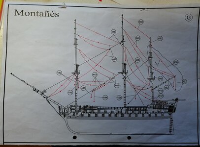
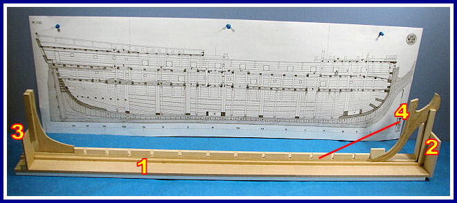
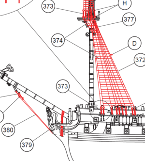
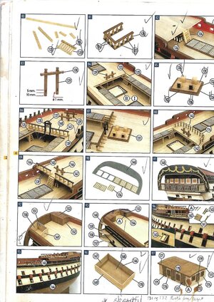
As You can see further up, I was an OcCre builder until I had to stop due to space problems and health reasons. I was when OcCre started in early 1980 living in Madrid, and I got one of the 1Th. Montañes Modelthroug Model eyne- atthat time and still a sahop only dedicater too Model building. stil have the instruction manual from that time

024-SHIPS DRAWING 013.jpg

200-QUILLA-KEEL (1).jpg

1611583791492.png

5.SIDE 5INSTRUCCION MONTAÑES (18) - copia - copia - copia - copia - copia.jpg

4966-sail-squar.jpg

1721--TAYSAILS.jpg
 
A minor mishap.
While fixing the first stage planking I dropped a few pins on the floor. OcCre 'brass' pins are actually plated steel (a good thing; they bend less readily than solid brass) so it was easy to pick them up with a magnet. So far, so good. But while I was removing the collected pins from the magnet to reunite them with their friends I got a bit too close to the tray. It was a very strong magnet. The entire tray contents leaped up to form a spiky ball which looked like a hedgehog on a bad hair day or a new entry to phylum echinoidia. Restoring normality was a slow and painful process.
A knock-on effect of this escapade is that all the pins are now magnetised. This is a mixed blessing: they readily leap to the jaws of my pliers but it is difficult to persuade them that I only want one at a time.
As a postscript to my previous post: I forgot to credit and thank El Capi for that useful tip about OcCre pdf files.
Been there, done that, but no Tee shirt!
 
First Stage Planking
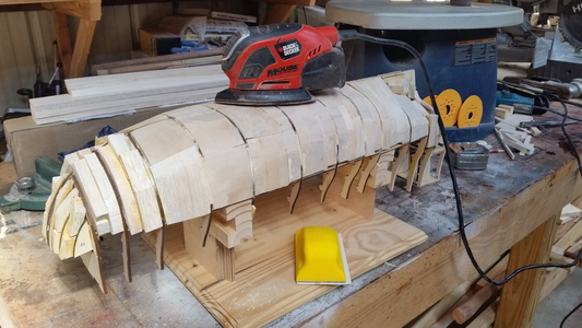
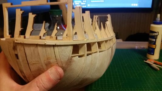
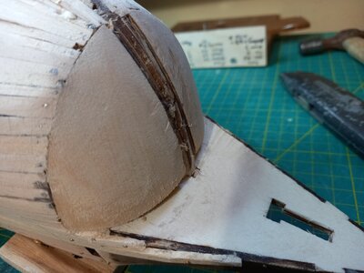
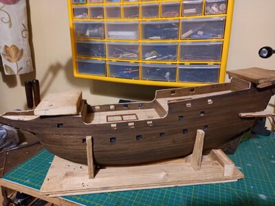
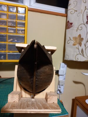
I have decided to emulate our politicians by executing a U turn. After trying to bend a few first layer planks round to the bow I ran into the usual problems of extreme tapers and crowding (first picture) so it is back to the original plan of fitting bow blocks back to the first bulkhead. I made these from lime rather than balsa so they are firm enough not to need first layer planking over.
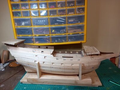
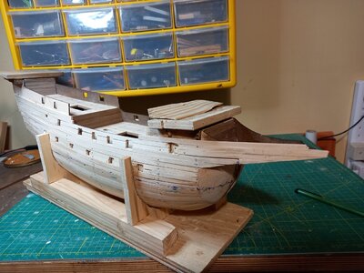
The first layer planking is now almost complete. Some final robust sanding is needed. I have bought some cintride discs that make short work of the protruding pin heads. The crude additions to poop an forecastle are temporary measures to keep the model stable and level when inverted.
I am about to start on the experimental use of shaped planks cut from a sheet of walnut for the second layer. More on this later.Bow Planking.jpg Bow Blocks.jpg
planks1a.jpg planks1b.jpg
 
Second stage planking.
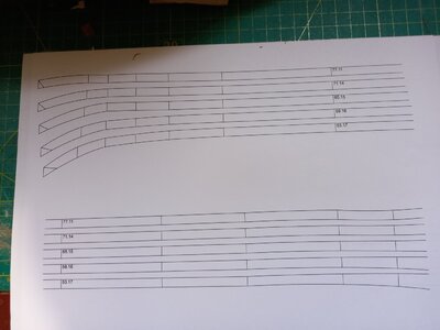
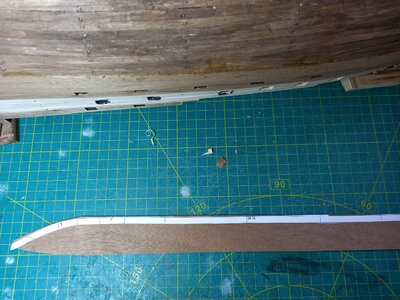
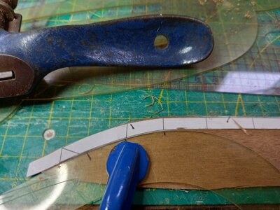
The sequence of photos below show the stages of preparing shaped planks to keep the seams roughly parallel to the keel rather than turning up excessively towards the bow.
1. Print out a batch of (five) planks from the computer model.
2. Cut a paper version of the plank and test it on the hull. Mark any minor adjustments needed.
3. Paste the paper plank on a pair of sheets of 1mm walnut. Trim the top edge with plane/spokeshave/whatever.
4 Using appropriate sections of French/Ship's curves as a guide cut out a pair of planks.
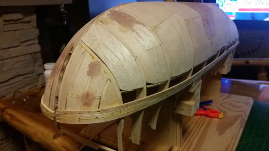
Soak, crimp, bend and fit the planks using contact adhesive. I have crudely stained the lime planks of the first layer so that they will not be too visible through any chinks in the second layer planks. The second picture below shows the first five planks in place. I have left a bit of an overlap at the stem to be trimmed later. The principle seems to be working out fairly well; the computer modelling seems to be getting it about right - though the very forward tip of the planks is a bit beyond its capability where a curve in the plane of the keel (the stem), a curve in a plane parallel to the bulkheads and a curve in the plane parallel to the decks all meet. When cutting a plank I have simply extrapolated the top and bottom edges from the more reliable section just aft of the bow with a bit of a run out for trimming.
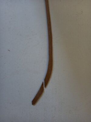
Lower down the hull a problem emerged when the curve of the planks became too inconsistent with the grain of the wood. (final photo). I resolved this by cutting the first few cm of the plank as a separate section laid more favourably with the grain.
The process is a little bit more complicated than using conventional planking strips but makes an interesting change and challenge. Nothing like as tedious as tying ratlines! I think the final result , when trimmed, sanded and varnished will be quite pleasing.
Printout.jpg Papertest.jpg Paste.jpgCut.jpg
Break.jpg
 
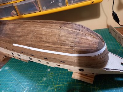
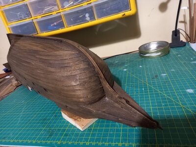
Second stage planking complete.
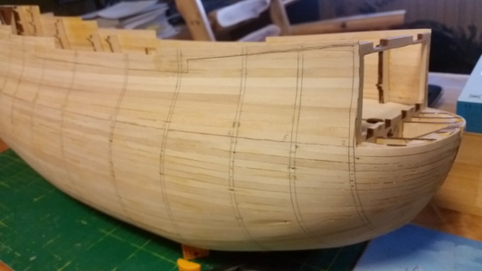
The fitting of shaped second stage planking seems to have gone according to plan. It has successfully avoided the rising cluster of pointed planks at the stem. With hindsight I could have made the planks a bit narrower. I aimed for a basic 6mm width rather than the more common 5mm to reduce the number of seams because I wasn't sure how easily the shaped planks would join and how much trimming would be required. In practice the computer modelling gave curves that fitted well with minimal adjustment. I cut planks that were shaped only forward of the widest bulkhead. Having seen the lie of the first stage planking (uniform 5mm strips) I decided that a uniform 6mm width for the second stage planking would be mainly OK aft of the that point. When approaching points where the first stage planking required spreaders I simply widened the second stage planks a bit as they approached the stern. The computer modelling of planks parallel to the keel (with allowance for the curve of the gun port line at the higher levels) produced some rather bizarre shapes when trying to keep the seams absolutely level round the bottom of the transom. I ignored this. The lowest five or so planks at the approach to the keel were shaped in situ rather than being modelled. As with other attempts to use a new technique when ship modelling, the experience gained here will allow me to de better next time.
In summary: the shaping of planks at the bow to counter the tendency for them to turn upwards has been successful and required little more effort than that needed to taper uniform strips and insert drop planks. Elaborate shaping towards the stern is not necessary.
planked1.jpg planked3.jpg planked4.jpg
 
Gun Tackles
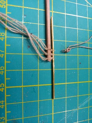
I have evolved a reasonably efficient way of producing small blocks for gun tackles that are more consistent with the scale of the carriages than the blocks supplied with the kit. In the picture below:
The brass rod is used for those blocks that require an eye on the strop. The wooden strip is 3x2 mm with the corners rounded.. The strop, with extensions for later tying to eyebolts, is glued and knotted round the wooden strip. A batch can be tied before cutting off the individual blocks.
Before cutting off the end block the strip is trimmed as close as possible to the strop and a hole drilled into the end roughly as far as the block thickness. A block - complete with hole, strop and loop - is then cut from the wooden strip and slipped off the brass rod.
This sequence avoids having to handle, drill and bind a very tiny piece of wood. I need 48 of these - half without a loop on the strop.
small blocks.jpg
 
Gun Tackles
I have evolved a reasonably efficient way of producing small blocks for gun tackles that are more consistent with the scale of the carriages than the blocks supplied with the kit. In the picture below:
The brass rod is used for those blocks that require an eye on the strop. The wooden strip is 3x2 mm with the corners rounded.. The strop, with extensions for later tying to eyebolts, is glued and knotted round the wooden strip. A batch can be tied before cutting off the individual blocks.
Before cutting off the end block the strip is trimmed as close as possible to the strop and a hole drilled into the end roughly as far as the block thickness. A block - complete with hole, strop and loop - is then cut from the wooden strip and slipped off the brass rod.
This sequence avoids having to handle, drill and bind a very tiny piece of wood. I need 48 of these - half without a loop on the strop.
View attachment 350573
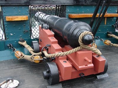
Before you get too far along, be advised that there are hooks on each of the blocks in a gun tackle that engage eyes or rings on the carriage and on the bulwark. That way, the gun tackles can be taken off, sometimes to be used as train tackles. The trick is knowing how much detail to sacrifice as the scale of the guns gets smaller.

Cannon USS Constitution.jpg
 
Gun Tackles
I have evolved a reasonably efficient way of producing small blocks for gun tackles that are more consistent with the scale of the carriages than the blocks supplied with the kit. In the picture below:
The brass rod is used for those blocks that require an eye on the strop. The wooden strip is 3x2 mm with the corners rounded.. The strop, with extensions for later tying to eyebolts, is glued and knotted round the wooden strip. A batch can be tied before cutting off the individual blocks.
Before cutting off the end block the strip is trimmed as close as possible to the strop and a hole drilled into the end roughly as far as the block thickness. A block - complete with hole, strop and loop - is then cut from the wooden strip and slipped off the brass rod.
This sequence avoids having to handle, drill and bind a very tiny piece of wood. I need 48 of these - half without a loop on the strop.
View attachment 350573
WELL DONE MATE. AT LEAST SOME GOOD INFO AND NOT INFO ABOUT BUILDING A SWIMMING POOL
 
Gun Carriage axles
The OcCre kit provides some 1.5mm brass rod from which to cut axles for the gun carriages. I'm not keen on this option. The quickest way to cut the 28 segments would be using a pair of side cutting pliers but this would leave rather battered ends. A cleaner cut would require repeated use of a hacksaw and/or some filing. Gluing brass axles to the wooden trucks and carriages would probably require CA glue. Even with a gel I find it doesn't stick very well to wood over a small contact area.
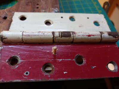
A preferred option is to make wooden axles. With no obvious source of 1.5 mm dowel I started with cocktail sticks. I drilled 2mm, 1.8mm and 1.6mm holes in an old door hinge - a convenient piece of soft iron. Short lengths of cocktail sticks were driven through each hole in succession. This effectively shaved them down to a snug fit in the supplied trucks. Fixing to the carriages could now be done using PVA glue.
Axles.jpg
 
Gun Carriage axles
The OcCre kit provides some 1.5mm brass rod from which to cut axles for the gun carriages. I'm not keen on this option. The quickest way to cut the 28 segments would be using a pair of side cutting pliers but this would leave rather battered ends. A cleaner cut would require repeated use of a hacksaw and/or some filing. Gluing brass axles to the wooden trucks and carriages would probably require CA glue. Even with a gel I find it doesn't stick very well to wood over a small contact area.
A preferred option is to make wooden axles. With no obvious source of 1.5 mm dowel I started with cocktail sticks. I drilled 2mm, 1.8mm and 1.6mm holes in an old door hinge - a convenient piece of soft iron. Short lengths of cocktail sticks were driven through each hole in succession. This effectively shaved them down to a snug fit in the supplied trucks. Fixing to the carriages could now be done using PVA glue.
View attachment 350898
I like your solution very much. Many times we do not see the Forrest, due to all the trees in front- I am from the OLD SCHOOL- el CApi
 
Back
Top