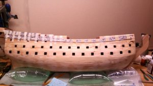
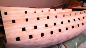
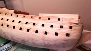
Royal William Euromodel 1:72 by Vince P. -- FINISHED

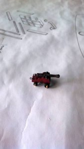
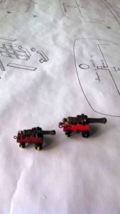
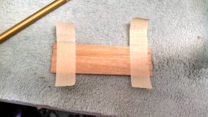
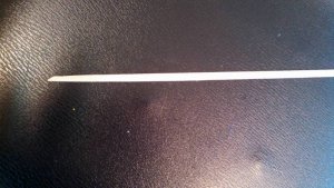
I obtained some 2.0mm wide x 0.3mm copper strip from Ages of Sail. I cut it to 9.0mm length and bent it around a 1.5mm drill bit to make the trunnion band for the gun carriages. It came out pretty good, but the photo is a little blurry (crappy camera).

Vince P. Ship-1

View attachment 65860
Vince,
A bit too late, but... I make my brass strips from plates which are available on eBay. Any thickness between 0.05 mm and 2 mm available - being this our range. Then I cut strips of it on the circular saw, with a 'metal' blade (can also be used for cross-cuts in timber). Cheaper, the exact size what is needed and you don't have to wait for the strip delivery. For convenience I put masking tape on both sides of the plate before cutting.
Janos
 
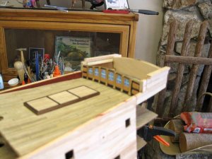
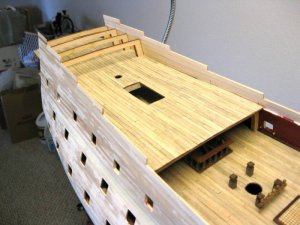
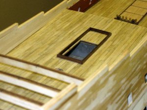
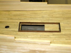
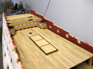
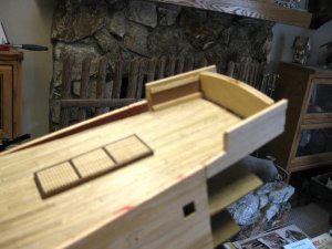
There is a huge difference in the dimensions of the grating opening on the quarterdeck between the plans and the cutout provided in the false deck. As you can see by the photos, the cutout is much shorter than the frame I installed. The frame matches the size in the plans, which I chose to follow. The grating will be separated into 3 equal sections. I also noted that the grating on the upper quarterdeck has the same issue.

Vince P. Ship-1

pict0164.JPGpict0165.JPG
 
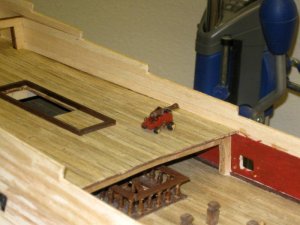
Before making the gunport cutouts on the quarterdeck and forecastle, it is necessary to make up at least one deck gun in order to get the correct height of the ports off the deck. You shouldn't just use the plans, although they were right on at 11.5mm from the deck to the center of the ports.
These guns are smaller than the main deck guns and somewhat of a challenge to construct. If you are going for detail such as the cotter pins in the trucks, drilling such small holes without splitting the wood was a fun project. I used the pieces of brass pin cut off some of the eye bolts, as they were a perfect size (0.5mm) diameter. The drill size was a #76.

Next up is to make the gunport cutouts.

Vince P. Ship-1

pict0167.jpgpict0168.jpgpict0166.JPG
 
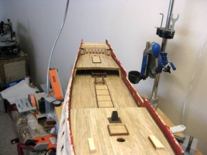
The quarterdeck is complete with gratings, waterways, and gunport cutouts. The bulkhead to support the upper quarterdeck is also painted and installed.
Next up is the upper quarterdeck.
In this area and further in is where things get a little foggy with this build. There are many discrepancies between the plan drawings and the parts supplied. It is going to take some research to figure it all out. Then comes the dreaded "Round Staircase". There are so many versions out there and all very difficult to construct. I am working on a plan as we speak.

Oh, I got a promotion! I am now a Lieutenant Commander. Not sure what I did, but I must deserve it.

Vince P. Ship-1

pict0169.JPGpict0170.JPGpict0171.JPG
 
Please take a look also at the topic "Naval History" dated two days ago, with the history of the HMS Royal Prince (launched at 3rd December) and after her rebuilt to HMS Royal William with a lot of contemporary drawings and beautiful models built in 1720 from the National Maritime Museum:

https://www.shipsofscale.com/sosfor...ime-events-in-history.2104/page-67#post-46833
and
https://www.shipsofscale.com/sosfor...ime-events-in-history.2104/page-67#post-46834

Thanks for the great links. Lots of info and photos for both the Prince and Royal William. I will use for reference for both builds.

Vince P. Ship-1
 
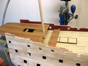
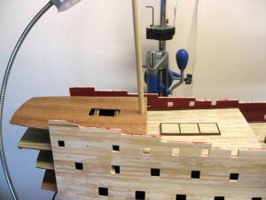
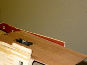
Ok, here is what I mean by differences between the plan drawings and the provided parts. The first photo shows the false upper quarterdeck laying in place with the piece cut off of it to match the plans.
I trimmed the side edges so it makes a clean fit along the bulwarks and placed the mizzen mast to make sure it is positioned through the hole properly with the correct cant.
The deck is just laying on the frames at this point. According to the plans, the bottom of the forward edge needs to be 23.5mm from the top of the quarterdeck below. A breast beam needs to be fabricated and placed just aft of the edge to support the deck and secure the correct height.

Vince P. Ship-1

pict0172.JPGpict0173.JPGpict0174.JPG
 
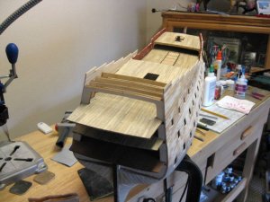
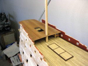
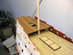
The upper false quarterdeck is secured in place. Before planking it, the bulwarks that run partially on this deck need to be cut back substantially because the forward end actually falls slightly below the deck surface itself.
This is where you really have to pay attention to the plan drawings. Sheet #17 shows the run of the decks and the hull detail in scale. Making careful measurements off the drawing is needed to mark the bulwarks for cutting.
The first photo shows the bulwark before and the second after cutting back.

Vince P. Ship-1

pict0174.JPGpict0175.JPG
 
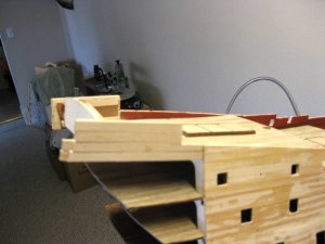
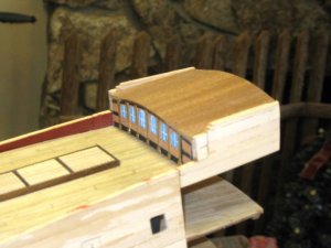
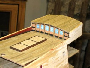
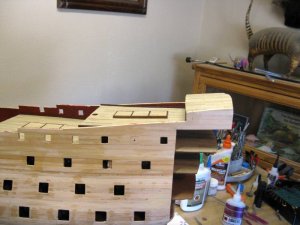
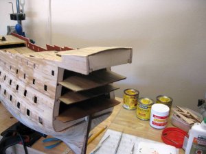
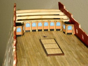
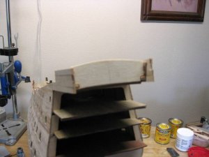
Working on and finishing the last deck, the poop deck. This was by far the most difficult part of the build so far. Unlike all of the other decks that are supported by the bulkhead frames, this deck has no real support. The kit comes with 2 small pieces of plywood made from the same wood as the false decks. These are to be glued in a vertical position on the upper quarterdeck to support the poop. That to me was not a satisfactory option, as it offered little support to the deck.
I constructed a bulkhead for the aft end and side supports to link the forward metal bulkhead and aft bulkhead . When I planked the hull at the aft end at the level of the upper quarterdeck and above, I should have extended the planks past the last hull bulkhead by at about 100mm. I cut them off flush with the last bulkhead, which meant I had to extend them aft to support the poop that hangs over the aft edge of the upper quarterdeck for most of its length. Oh well, you live and learn.
The exact horizontal location of the deck, its height from the upper quarterdeck below, the vertical slope, and the camber all required considerable measurements between plan sheets 2 and 17. These sheets do not exactly agree, so a compromise had to be made, and I hope I guessed correctly.
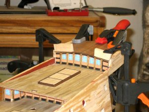
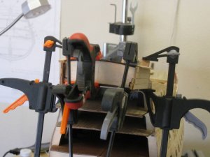
The false deck and the metal forward bulkhead had to be modified considerably in length, height, and shape. Once the false deck was placed on the frame, it had to be bent considerably at both ends to provide the heavy camber and required some serious clamping.

Also on another note: If you are planning on using the larger dimensions for the deck gratings as the plans show and not the smaller sizes as per the cutouts on the decks, you will not have enough grating pieces. There are enough to do the decks, but not to do the quarterdeck overhang and the heads at the bow. More will have to be acquired.

Next up is to prepare the hull for the finish layer of second planking. Since the finish layer is only going up to the bottom edge of the metal hull decorations from bow to stern, all of the pieces have to be placed temporarily in their exact locations to mark the upper boundary for the planking layer.

Vince P. Ship-1

pict0176.JPGpict0177.JPGpict0178.JPGpict0179.JPGpict0180.JPGpict0181.JPGpict0182.JPGpict0183.JPGpict0184.JPGpict0185.JPG
 
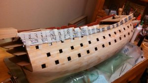
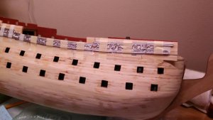
I taped all of the decorative metal pieces on the starboard side to get a run on the hull. It took much juggling to get all of them in the proper locations and required a lot of measuring from plan sheets 2 and 17. The design pieces have built in indentations where they intersect the gunports. It was very difficult to get them all lined up with no gaps. I am amazed that the gunport location accuracy was close enough to match the metal panels. I then drew a line along the bottom edge from stern to bow and removed the pieces. This line delineates the top border of the second finish layer of planking. I will now do the same to the port side.

Vince P. Ship-1
pict0186.jpgpict0187.jpgpict0188.jpgpict0189.jpgpict0190.jpg
 
Outlining the hull for the finish second layer of planking.
I have a specific method I use which works for me. There are many methods that work well. I did not invent this method, just like it better and copied it from another builder who was kind enough to publish an article in a magazine.

1. Invert the hull.

2. Divide the hull into 5 plank wide bands by taping 5 short pieces of planking wood side by side and starting from the keel, tape them to the hull midships where the planks will run parallel to the keel and at full width. Draw a pencil line at the lower edge.

3. Place the taped short strips on the pencil line and repeat all the way down the hull. Depending on the size of the hull, you may have as many as 6 or more bands.

4. Place a full length plank on the bottom of each line and tape it in a natural run so as not to twist it or bend it .

5. Draw a pencil line along the top from stem to stern.

6. Repeat for each short pencil line.

You can now see how the planks run and where they will need tapering and where they will need filling in between them at the stern. By measuring between the lines at any point along a band and dividing by 5 will give you the width of each plank at that point.

Vince P. Ship-1
pict0191.jpgpict0192.jpgpict0193.jpgpict0194.jpgpict0195.jpgpict0196.jpgpict0197.jpgpict0198.jpgpict0199.jpg
 
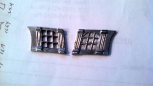
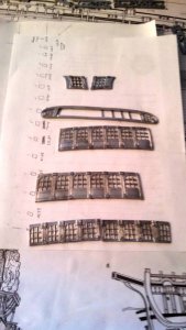
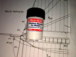
The metal castings that make up the gallery windows are OK, but the windows don't look good even when painted. I decided to cut out the window panes and will fill them in with a clear film that should look like real windows. I don't have a fancy milling machine, so I will cut them out by hand. There are literally about 100 windows, so this should take a long time. The first photo shows the original windows and the cut out windows. I have some liquid glass that you just dab on and it dries to clear glass. The second photo just shows the amount of rear windows and not the larger amount of side windows.

The windows are made of a soft cast pot metal. To cut them out I used a diamond bit in a Dremel tool. You have to be careful not to melt the frames, so I keep dunking them in water when they get warm. It takes about a half hour to do each frame. There are about 40 frames. o_O

Vince P. Ship-1
pict0255b.jpgpict0255c.jpg
 
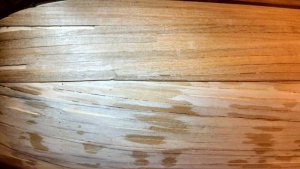
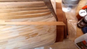
As the planking gets close to the bow, the width of some of the planks almost come to a point. The rule is to not allow the width to get less than one half of the full starting width. This is because there is no way to firmly secure them with trenails if they get too thin. The fix was to use "Joggle Planks" At the end where two or three planks come almost to a point, simply lay one plank over the space and them run it down a short distance until it would be almost full width. Then run the two or three planks that join it together. See photo. There may be several of these in various sizes that will be needed.

Vince P. Ship-1
pict0203.jpgpict0204.jpgpict0205.jpg
 
As you get to the stern end, the planks fan out creating spaces. These need to be filled in with planks called "Stealers". Since you should not terminate a plank into a point, it is necessary to notch the plank it will butt up to. Again, there will be a number of these needed of various sizes.

Vince P. Ship-1
pict0202.jpgpict0200.jpg
 
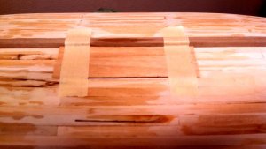
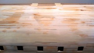
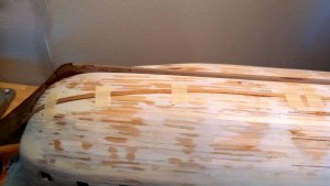
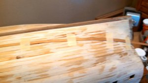
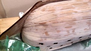
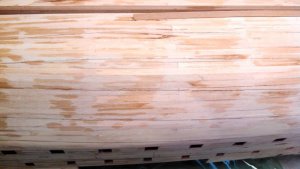
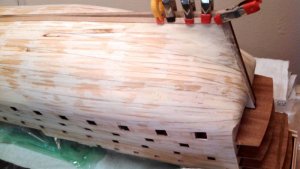
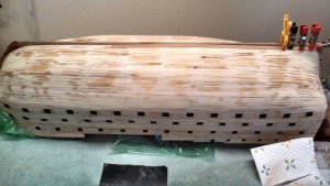
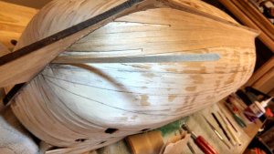
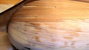
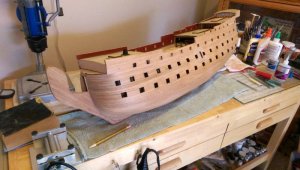
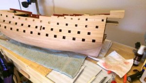
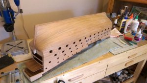
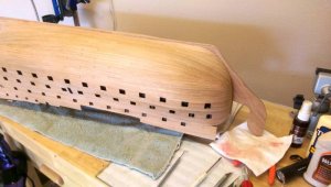
I finally completed the second finish layer of planking. That seemed to take forever. It has only been sanded but not sealed or stained and painted yet.

Remember before, I stated that I placed all of the metal decoration pieces along the hull sides and drew a line under them where the second finish layer of planking would stop. Well that idea was scrapped because of two reasons. First, the run of the planking did not follow this line which would require cutting small thin strips of planking in various locations in order to butt up cleanly again the metal pieces. This is not realistic. Secondly, when the metal pieces butted up against the end of the planking, half of the depth of the metal pieces would be lost. This would take away from the contrast of the decorations against the hull because they wouldn't stand out as much. So, I ran the second planking all the way up to the top.

Next up is to install the gun port linings. That will also be a monumental task as each lining consists of 4 pieces. I will use some of the leftover walnut planking strips.

Vince P. Ship-1
pict0210.jpgpict0211.jpgpict0212.jpgpict0213.jpg
 
Gonna try that planking on my next build. Hope i understand this enough to make it work for me. Wat is the name of that liquid glass? Looks good.
Hi Pat,
If you get stuck on trying to figure it out, just shoot me a message and I will help you sort it out.

The glass is called Micro-Glaze. I bought it from Micro-Mark on line.

Vince P. Ship-1
Micro-Glaze.jpg
 
Back
Top