You're doing a phantastic job Alexander.

-

Win a Free Custom Engraved Brass Coin!!!
As a way to introduce our brass coins to the community, we will raffle off a free coin during the month of August. Follow link ABOVE for instructions for entering. -

SUBSCRIBE TO SHIPS IN SCALE TODAY!
The beloved Ships in Scale Magazine is back and charting a new course for 2026!
Discover new skills, new techniques, and new inspirations in every issue.
NOTE THAT OUR NEXT ISSUE WILL BE MARCH/APRIL 2026
You are using an out of date browser. It may not display this or other websites correctly.
You should upgrade or use an alternative browser.
You should upgrade or use an alternative browser.
Saint Albans 1687 in Navy Board Style - 1 : 48 scale [COMPLETED BUILD]
- Joined
- Apr 10, 2019
- Messages
- 220
- Points
- 253

Hi Alexander
A realy pretty work, well done
Willi (schifferlbauer)
A realy pretty work, well done
Willi (schifferlbauer)
It continues with the carlings of the Gundeck. These are very close at the Saint Albans.
According to Franklin, there are the following methods to fix the carlings in the ledges (sheer sticks). I decided on method C given the 120+ carlings.

In order to align the carlings parallel and symmetrically, I made simple spacers that have different thicknesses.

So the work went smoothly. After all, there were 10 meters of wooden strips for the carlings alone.


The gratings of the gundeck are built with the standard method. That was much easier than the method with drilled holes in end grain wood. But the gundeck will hardly be visible later, so it doesn't matter here. The same applies to the side strips with the deck planking. I simply covered this with the planks and not from whole wooden boards, as probably on the original. The middle pieces are, however, very well boards in which the course of the planks has been engraved with a steel needle. The material for the planking is hornbeam.


I realized the caulking for the first time with an oil paint washing with green Bohemian soil (Grüne Böhmische Erde). This technique is used in plastic model making to highlight the fine engravings. In preparation, I sealed the planking twice with Clou Primer (Schnellschleifgrund), so that a smooth surface is created. Then I brushed the diluted oil paint on over a large area. The color is then full in the grooves between the planks. After the paint has dried slightly - after approx. 15 minutes - the plank surfaces are cleaned with a cloth soaked in turpentine. The color remains in the grooves. That worked well and the effect is quite realistic.

Here are a few more gadgets that were helpful with the work. Metal sanding shoes with replaceable plastic ribbing. Are easy to handle and works fast.
Steel needle, steel ruler, graver and needle file for engraving the planks
Greetings, Alexander
According to Franklin, there are the following methods to fix the carlings in the ledges (sheer sticks). I decided on method C given the 120+ carlings.
In order to align the carlings parallel and symmetrically, I made simple spacers that have different thicknesses.
So the work went smoothly. After all, there were 10 meters of wooden strips for the carlings alone.
The gratings of the gundeck are built with the standard method. That was much easier than the method with drilled holes in end grain wood. But the gundeck will hardly be visible later, so it doesn't matter here. The same applies to the side strips with the deck planking. I simply covered this with the planks and not from whole wooden boards, as probably on the original. The middle pieces are, however, very well boards in which the course of the planks has been engraved with a steel needle. The material for the planking is hornbeam.
I realized the caulking for the first time with an oil paint washing with green Bohemian soil (Grüne Böhmische Erde). This technique is used in plastic model making to highlight the fine engravings. In preparation, I sealed the planking twice with Clou Primer (Schnellschleifgrund), so that a smooth surface is created. Then I brushed the diluted oil paint on over a large area. The color is then full in the grooves between the planks. After the paint has dried slightly - after approx. 15 minutes - the plank surfaces are cleaned with a cloth soaked in turpentine. The color remains in the grooves. That worked well and the effect is quite realistic.
Here are a few more gadgets that were helpful with the work. Metal sanding shoes with replaceable plastic ribbing. Are easy to handle and works fast.
Steel needle, steel ruler, graver and needle file for engraving the planks
Greetings, Alexander
Last edited:

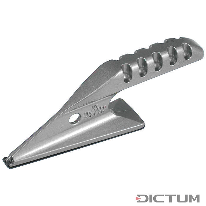
Very interesting tools - where did you get these sanding shoes?
BTW: Very good work.
BTW2: I can fully understand that you made the lower deck not so detailed or with different slightly "easier" methods, due to the fact, that this will be hardly visible later on......When I saw first the photos, before reading your text, I was asking myself, why the gratings have not a complete framing in which the gratings are sitting......
It is looking very good my friend
Hi Uwe
The sanding shoes are made in Japan and I got them from Dictum
 www.dictum.com
Cheers, Alexander
The sanding shoes are made in Japan and I got them from Dictum
Präzisions-Handschleifer NT, Schleifschuh dreieckig, spitz | Feilen für Holz- und Holzwerkstoffe | Dictum
Präzisions-Handschleifer NT, Schleifschuh dreieckig, spitz | Feilen für Holz- und Holzwerkstoffe | Dictum
Cheers, Alexander
- Joined
- Apr 10, 2019
- Messages
- 220
- Points
- 253
Hi Alexander
Great work , well done
Regards
Willi (schifferlbauer)
Great work , well done
Regards
Willi (schifferlbauer)
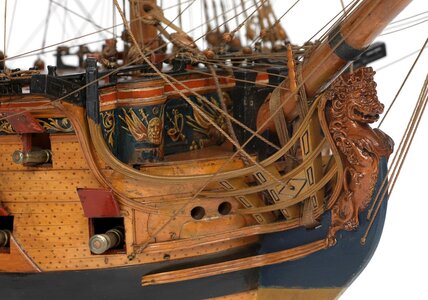
I wanted to build the ornated hawser lining now. This raises the question of the size of the holes in it.
The plan shows that the right hole is much smaller than the other three.

I straightened out the plan detail. Then the two hawsers look like this.

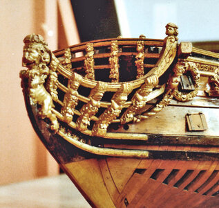
You can see at the photos of the original model from the Trinity House that this is not a mistake in the plan.

The asymmetry is really strong. What's your opinion on that? Would you also do it so that only one hole is smaller? Or do you see a mistake there?


Otherwise I have now also prepared the beams of the upper gun deck. The camber of this deck is much stronger than that of the lower deck. The long carlings are again very high and thus also form the coaming of the hatches. The assembly has to wait a bit, because the capstans have to be installed first.
Cheers, Alexander
The plan shows that the right hole is much smaller than the other three.
I straightened out the plan detail. Then the two hawsers look like this.
You can see at the photos of the original model from the Trinity House that this is not a mistake in the plan.
The asymmetry is really strong. What's your opinion on that? Would you also do it so that only one hole is smaller? Or do you see a mistake there?
Otherwise I have now also prepared the beams of the upper gun deck. The camber of this deck is much stronger than that of the lower deck. The long carlings are again very high and thus also form the coaming of the hatches. The assembly has to wait a bit, because the capstans have to be installed first.
Cheers, Alexander
Last edited by a moderator:
I think, that the modeler of the contemporary model made a mistake (maybe he broke the thicker drill and had no spare with the correct diameter ") )
)
But based on the weight of the anchors, the anchor cables were partly different, so it could be, that the different diameters of the holes are because of this.
I never realized it and not often shown on models
)But based on the weight of the anchors, the anchor cables were partly different, so it could be, that the different diameters of the holes are because of this.
I never realized it and not often shown on models
- Joined
- Apr 10, 2019
- Messages
- 220
- Points
- 253
Hi Alexander
I´m thinking like Uwe the drawing is a mistake. I compared some models and the hawser holes are of the same size.
I´m thinking too it makes no sense to make different holes in size, but it could be that by some models it is so.
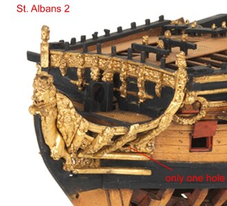
By the photographs of the 2. model of ST. ALBANS i see only one hole. I send you pictures.
Kind regards
Willi (schifferlbauer)
I´m thinking like Uwe the drawing is a mistake. I compared some models and the hawser holes are of the same size.
I´m thinking too it makes no sense to make different holes in size, but it could be that by some models it is so.
By the photographs of the 2. model of ST. ALBANS i see only one hole. I send you pictures.
Kind regards
Willi (schifferlbauer)
Attachments
-
 ankerklüsen 1 (Large).jpg297.3 KB · Views: 27
 -
 Ankerklüsen 2 (Large).jpg253.4 KB · Views: 26
 -
 Ankerklüsen 3 (Large).jpg109.3 KB · Views: 23
 -
 Ankerklüsen 4 (Large).jpg331.1 KB · Views: 24
 -
 Ankerklüsen 5 (Large).jpg195.9 KB · Views: 23
 -
 Ankerklüsen 7.jpg243.2 KB · Views: 22
 -
 Ankerklüsen 6 (Large).jpg217 KB · Views: 25
Thanks Uwe and Willi!
Thanks also for the Likes!
Willi, please note, the picture of the Trinity-Model shows definitly one larger and one smaller hole at the port side. According to Read's plan.

Cheers Alexander
Thanks also for the Likes!
Willi, please note, the picture of the Trinity-Model shows definitly one larger and one smaller hole at the port side. According to Read's plan.
Cheers Alexander
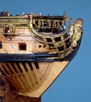
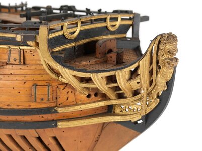
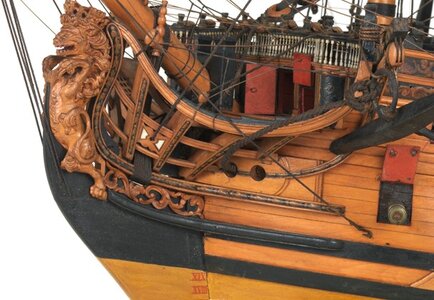
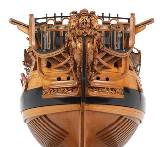
In the meantime I have reworked the gunport wreaths and also prepared the lids.
It looks like this with the fittings.
The pins are still missing, which are pretty tiny at 0.5 mm in diameter and 1.5 mm in length.

Cheers, Alexander
It looks like this with the fittings.
The pins are still missing, which are pretty tiny at 0.5 mm in diameter and 1.5 mm in length.
Cheers, Alexander
Hallo Alexander,
I think the reworked wreaths are much better, than the first one you showed earlier..... much better
Are they also made out of silicon based on a new carved original?
Also the hinges are very good - same size like on the contemporary model ->
I think the reworked wreaths are much better, than the first one you showed earlier..... much better
Are they also made out of silicon based on a new carved original?
Also the hinges are very good - same size like on the contemporary model ->
Hi Uwe
that are the ones I made of resine.
Grüße, Alexander
that are the ones I made of resine.
Grüße, Alexander
- Joined
- Apr 10, 2019
- Messages
- 220
- Points
- 253
Hi Alexander
The gun port wreaths are now in the stile of the contemporary models and look pretty well.
Kind Regards
Willi (schifferlbauer)
The gun port wreaths are now in the stile of the contemporary models and look pretty well.
Kind Regards
Willi (schifferlbauer)

This model is truly inspirational. Well done. ")

17th century warships are truly beautiful.
You are creating a work of art with the St Albans.
You are creating a work of art with the St Albans.
Hi Alexander,Thanks Uwe and Willi!
Thanks also for the Likes!
Willi, please note, the picture of the Trinity-Model shows definitly one larger and one smaller hole at the port side. According to Read's plan.
View attachment 183593
Cheers Alexander
The smaller hawser hole is most probably not a mistake.
The size of the hawser hole is in relation to the anchor cable that it is used for.
These ships had three large anchors, the sheet anchor, the bower and the best bower anchors of nearly equal size, then a spare anchor, stream achor, kedge anchor which all were much smaller.
The best bower was kept on PS side, the bower on SB side, as well as the sheet anchor. These had similar size cables but the smaller size anchors could be handeled with smaller cables and therefore a smaller hawse hole. Guess your smaller hawse hole is situated on the PS side?
It was purposed for the smaller stream and kedge anchors which carried smaller cable sizes.
Hi Maarten,
thanks for the explanation. This explains the asymmetry. The small hole is at the port side indeed.
Cheers Alexander
thanks for the explanation. This explains the asymmetry. The small hole is at the port side indeed.
Cheers Alexander
In the meantime I carved and attached the hawswe-timbers.


Making the capstans:
In preparation, 10 triangular strips of pearwood with an angle of 36 ° were made and glued in a circle.


This was turned on the lathe.
Unfortunately pictures of the finished parts are missing.
The result looks like this:

The left capstan is on the lower gundeck. The abutment extends to the orlop deck on the ship. Since this deck is missing on the model, there is a simple construction that is attached to the keelson. The capstan is fastened in this construction.
The right capstan extends from the lower to the upper gundeck. This upper part will then be visible on the finished model. However, metal fittings are also missing on the original model. Only the pawls are present.
Cheers Alexander
Making the capstans:
In preparation, 10 triangular strips of pearwood with an angle of 36 ° were made and glued in a circle.
This was turned on the lathe.
Unfortunately pictures of the finished parts are missing.
The result looks like this:
The left capstan is on the lower gundeck. The abutment extends to the orlop deck on the ship. Since this deck is missing on the model, there is a simple construction that is attached to the keelson. The capstan is fastened in this construction.
The right capstan extends from the lower to the upper gundeck. This upper part will then be visible on the finished model. However, metal fittings are also missing on the original model. Only the pawls are present.
Cheers Alexander
Last edited:
- Joined
- Apr 10, 2019
- Messages
- 220
- Points
- 253
Hi Alexander
The Hawswe timbers are well made and fits pretty good . The capstan too.
Friendly regards
Willi (schifferlbauer)
The Hawswe timbers are well made and fits pretty good . The capstan too.
Friendly regards
Willi (schifferlbauer)