Scratchbuild Creole Queen

  • Thread starter Thread starter Ferd
  • Start date Start date
  • Watchers Watchers 3
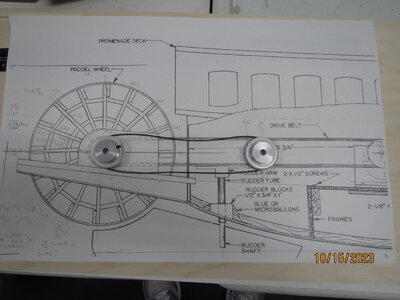
Paul, I think I'm ready to order timing pulleys and a belt, but I have a question about that. The CQ kit uses a very narrow O-ring pulley on the paddle wheel, but my timing pulley will be almost 3/4" wide and won't fit. What are you changing to solve this problem? Are you making the complete wheel a bit narrower?
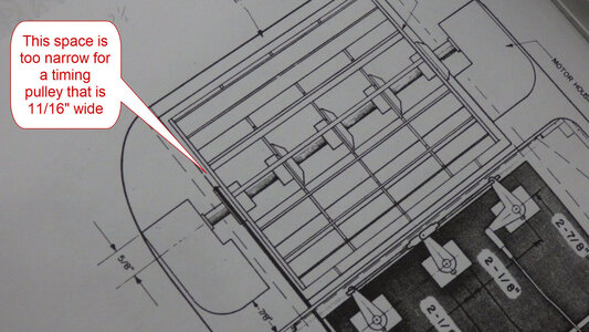
Timing Pulley.JPG
 
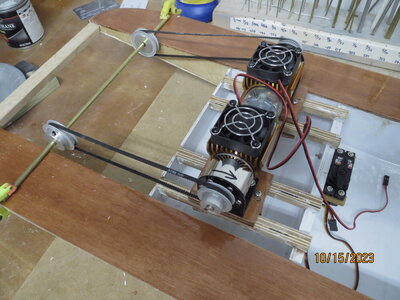
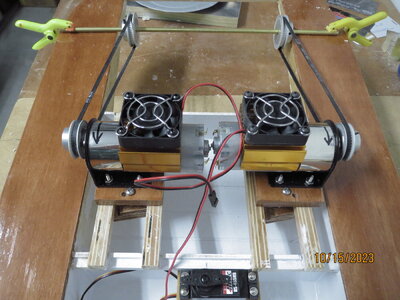
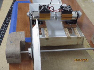
Fred, why a 3/4 " belt? They are incredibly strong. Or at least the toothed belts that I use. The Dumas toothless belts are not what I want. As I am going for 2 paddle wheels, and hence 2 motors and 2 belts, I am going to a much less massive arrangement.

IMG_8541.JPG
 
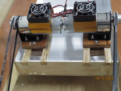
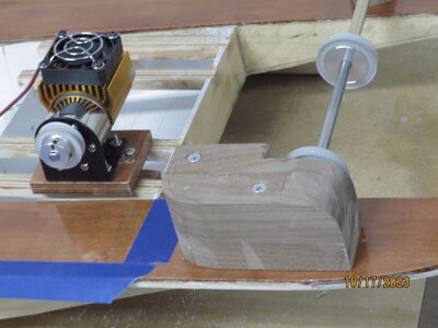
I also don't care for an extremely long belt, so I am moving the motors(on sledges for fine adjustment) to the next 'bay'.

IMG_8538.JPG
 
Sorry, I am wrong about there not being room for the pulley. I thought the axle of the wheel was down on the "jig" extensions, but your picture shows it is above that, so the extra width of my pulley shouldn't be a problem then. I need to get used to looking at BOTH, the side view AND the top view of the plans.
Although, I won't be using a 3/4" belt, probably 4 or 6mm. It's the pulley that is 3/4" wide. It includes the flange for the set screw.
 
As the pulley on the paddle wheel will be above the deck height and the paddle wheel bearing can be manipulated a bit, I think the paddle widths will be about as expected. Also I will have to have a slight gap between them as they might be going at different speeds. I had originally hoped to use the paddles in ' tank mode', that is using different (relative) speeds to steer, without needing a rudder. But these paddles are so close, unlike paddle boats with paddles on either side of the hull, that I think I will need rudders after all. Especially as Dumas found it necessary to ad little fins under the hull. When the model is on a flat surface, the only contact will be the very front of the hull and the rudders at back ! ! ! Dangerous ! So I may add a couple of side keels under the hull in line with the outer rudders. This should protect the rudders, and help with controlling the model. I wish I had thought of this before epoxying the hull. It would have been stronger than the 'add ons' I will now have to add. As the rudders are not too deep, maybe these 'keels' won't be too big.

IMG_8539.JPG
 
Sorry, I am wrong about there not being room for the pulley. I thought the axle of the wheel was down on the "jig" extensions, but your picture shows it is above that, so the extra width of my pulley shouldn't be a problem then. I need to get used to looking at BOTH, the side view AND the top view of the plans.
Although, I won't be using a 3/4" belt, probably 4 or 6mm. It's the pulley that is 3/4" wide. It includes the flange for the set screw.
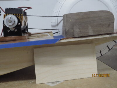
Yes, and as my motor mounting are on moveable' sledges', they will be quite high. Hopefully this will mean the belts rise towards the motors, minimizing the amount of water they drag into the boat via the little slots.
 
I like that idea of adding keels to protect the rudders. I have been doing quite a bit of reading on the PADDLEDUCK forum. Some people talk about putting a rudder near the front instead of the turning fin. I think I will reinforce my hull so that I can add any of these options at a later time.

I have tried to register at PADDLEDUCK so I can search for more ideas there. Unfortunately, they will not respond to my request to become registered. Do you use that site?
 
I know I am re-thinking this a bit much, but it occurred to me... my CQ will have about 1/2" of freeboard added vertically to the bulkheads and hull sides. This will raise the boat and paddle wheel also. To keep the wheel at the correct level in the water I have decided to go with small, 20-tooth pulleys. A 6mm belt will have more surface wrapped around those smaller pulleys to prevent slipping. Then, if necessary, I can mount the wheel a bit lower and closer to the deck. I'm also looking at a longer belt (586mm) to move the motor forward. The idea here is to move weight towards the bow. The longer belt will also give some space behind the motor to make a "belt wiper" for removing water.
Any advice, suggestions, ridicule, etc. is welcome.
 
Lots of good points there, maybe I should go over my calculations again. As you say, a smaller paddle wheel pulley would get the wheel lower. Must check!
 
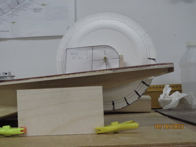
I just checked, and there is no problem. Truth is, deepening the hull has no effect on paddle wheel depth ! ! ! As long as free-board remains the same, deepening the hull only changes things under the water, not the paddle depth ! Of course, if you want to increase the free-board, then you will indeed raise the paddle blades. But from my quick test (below), it seems like the paddles will go easily below water level. Maybe even too deep. The water only needs to cover the blades. I've drawn them in black, and they are well below the water level (the top of the board at left of picture). So even raising free-board by 1/2 inch you should be OK. I hope this makes sense.

IMG_8542.JPG
 
Thanks for the testing. That makes me feel better. With the smaller pulleys, I will still have some up/down adjustment of the wheel height... just in case it's needed. Before starting the building, I want to get the major parts on order from China because shipping could take 3-8 weeks. When the hull is near completion, I will estimate the remaining weight and do a float test. That's when I can determine the actual amount of immersion of the wheel and position it accordingly.

This scratch building is much more fun than just following assembly from instructions. It exercises the mind.
 
Determining the amount of ballast is usually the last thing I think about. I assume that I will always have enough ballast on hand, or bigger batteries. I usually float the nearly finished model in the bath and add ballast as and where needed. The paddle wheel height is set with respect to the expected free-board, which eliminates one more variable!
 
just made the motor boxes, too heavy! used solid wood - I think I will eventually replace them with hollow versions. But these come apart - top and bottom halves- so extracting the paddle assembly will be easy.

IMG_8551.JPG

IMG_8559.JPG

IMG_8560.JPG
 
That's too bad because they look really good. It looks like solid walnut.

I'm in the process of figuring out the scaling factor of each group of parts that make up the hull.
It' s going to take quite a bit of trial and error (mostly error, I think). I'm going to use a program that enlarges, and then tiles an image into multiple pages. The pages can then be printed on 8.5x11 sheets and taped together.
 
Yes, some of those angles were a nightmare. If it turns out the paddles are too deep, I can slip a thin layer between the motor boxes and the deck. At the moment the toothed paddle pulleys JUST clear the tops of the deck covering the jigs. Phew ! The belt looks like it happily slopes up to the (model) drive motors, and my guess for belt length looks acceptable.
 
Hi Fred,
What drawing program (CAD) did you get with your machine? All I can find are just too comprehensive and complex instead of simple cut-out shapes. I know you are not starting on this part yet, just wondered what CAD software you got with machine
 
For the CNC machine I think I will be starting off using Easel. AutoCAD is too complicated for me. In Easel, all designing is done online so you don't download any software. It also sends the G-code directly to the machine, so no other software is required. Although, the machine will need GRBL firmware so it can understand the G-code. Maybe that's already on your machine? I looked at the following video to get an idea of what was involved with Easel.

 
For the CNC machine I think I will be starting off using Easel. AutoCAD is too complicated for me. In Easel, all designing is done online so you don't download any software. It also sends the G-code directly to the machine, so no other software is required. Although, the machine will need GRBL firmware so it can understand the G-code. Maybe that's already on your machine? I looked at the following video to get an idea of what was involved with Easel.

I have been trying to use Easel, with some success. The -CAM part, as you say, is great as it goes directly without messing with G-codes. However the CAD- part is not very flexible. For the paddle wheels, it would be much nicer if you could work in R-theta rather than always in X-Y coordinates. I just use a calculator and get the exact 'cos' and 'sin' values to position the 'spokes' etc. It only has to be done once on this model, so no big deal, I guess. But it is slow going! I haven't actually cut wood yet, just 'air cuts' but things are looking good.
 
I'm glad you had some success with the CNC process. I hope to try mine later this week. I don't know anything about R-theta or working with COS/SIN. For the wheel, I've ordered some styrene rods and will try gluing them up.

So far, my progress on the hull has been creating full size templates of the frames, etc. I have realized it will be a lot of work to increase the freeboard, so I'll build the hull per plan. Before putting on the main deck, I will investigate adding a 1/2 inch of freeboard between the top of the frames and the main deck. It'll be a slow process.
 
Back
Top