Scratchbuild Creole Queen

  • Thread starter Thread starter Ferd
  • Start date Start date
  • Watchers Watchers 3
I tried my CNC for the first time. It cut the sample file perfectly, but when I used Easel to design a simple .jpg file, it cut in the wrong position and also a little too deep. So, I am now looking into the g-code to see why. I think I just need to enter the proper g-codes at the beginning of the files. It'll take some more practice to get it right.

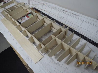
For the hull, I have all my plywood, and I am ready to start cutting the jigs and keel and gluing them up. After that, I intend to use my paper frame templates before cutting them, to first make sure the notches line up. Slow progress... but it was supposed to be a winter project and it's not winter yet.

How is your wheel design coming along?
 
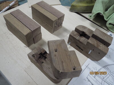
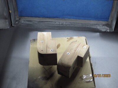
I've got the wheel layout as hoped for, in Vectric. Very nice free program, and much more flexible. However, I still have not converted it to -CAM, although things might change after this weekend. I have remade the motor houses, again in walnut as it really cuts well to hold the bearing. Unfortunately, once the parts are glued together, the bearing 'hole' can't be enlarged. When they arrived the bearings were slightly larger than that my slots, hence required rebuild. Just have to live with their extra weight. Keeping track of which part was top or left half ( and which set was port) took a lot of concentration! Measure 5 times, cut once ?

IMG_8572.JPG

IMG_8576.JPG
 
Paul, that walnut grain looks too nice to be painted.

Having made a few more engravings with my CNC, it's not as scary as I thought it would be. I've ordered various bits so that I can try cutting 1/8th inch plywood.
And I'm getting enough hull pieces made to know the scaling is working out ok. Nothing is glued yet, as some slots will need deepening and cleaning up.

As for adding freeboard, I decided it would be too complicated for me. I will follow you by sealing the main deck walls to the main deck.
I'm also thinking of filling at least some of the hull cavities with foam blocks. In case of capsizing, that may keep the electronics dry.

After glueing up the hull components, the jig extensions will need to be cut off - looks like a lot of work. What tool did you use for that?
 
Hi Fred, you are having more success than I am. I am using cut2Ddesktop to start the drawings, and then exporting to easel to communicate with the machine. What are you using? I really have had no success only a few ruined boards. How did you get the outlines? Did you copy from Dumas sheets, or draw them again from scratch? I'm getting very frustrated with this project !
Paul
 
I did not cut the hull pieces with the CNC - they were all done by bandsaw. I first scanned in the Dumas sheet to get a .jpg image. This was changed to a PDF file. ADOBE READER was then used to expand it to 404% size, and I tiled it into about 20 pages. These pages were taped together to get the full-size templates of the pieces for a 48" long boat. The templates were then cut out and traced onto 1/8" plywood and cut with my bandsaw.

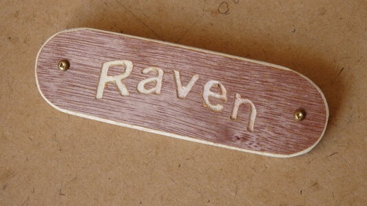
I did, however, use my CNC to engrave the nameplate for a sailboat that I built. The name of that boat is "Raven". The Raven letters were not typed using Easel; it was typed in MS WORD, then I took a picture of it and imported the .jpg file into Easel. Within Easel, I used IMAGE TRACE to make it a valid .nc file. From there I just filled in the bit and cut properties. The .nc file was opened in NC VIEWER (a nice handy free program). Here, I could see how the CNC would step through each line of the g-codes. The .nc file was copied onto an SD card in my off-line CNC controller and engraved.

Nameplate.JPG
 
Paul, that walnut grain looks too nice to be painted.

Having made a few more engravings with my CNC, it's not as scary as I thought it would be. I've ordered various bits so that I can try cutting 1/8th inch plywood.
And I'm getting enough hull pieces made to know the scaling is working out ok. Nothing is glued yet, as some slots will need deepening and cleaning up.

As for adding freeboard, I decided it would be too complicated for me. I will follow you by sealing the main deck walls to the main deck.
I'm also thinking of filling at least some of the hull cavities with foam blocks. In case of capsizing, that may keep the electronics dry.

After glueing up the hull components, the jig extensions will need to be cut off - looks like a lot of work. What tool did you use for that?
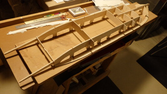
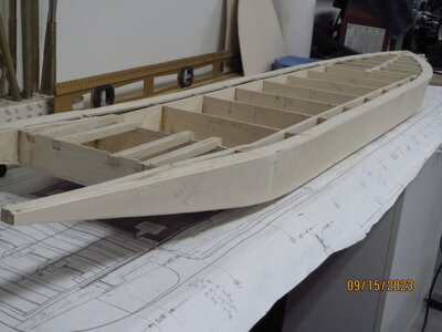
I thought it would be a lot of work, and a waste of wood. So I started building up-side-down with extra mini-jigs( for battery supports) to get everything aligned . Then turned it over to add main jigs (with no extensions.) Jigs are parallel sided except for rear part, which I interleafed with 3 thicknesses of ply for the paddle wheel support part (which I reshaped to avoid that odd curve around bulkhead 14). No jig extensions to be cut off ! The battery supports reached far enough forwards to lock into the front part (bulkheads 1 to 6). I added an extra bulkhead between 6 and 7, double thickness to be extra safe.

IMG_8497.JPG

IMG_8517.JPG
 
Last edited:
OK. That does make sense. I have just glued up the jigs and front keel. Tomorrow, I will glue them onto the working board, but I'm just going to tack them on. I'll figure out a way to cut all those extensions off - maybe just a hand saw and then use the belt sander to smooth off the top surface.

You mentioned "ruined boards". What exact problems did you encounter?
I somehow set depth of cut too low so the 'machine' cut too deeply, right into the spoil board. Also the 'offset' that I used must have been set wrongly because the finished wheel frame was too skinny. It must have been cutting on the vectors, rather than outside or inside them.

IMG_8577.JPG
 
I somehow set depth of cut too low so the 'machine' cut too deeply, right into the spoil board. Also the 'offset' that I used must have been set wrongly because the finished wheel frame was too skinny. It must have been cutting ON the vectors, rather than outside or inside them. In the pic here the tool is a point that just cuts into the work, and is ON the line. So when I replaced it with the 1/16 end mill, it cut everywhere 1/32 too narrow! Why it didn't offset it, i don't know, I'm sure I set it up to do so.

IMG_8577.JPG
 
Last edited:
My first engraving was also twice as deep as I wanted, and I never figured out why. I was using a "zero-Z" attachement and after that I switched to just zeroing Z with paper. That somehow fixed my depth problem and I found it quicker to do than use the zero attachment.

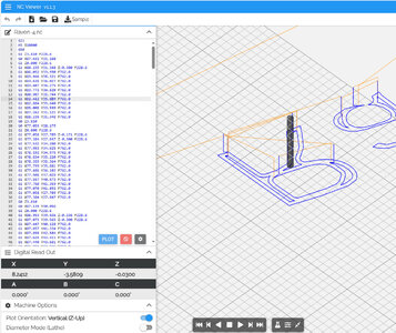
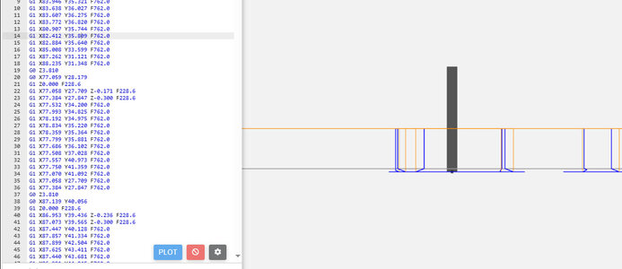
I have not used Vectric, but I found "NC Viewer" gives a much better simulation than Easel. Below are a couple of screen shots. You can step through the program one g-code at a time and, at the bottom left, it shows exactly how deep the bit goes ("Digital Readout" of X, Y, Z). The 2nd picture shows a side view. And this is done before any cutting. There is probably even better simulation software but this one is free and I found it helpful just for checking depth of cut.

Instead of engraving wood, my next step will be cutting plastic (styrene) all the way through. What material are you using for the wheel spokes?

viewer1.jpg

viewer2.jpg
 
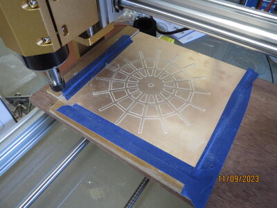
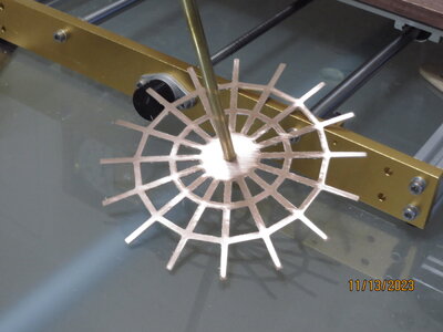
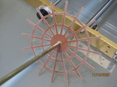
I finally got a piece cut out today ! Not perfect, but getting close. I am using copper/phenolic printed circuit boards, in the hope that I can solder the actual paddle boards onto the wheels for extra strength. But the copper does not cut cleanly (usual problem with pcb material) and cleaning up the edges is a real chore. I don't want to do it for every wheel before gluing them together in pairs (as Dumas). I may yet resort to using wood, unless I get better results with the phenolic turned over (copper on bottom)

IMG_8579.JPG

IMG_8580.JPG
 
Your wheels look great. How long did it take the CNC machine to cut one of those?

I'm playing a bit more with my CNC by trying different bits in plywood; straight cut, two-flutes seems to work well. So far I have not tried the wheel.
I'm now applying the bottom and sides to the hull, so it will soon be cut off the building board.
I found 1/8" birch plywood didn't want to bend at the ends of the boat so I cut those pieces across the grain and it worked much better.
At the bow I used balsa for the 3 planks and had to soak them to twist them into shape; also using balsa for the blocks at the very front.
To keep the balsa from being dented, I may cover it with resin & cloth.
 
Actually the wheels were a failure! The outside cuts and inside cuts had a problem. To get the outside cut outside the vector line, and the inside cuts on the inside of the vector sounds easy. But the prog. seems to want all to be one or the other. But I separated them into 2 files, and that worked. However the vectors are NOT zero thickness, so outside cuts go just a bit too far outside the vector. And similarly inside cuts are too far inside. Its not much - maybe .020 inch -but a tongue-and-groove pair would not quite fit by this amount. I overcome this be telling the prog. that I will be using a tool .020 smaller diam, so it moves the tool path enough to compensate for my original tool. As long as I remember to enter .042 " tool diameter, and use a 1/16 " tool ( .062 inch) all is well. There must be something I am doing wrong to need to do this? But what? Any suggestions appreciated.

IMG_8589.JPG

IMG_8590.JPG
 
Sorry, Paul, I don't think I would be any help. It seems you are way more advanced in running the CNC than I am.
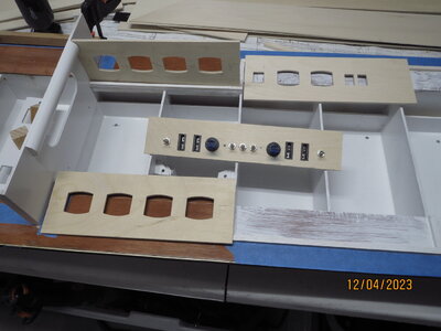
If those windows were done by CNC, they look very good.
I have started using Inkscape for design but it has quite a steep learning curve.
Inkscape has much more control over the nodes on a path than Easel.
I'm just getting started with all this and it's going to be a long journey.
Fred
 
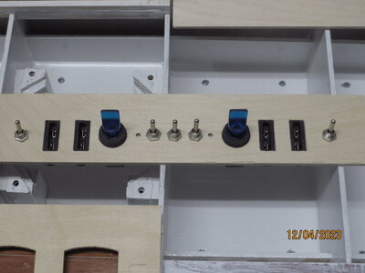
Yes the windows were all done on the CNC. I've now got most of the walls done for main deck and boiler deck. They have to be fully finished and painted before finally gluing them in, which means a lot of thought about the pillars and railings. Already the hull weighs about 11 pounds, so I am getting a bit apprehensive about final weight. It won't need much power at the expected speed, so I can use smaller batteries, but as they are low down, it won't help with stability. I'll just wing it, and test in the bath once most of superstructure is made. Vectric plus easel is really an easy combination once you realize a few ground rules. So far all I have learned is what I need - but that's enough for me - I have no love of computing beyond that.
 
With the weight at the bottom and light material for decks and walls it should be more stable. My hull is all 1/8" plywood (probably overkill), but my decks and walls will be much lighter. My decks will be 3/32" ply or 1/16" ply. The walls will be 1/16" styrene, 1/16" ply, 3/32" balsa or possibly even 1/8" model plane foam. I hope to have the hull and main deck done by Xmas and then I'll weigh it. Also, I may leave some windows open to let air through, a little less leaning in windy conditions!
 
I've previously built Battleships, and I usually build the same way - serious over strength! I'll be using 1/8' ply until I run out, then lighter solid (3/32'?) But by the time you add strengthening strips all round the edges to prevent warping, etc. who knows? I like being able to cut all walls out on CNC, it makes life so easy - not sure how you will do it with foam. Styrene expands horribly in strong sunshine and buckles like crazy unless strongly supported.
 
Thanks for the heads up on styrene. I've never used it before. Foam would also need support, so maybe I better stick to thin wood then.
Yes, I definitely want to cut the windows with CNC. They look easy to design & cut out.
I cut the hull off the building board today, but I still have to add the sides. I figured that would be much easier to clamp with the boat upright.
 
Styrene Paddlewheel Build Log

I’m building a stern drive paddle boat (Creole Queen) and could not find much information on building the paddle wheel. My experience in working with a CNC router and with styrene is very limited. So, I decided to do a build log of how I created the wheel from scratch. My choice of materials will suit my model but you may need to make adjustments to sizes and quantities. This build log will consist of several posts as follows.

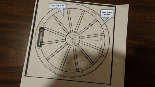
Make or find online a picture of a spoked wheel with the number of spokes that you require. Print it so that it is at least the diameter of your paddlewheel or larger. Only the spoke angles will be used by this picture. On the print, use a compass to draw a circle representing the outer extent of your spokes. Also draw the outer circle of a rim (or two) and the circumference of the hub.

Wheel Picture.JPG
 
Back
Top