Finally have all of the LH spark plug wires - inboard, outboard and magneto - in place. Small space to work in, lots of bending, lots of CA; finished, but as you can tell from the pictures, definitely not the job of an Aircraft Engine Mechanic 1st Class. Hope I have enough wire to complete the RH side (time to look in the left over stash from prior kits).
While taking a break from the model work earlier this week I took the time to do some research. There is not a whole lot out there but I did finally manage to locate some photos of the rear an engine that is (or was) on display in the Science Museum London, UK as well as some pictures of a cutaway engine (circa early 1920s) from a museum in Victoria, Australia. There is also a plastic model of the engine that I found (not sure if it is still available) and a 3D blog site with information on this model, a larger version built under license by Wright-Martin, and the Clerget 9B engine. The basic information on the engine is available on Wikipedia and a couple of other sites. One interesting item turned up is that many of this engine model, and the larger Wright-Martin version, were converted in the 1920s to coil ignition by a firm in Minnesota and used in racing boats.
Websites:
Posts about Hispano-Suiza written by MBIQModels

mbiqmodels.com
(the larger Martin version is at
https://mbiqmodels.com/engines/hispano-suiza-8f-scratch-built-18/ ; the Clerget 9B can be found under the Engine tab at the top of the blog site)
Intodution of SE5a with Viper-engine Aircraft
theaerodrome.com

www.hobbysta.eu
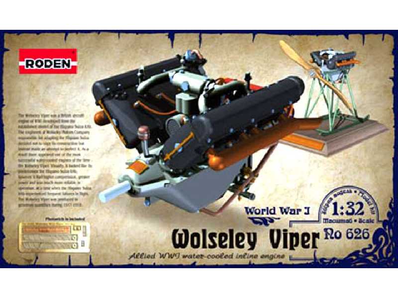
The Wolseley Viper (Hispano-Suiza W.4.A*) aero engine is a V8 cast block design produced under licence from Hispano-Suiza by Wolseley Motors Ltd, Birmingham in the United Kingdom during the First World War. This example is fitted with a Zenith carburettor and carries the serial no. 2339/2275 and...

collections.museumsvictoria.com.au

en.wikipedia.org
Aircraft Manuals Helicopter Manuals Propeler Manuals Flight Manual Illustrated Parts Catalog

www.aircraft-reports.com
https://collections.museumsvictoria.com.au/items/399884 (digging into the website, it seems that the engine is in storage and not on display)
****** PICTURES ******
Top view, LH inboard ignition wires

Ignition wires installed at LH magneto


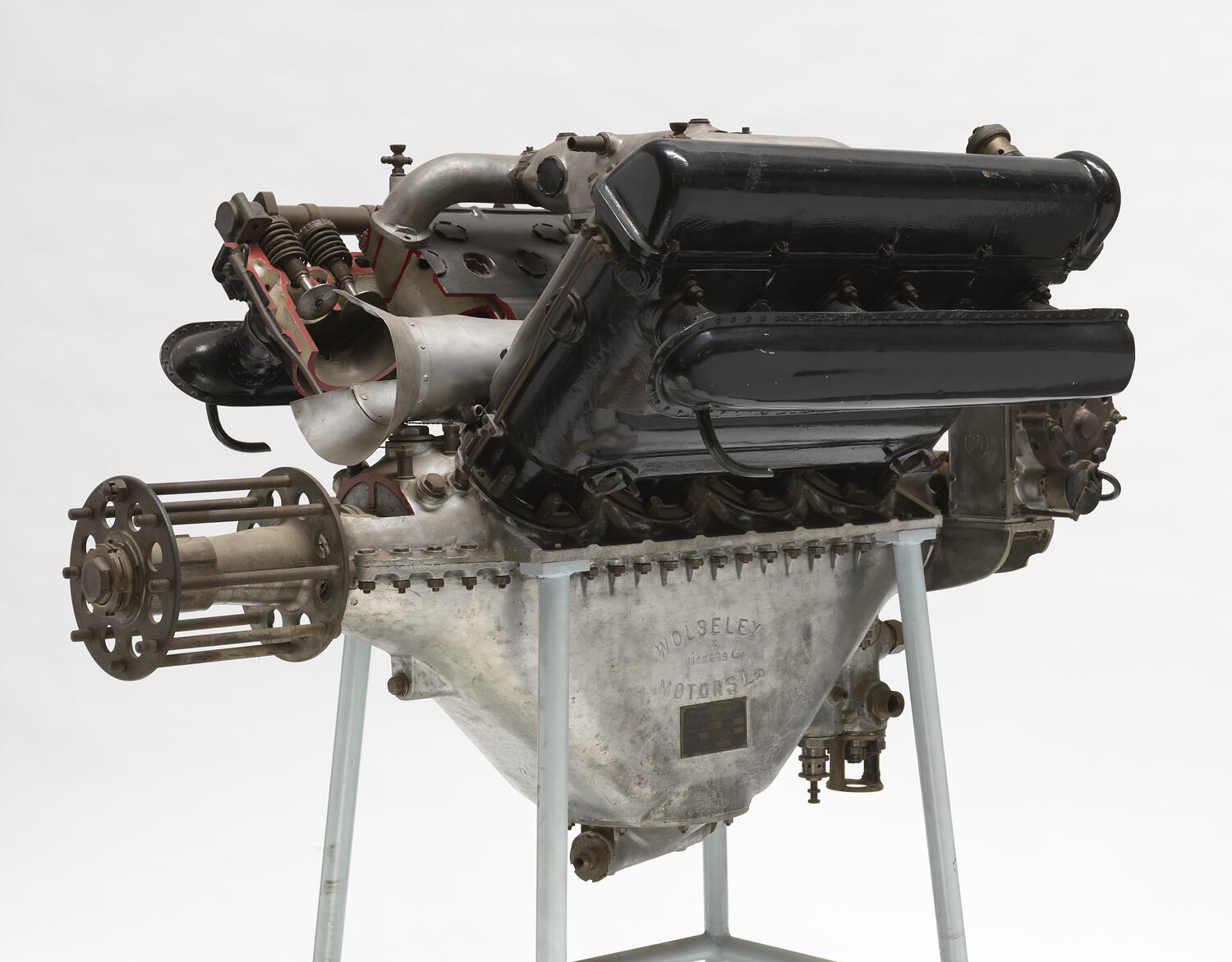
Engine in Science Museum London, UK
.jpg")
Engine on display, Museums Victoria, Australia
.jpg")
.jpg")
.jpg")
.jpg")
.jpg")
.jpg")