Signet's Bonhomme Richard Cross Section [COMPLETED BUILD]

Hi Signet,

I follow you now and then because I want to build this kit in the future.

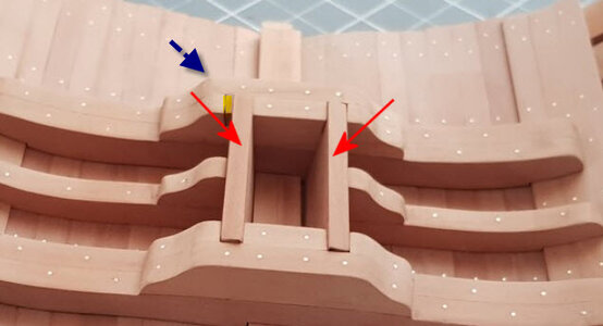
Is this the block I made yellow for the blue arrow?

I see at Uwek's post #102 there I also see this block (I think)


Regards

Henk
blokje.jpg
 
Hi Signet,

I follow you now and then because I want to build this kit in the future.

Is this the block I made yellow for the blue arrow?

I see at Uwek's post #102 there I also see this block (I think)


Regards

Henk
View attachment 281941
No, I'm asking about the larger pieces that the red arrows attach to. I actually only see the small area in yellow on Stan's build, and assumed it was a small error, which will be covered up later anyhow. Ewek's post, and other posts I've checked, don't have the small filler you've shown in yellow.

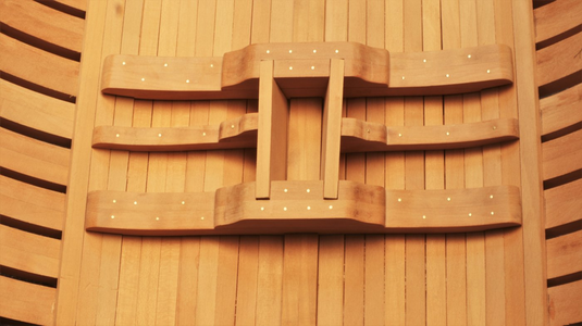
Ewek's post shows this before installation of the parts in question:
1641913465481.png
And afterwards with the parts installed:
1641913493540.png

I have all the other parts, only the information on the ones previously identified with red arrows fail me.
 
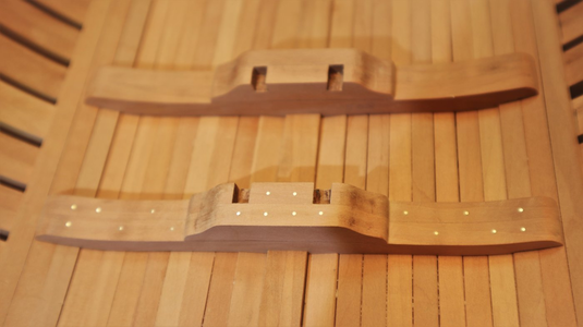
Signet, on 7 Sep 2019, Uwe did a kit review and posted it on this site. In his post#3 there are a lot of photos of what is supplied in the kit. In the 21st photo, in the upper right section of the photo, I think you will see the parts you are talking about. I went back through my stuff and have the same shaped 1512 parts, not the right shape. Unfortunately I tossed my parts list after I completed my kit so I can't be more specific. Hope this helps.
 
Signet, on 7 Sep 2019, Uwe did a kit review and posted it on this site. In his post#3 there are a lot of photos of what is supplied in the kit. In the 21st photo, in the upper right section of the photo, I think you will see the parts you are talking about. I went back through my stuff and have the same shaped 1512 parts, not the right shape. Unfortunately I tossed my parts list after I completed my kit so I can't be more specific. Hope this helps.
Bless you sir! For you great eye! (Or maybe 2) That is IT. And better yet, I have it. It was with the packet of optional interior wood, as it was grouped with Ewe's review, and it is shown nowhere in the main instruction manuals diagrams and description of each board included! And the optional interior doesn't have such a diagram.

1641955841647.png

I had intentionally set that packet aside, and after checking all the ones supposedly included with the basic kit, never even looked there. Those little suckers even popped right out, anxious to be included! :)
 
Hi Signet,

I follow you now and then because I want to build this kit in the future.

Is this the block I made yellow for the blue arrow?

I see at Uwek's post #102 there I also see this block (I think)


Regards

Henk
View attachment 281941
I think I know what the yellow block is: the two parts at either end that the "missing" parts fits into are not cut the same, but are off a bit. They can be made to fit, but will not end up quite parallel. Or one or more notches can be widened, with the extra width filled (with glue, filler or an extra piece, I think as shown above). In fact, I think Ewe's photo shows them not quite parallel, which at the bottom of the well, may be the least visible solution.
 
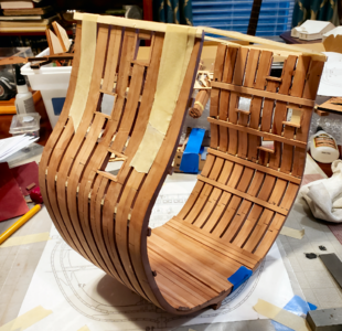
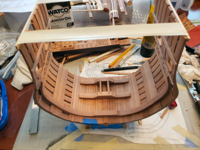
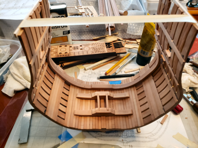
My progress so far (other than making the later-used mast step parts and doing lots of research):
20220112_212505.jpg
I'm not proud of it. I made many mistakes. But sometimes mistakes can help others more than perfection. I fear my build log will be a constant list of how-not-to's rather than how-to's, but if it can help others, and if I'm happy in the end, I can live with that.

Here are some points, or maybe cautions, which I found that might help others:

(This is my first real plank on frame model - my last too I'm sure - so I'm sure those already building such models already know most if not all of these.)
  1. The first 6 frames of this model are essentially identical, so one would be advised to use the plan's cross section drawing and try to build them as accurately as possible. I did try that, but didn't concentrate enough on it, thinking I could sand it all to match later.
  2. Even frames 7-9 can be laid out on the same plan cross section, although they won't match at the mid-bottom area. But will at the keel and top.
  3. Don't worry about exact location of the sides of the frames at the top; when assembled, they're springy and can easily be moved a half inch or so. But when at, or placed at, the right width, the profiles should match.
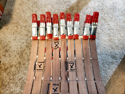
  4. Alignment of the 7 ribs to make up each frame is very important. I tried some overlaying the plan, others built up as they most easily assembled, still others over top of their mating frame. I tried many methods of clamping, and can't say I've found the right one. Thank goodness I'm done with them.
  5. My assumption that "everything can be sanded" caused problems. And using too many clamps hides the joints and "flushness" of one part with another. Many was the time that after removing the clamps, I discovered that something wasn't in good alignment at all. I found that when clamping the tapered joints, the pieces tended to separate. While clamping is great, and highly recommended, I think I'd have done better just gluing and placing the pieces over the plan (covered with wax paper) and leave them there, instead of getting high on clamping and weighting.
  6. When one rib is not quite flat against the work surface while others are, it's fixed by sanding. The rib is now to thin fore-to-aft. When one frame is not properly aligned over its mating frame, it's fixed by sanding. The frame is now too thin in vertical/side cross section. When one frame is not the same profile as it's neighbor, it's fixed by sanding. Both frames are now too thin in cross section.
  7. Alignment. I seem to be using that word a lot. And I didn't think my work was awful. But it was. Due to poor alignment. Everywhere. And problems due to that continue.
  8. The height of my frames varied a fair amount. You know why. I then trimmed them down to make them the same before fitting to the jig. But missed one. They're still a different height after assembly. I'm not worried about the overall height, because the top of the frames get lowered more yet. But probably I should be worried, because everything else I didn't worry about came back to haunt me.
  9. I clamped mating frames together and tried to sand them to match better BEFORE putting them into the jig and assembling them. I used power sanders. Saved time. Results - not so great.
  10. The assembly of the frames into the jig didn't go badly at first. Put all the stringers in place. Wished those were solid wood, though, instead of plywood; they tended to separate if clipped. I installed them smaller thickness horizontal so as to enter the slots at either end. I THINK that was correct, and think they formed stronger spacers that way.
  11. I had problem, however, gluing the spacers to the frames. While the frames appeared spaced pretty well, there was space between them and the spacers, sometimes on one side, sometimes on both. I had intended to super-glue them in place, but they weren't close enough to glue, even using Titebond Instant Bond Gel. So, I clamped at the bottom, from one end of the section to the other, on both sides, closing up those gaps, and glued. Stupid me didn't consider that all those gaps would be removed, so my section is now 1/8" shorter at the top deck area than at the properly spaced keel. I'm not correcting that at this point; I'm hoping it won't matter (I'll center all rips and details). But then there's always sanding.
  12. I found that even clamped, the super glue didn't hold that well, mostly because only the bottom spacers were tight. So I used Titebond Quick and Thick to fill in areas above and below the spacers, to make for a secure connection. Of course, those areas required a lot more sanding later.
  13. I removed the assembly from the jig for final sanding. Well, for all the rest of the sanding, starting with 60 grit on up. Everything getting thinner at that point, but it's pretty even. Using power at first, finishing with all by hand, I sanded everything up to 150 grit, and the areas I think will be visible to 320 grit. Surprise - frames got thinner after sanding.
  14. I was tempted to leave the top set of spacers in place, to keep everything spaced right, but in the end took them out too, for easier sanding, and hopefully allow the frame assembly to move to accommodate decking cross members.
  15. I didn't take Ewe's excellent advice of leaving the keel off, for fear of damage during sanding, during the above procedure. I was SOOO careful, then at the very end sanded off the bottom part at and angle at one end. No problem - I'd been thinking of sanding the whole keel down a bit and adding a keelson, which I think should be there anyhow. ;-)
General appearance is okay, and will hopefully get better as more is added, but the words "perfect", "excellent" and "quality" never entered my mind, as it always done when viewing the work of others here.

I hope this doesn't put all you readers off of following this thread. I truly do have some ideas I think may be of general interest, and hope it all doesn't end up in a diary of what I did wrong.

I think I get to do some planking soon, but I'm going to go back and fine-tune my modified method for locating decks and gun ports first. They have to be ALIGNED right, after all.
 
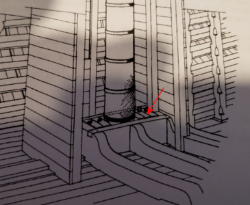
Thinking ahead, and since I have all the rest of the mast step pieces prepped, I have a question about the "wedges" used on the fore and aft sides of the mast to hold it tightly on the mast step. The desired arrangement is something like on a 74:

1642048852490.png
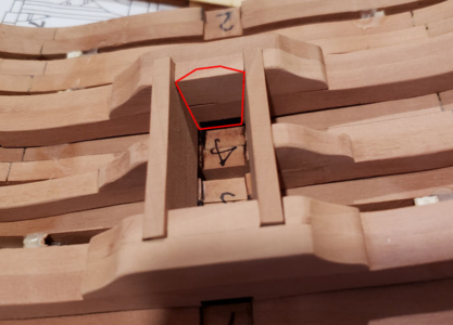
They usually have eyes for lifting, and I think I've seen them with rounded tops. As they fit between the two slanted side supports, I would think they would be basically trapezoidal in shape, except would have sufficient side clearance to drop further to be tight. They fit in the mast step more or less where outlined in red:
1642049017807.png
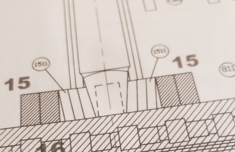
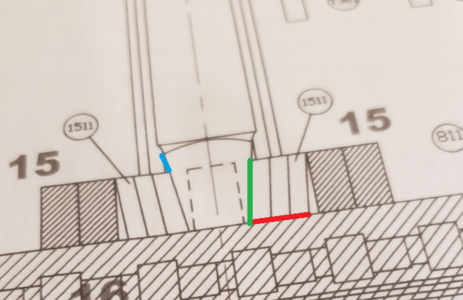
As shown in a previous copy of the model plan's cross-section, these are denoted as parts 1511:
1642049085166.png
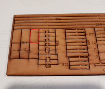
However, the parts included in the kit are simply rectangular, and are not wide enough to make a properly fitting trapezoidal form:
1642049137449.png

So, should these be used for this? Are they the right shape, or should they be scratch built? Also, on the plan section, SOMETHING has to wedge these pieces from the bottom in order to keep them tight against the tapered portion of the mast. Maybe a triangular section? Won't be seen, but the 1511 pieces will just fall vertically unless something forces the bottom against the mast.
 
So, should these be used for this? Are they the right shape, or should they be scratch built? Also, on the plan section, SOMETHING has to wedge these pieces from the bottom in order to keep them tight against the tapered portion of the mast. Maybe a triangular section? Won't be seen, but the 1511 pieces will just fall vertically unless something forces the bottom against the mast.
my fast 2 cents:
SOMETHING has to wedge these pieces
I guess there is nothing necessary - due to the fact, that these 6 wedges are tapered at the bottom (angle between red line and green line) - they will not move, if they get a horizontal force by the mast - otherwise they would lift up
1642049085166.png

Are they the right shape, or should they be scratch built?
The green line is showing the contact area of the mast foot - so the wedges would have the same form like the area in green - everything above (blue line) would be nice, but will not be able to take over forces, because there is no contact area

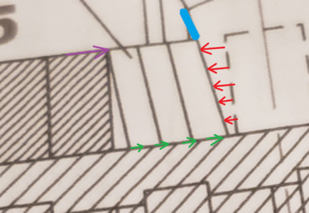
These are showing most of the forces at a mast foot

1642049085166a.png
Red arrows are the horizontal forces from the mast towards the mast foot
green are the friction forces pushing against
and also purple the forces of the frame agaiunst the wedges
 
my fast 2 cents:
SOMETHING has to wedge these pieces
I guess there is nothing necessary - due to the fact, that these 6 wedges are tapered at the bottom (angle between red line and green line) - they will not move, if they get a horizontal force by the mast - otherwise they would lift up
View attachment 282353

Are they the right shape, or should they be scratch built?
The green line is showing the contact area of the mast foot - so the wedges would have the same form like the area in green - everything above (blue line) would be nice, but will not be able to take over forces, because there is no contact area

These are showing most of the forces at a mast foot

View attachment 282354
Red arrows are the horizontal forces from the mast towards the mast foot
green are the friction forces pushing against
and also purple the forces of the frame agaiunst the wedges
I don't think it can work that way. Not that it's different, but let's look at the actual ship structure from the 74:
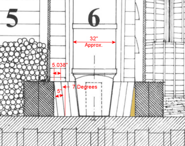
1642092990666.png
Before getting into measurements, note that the author has pretty specifically shown clearance between the top of the "wedges" (I'll call them) and the mast, but little or no clearance at the bottom. It would appear the horizontal force would only push at the bottom, were this the case.

To give us an idea of dimensions, I've scaled the main mast diameter at this point as about 32". I'm sure I'm wrong, but it's close and a variation one way or the other makes no difference to this discussion. Then the wedges scale about 5" thick. If there is no support triangular block (highlighted to the right), they are free to move. Also notice there is no clearance to the bottom of the wedges and the keel. I originally thought they would be tapered and forced in place, but once they bottom out, they can't produce any side force.

Anyhow, due to the angle of the wedges, the dimension at the top of the wedge is larger than 5" due to the angle. Over 1/32" larger. So any vibration or movement, of which there is plenty at sea, would tend to allow this block to move from and angle towards vertical, loosening the mast at the top, and allowing the other wedges to do the same.

What I think is happening here is that there are triangular shaped blocks behind these wedges, with the angle of the block being slightly greater than the angle of the mast taper. Inserting the wedges then provides a solid support, at the bottom of the mast, against longitudinal movement. They'd probably put in two wedges of a logical size, then make one of special size between the other two to keep the clearance down to a minimum or as tight as possible. This support at the bottom of the mast, the huge downward force on it, and the wedges surrounding the mast at its other connection to the orlop or gun deck, as the design may be, will securely hold the mast.

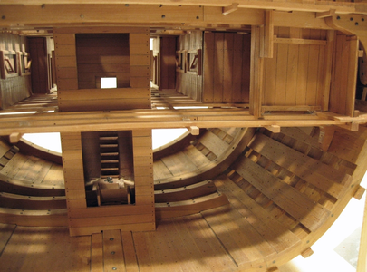
If that is all the case, while we can't see the triangular block on a finished model, it may be necessary to include such a block to keep the mast in place (although a pin in the center would do it too). The wedges themselves I would think would not actually have tapered bottoms or tops; they could have, but actually serve no purpose here. Forces are produced by physical elements, not friction. But to answer my original question, I would think they would be tapered to the sides, simply to fit and stay in place better than rectangular blocks would. That would tend to mean scratch built pieces. Jeronimo's incredible model tends to confirm this:

1642094117811.png
This also shows a way to provide a view of this area, although it appears mostly covered with barrels on the completed model.
 
Since I mentioned that I had trimmed the tops of my frames some, to try to equalize them as they weren't all the same length, I was unable to use the template provided in the manner described. All the heights would be wrong, because they assumed you were measuring in the jig from uncut frames. To be honest, I never liked that idea much, anyhow: any variation in frame height would change the location of all the decks, and I'd be surprised if many people didn't have variations there.

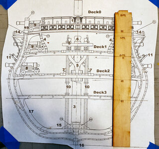
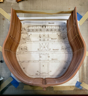
I feel it's more accurate, especially in my case, to measure from the keel up. The photo below shows the relationship between the cross section, the template, and the keel. Obviously the top of the template (now the bottom at the keel) is a measuring point:
20220113_130659.jpg

So, I felt pretty comfortable simply laying my completed frame assembly over the cross section plan, and marking the lines for the deck supports:
20220113_131718.jpg
The tape at the top was used to help keep the spacing at the top deck at the correct width.

I then marked all the deck level lines on the inside, and the gun template lines on the outside. I fudged a tiny bit on the horizontal location of the guns, so as to have the edge of an opening coincide with the edge of a frame. There is plenty of clearance for this, the appearance does not change perceptively, and only 2 frames must be cut for each opening rather than 3:
20220113_141616.jpg

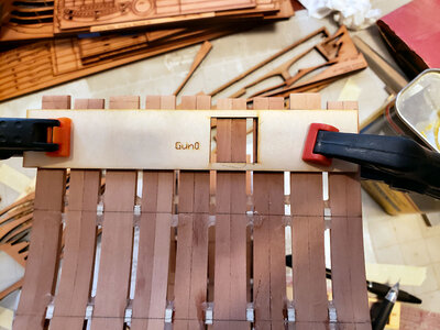
Before beginning to cut, I added a piece of scrap across the tops of the frames:
20220113_144806.jpg
Notice that the strip is glued ABOVE the line used to locate the Gun0 template, so it doesn't interfere with checking that template. The frames will eventually be cut at the top of the Gun0 port, so nothing gets in the way. After cutting, only frame 8 (2nd from the left) will only have one point of support, and while it will be adeguately strengthened once the top rail and planking is added, I may add a couple more spacers to keep in strong in the meantime.
 
I've just finished installing the top part of the keel and the 2mm planking to either side. I used the templates to locate the thick stuff location, but an even 8 planks ended up in the same location, so I decided to install this planking beforehand.
1642263647613.png
I also have the mast step placed in an approximate position, but it has yet to be fitted, and won't be until I put in the thick stuff.

BTW, lacking any specific information, I've gone with 1324 sequence planking in this area, and may do that throughout. Due to many cutouts and details, it's difficult to see too much open planking at one time, and with this also being a smaller ship, I didn't think something like the Victory's 13524 was appropriate.

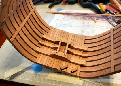
You may recall in the discussion above that parts identified for use in this area as # 1512 were not what was required, and we found the correct 1512s with the optional interior woodwork. That's fine, but I still do have the original 1512s, shown as the small parallelogram pieces laying below the mast step assembly. They appear to be at about the same angle as other pieces in this assembly, like they should be used there somewhere, but if so, I haven't found how. Did anyone use these pieces? If so, where.

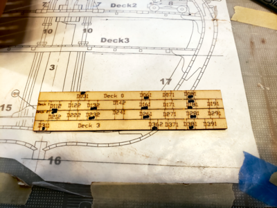
You may also notice above that there are more notches in the Deck3 (orlop deck) plank to hold the cross members on the left than on the right. I looking at the top view of the deck, as well as the crossmember cutting and placing template, it shows all cross members:
1642264189643.png
Well, as anyone who has built the kit knows, only about every other cross member is a thick, deep laser-cut piece; the rest are thin strips, and require no cutout in this board. To remind myself in the future, I marked up on the template those that DO need cut to fit.

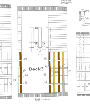
On that subject, the instructions aren't very clear to me and the diagrams a bit confusing:
1642264642447.png
The dark brown beams, D311, D362 and D381, are laser-cut main beams with cutouts for other structural members. The tan beams are apparently strips of wood, about 1x5 mm. I say apparently, because they all have part numbers (D371 and D391), but near as I can tell they are not laser-cut, but rather stripwood. Like the hull planking. That being the case, I REALLY wish - OMG - I just noticed the little note at the bottom of the diagram about those parts! Hadn't seen that before! Okay, that makes it clear - thanks.

But the point is, that since these are stripwood, and since they go ABOVE the previously mentioned cross beams, no cutout is necessary for them in the deck support planks. Which again, is why I marked the template as I did.

I'll probably put the thick stuff in next, but then before installing the mast step or going too far on the hull, may look at the interior detail kit in detail to find out what my affect this area.
 
Last edited:
Thick stuff has been added. I'm trying to decide what on the inside to plank between there and the orlop deck. Example builds show everything from no planks to all planks. Most of it does end up hidden, though.

1642459926923.png

Also went ahead and added the gun door with surrounds. After marking the doors, I drilled a 1/4" hole in the center, then used a coping saw to get close to the outlines, finally mostly used an X-acto blade to finish the opening. Once I got to checking the sides, I found all openings undersize. Guess they didn't figure I'd use a pencil inside the templates to mark them. So enlarged them.

I didn't install the surround parts per the drawings (shock - but in this time good). The drawings show the vertical pieces going the full height, while the horizontal pieces stop inside of them. Uwe's build documents the fact that on the original the lower sill extends to the inside, slightly inside of the inner hull planking. The other three sides are flush with the inside of the planking, so planking overlaps them. After trimming and gluing all surround parts in place, I used a narrow carving chisel to bring the sides and top flush with the frame, and let the sills extend out further.

I'm thinking I need to play around with some of the internal structure, cabins and such next, since it attaches to the orlop deck structural members, and all needs to fit the hold's structures. That and the mast step.
 
On the shot locker, it's supposed to hold the 3 sizes of shot on board. Should there be partitions, or separate levels or access points, or something to divide and provide access to them? I have asked also on Jeronimo's BR build site. He mentioned this and provided pictures on post 62 of this that thread.
 
In looking at the build order of this kit, it seems to me I have to consider lots of later parts, such as the royal pumps, before completing the hold, as they definitely affect it. So I'm trying to anticipate, and am now looking at the pumps. I have some questions...

Concerning the Royal Pumps:
The parts in the kit for the bodies of the pumps is 6mm material, which works out to 11.3" across flats, yet The 74 Volume 2 says the bodies should taper from 13" to 15.5", a good deal larger. Do you think the BR had smaller pumps, or is this just a kit simplification?

The Pump Well is a reinforced wood structure that goes from the orlop deck down to the keel and encloses all four main royal pumps and the main mast which they surround. What is it's purpose? The pumps do not move, near as I can tell, only the spear which actuates the piston. The crew connect a lever to the top to operate the pumps. The pump well never fills with water, of course. What is then the purpose of this pump well structure? It would seem that without it, somewhat more deck room and better access for pump maintenance would be provided. The well was apparently a really foul-smelling area (surprise!_, but would be less so without the enclosure. Does anyone know why the enclosure/well is there?

The description of how the pumps are primed and prepared for operation, and operated by means of an 11' lever with 14 lanyards attached for operation by 14 men to remove about 600 liters per minute of seawater is extensive, though no picture of the lever is included. Would there be a lever for each pump? If so, then could a lever be fitted to each pump, and 56 men be utilized? I can see where this would really help with a fair size leak, but with the complex startup procedure, and the fact that a wooden ship must leak somewhat all the time (plus water added from high seas and rain), wouldn't some bilge pump have to be used on a regular basis, and not require the startup procedure?

So, for all you 300-year-old sailors out there, how about enlightening me (us)? :cool:
 
wish - OMG - I just noticed the little note at the bottom of the diagram about those parts! Hadn't seen that before! Okay, that makes it clear - thanks.

But the point is, that since these are stripwood, and since they go ABOVE the previously mentioned cross beams, no cutout is necessary for them in the deck support planks. Which again, is why I marked the template as I did.

I'll probably put the thick stuff in next, but then before installing the mast step or going too far on the hull, may look at the interior detail kit in detail to find out what my affect this area.
It is taking some time to understand all these drawings and cross section, but with some time the modeler will understand the way, french shipwrights were constructing the beams, carlings and planking - different to the british way
You are on a good way
 
In looking at the build order of this kit, it seems to me I have to consider lots of later parts, such as the royal pumps, before completing the hold, as they definitely affect it. So I'm trying to anticipate, and am now looking at the pumps. I have some questions...

Concerning the Royal Pumps:
The parts in the kit for the bodies of the pumps is 6mm material, which works out to 11.3" across flats, yet The 74 Volume 2 says the bodies should taper from 13" to 15.5", a good deal larger. Do you think the BR had smaller pumps, or is this just a kit simplification?

The Pump Well is a reinforced wood structure that goes from the orlop deck down to the keel and encloses all four main royal pumps and the main mast which they surround. What is it's purpose? The pumps do not move, near as I can tell, only the spear which actuates the piston. The crew connect a lever to the top to operate the pumps. The pump well never fills with water, of course. What is then the purpose of this pump well structure? It would seem that without it, somewhat more deck room and better access for pump maintenance would be provided. The well was apparently a really foul-smelling area (surprise!_, but would be less so without the enclosure. Does anyone know why the enclosure/well is there?

The description of how the pumps are primed and prepared for operation, and operated by means of an 11' lever with 14 lanyards attached for operation by 14 men to remove about 600 liters per minute of seawater is extensive, though no picture of the lever is included. Would there be a lever for each pump? If so, then could a lever be fitted to each pump, and 56 men be utilized? I can see where this would really help with a fair size leak, but with the complex startup procedure, and the fact that a wooden ship must leak somewhat all the time (plus water added from high seas and rain), wouldn't some bilge pump have to be used on a regular basis, and not require the startup procedure?

So, for all you 300-year-old sailors out there, how about enlightening me (us)? :cool:
A principle hint:
When you ask a question or even questions it is helping the other modelers with 300 or less years of experience, if you would add a sketch, a copy of the drawing or photo of another model, so we can understand your questions much easier and more accurate.
f.e. I do not understand, why you write, that the pump well will be not full of water - because the well (what I have in mind) will be full of water
so therefore it is maybe because of a different definition, what you means with "pump well"? Therefore maybe a sketch where you show your "pump well"
Just a suggestion.....
 
Inside frame done (probably has a special name, I know). Some more planking within the hold done; I think I'll leave the rest open. Then plank the inside from the orlop deck up. With the inside frame and mast step just placed in place (wrong place in one position):

1642608058693.png
1642608075586.png

It is a bit confusing, as Uwe mentions above, to figure the order for stuff. The frame has to be located before working on the pump well and shot locker which needs to be in place before fixing the orlop deck, but it shouldn't be there for ease of planking at the orlop deck, etc.

I figure I can't go wrong with making up separate parts and playing with them, then mounting them as determined best. And it gives variety to the build.
 
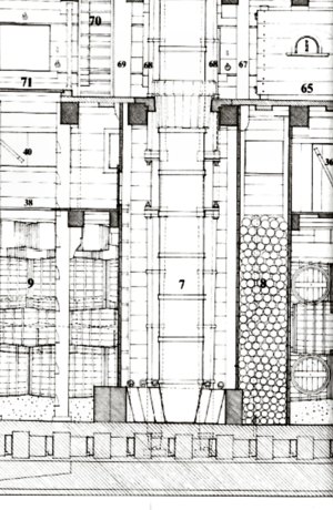
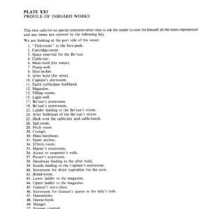
To clarify some of my questions concerning the Pump Well: As those familiar with the BH kit with optional inside structure and the construction of similar 74s, there are two structures, buildings, really, that go from the keel to the top of the lower gun deck, and are enclosed in the hold and on the orlop deck:
1642632863981.png1642632995476.png
Item 7 is the Pump Well, and item 8 the Shot Locker. Each are approximately 16' high and 8' wide, while the shot locker is about 5' long (longitudinal to the ship) and the pump well 6' long.

The Pump Well then is 5' x 8' x 16' high, spanning the hold and orlop deck, and encloses the main mast, the 4 royal (elm-wood) pumps and near the keel, most of the mast step. he pumps themselves are long double-cylindric-shaped apparatus the start either side of the keel, and end above the middle gun deck (Deck 1 on the model). The suction for the pumps lies just above the bottom hull outer planking:
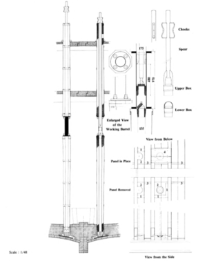
1642633662628.png

When the pumps are operated, water is brought up through them to the middle gun deck, where it is pushed out on deck and, hopefully, overboard. So that normal seepage into the ship will seek the low point, past the limber boards where bilge water normally accumulates.

This next part is an assumption by me: I feel that unless the ship has a major leak, that the water level at the bottom of the pumps will be lower than the planking of the hold (about the top of the keel). If water were to only partially fill the pump well, it would cover the mast step, contributing to rot etc. The Pump Wells, along with the royal pumps, were often added to ships, and were not a part of the original structure of many ships. Therefore, they would tend to be constructed basically as "rooms", as shown on the model and elsewhere. I would definitely NOT think these rooms, including the Pump Well, would be waterproof, and with sufficient leakage, tend to fill up this "well". The weight of water filling an 5' x 8' x 16' well would amount to 20 tons! Therefore, I don't think that under normal conditions the pump well would have any water in it to speak of, other than due to sloshing, rough seas, pump leakage, etc. If it started filling up, it would leak into adjacent areas, like the shot locker.

IF my assumption is true, then my question above follows: Why enclose it, limiting storage and access to the pumps, main mast, mast step, etc.?

It doesn't matter to the model; the structure is there and I'm going to model it. I was just curious about its purpose, and if others want to argue that as it's a well, it's normally half full with 10 tons of water or whatever, I'm not going to argue as I don't know the facts.

Perhaps I should just stick to the model, rather than the ship's operation, which is complex enough in itself. :-)

For those with less than 300 years of sailing experience, any thoughts on the pump size question above? Are they undersize because it was different than a standard 74, or because the model-designer didn't have wood thick enough, so it was simplified?
 
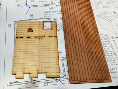
I'm trying to figure out the pump well and shot locker assemblies included with this kit. Those who have built the model recall, I'm sure, that thin ply walls are included with this kit, but they aren't actually meant to be included with the build (although they were used by some), but rather as templates to lay stripwood over bracing to form the structures. The photo below shows one of the templates and a sample of the stripwood (in this case actually laser cut in solid wood rather than actual strips):

1642654492875.png


I have two questions: First, the laser-cut stripwood is etched with the sizes of the separate "planks": 1x4 (mm), 1x2, 2x2, and lots of 1x4 and 2x4. In most cases, like the blue arrows above, no stripwood sizes are show. At the bottom, I find no parts identified as 20U, but they scale to 2x2 stripwood. At the top, part 20C refers to the template, of which there is only 1, not the wall built of stripwood, of which 2 are required. Again, no stripwood size is given, but it scales 1 mm thick, and as most are probably 4 mm wide. You can see that the horizontal wall with the second arrow above, which is numbered again with the template, must use thicker stripwood, probably 2mm thick. So, do I just pick laser-cut stripwood that matches the shown size approximately?

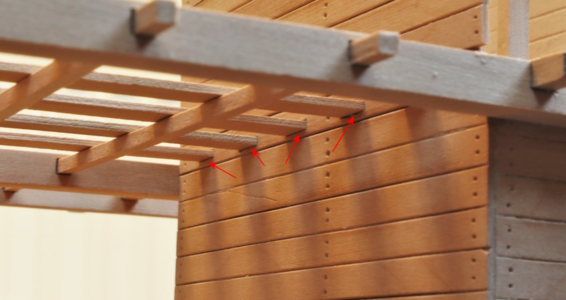
The second question is about the thin slots in the side wall template. The purpose of these is to allow the 1x5 deck supports to go through the outside wall of the structure and rest in the notch of the longitudinal stringers (there are 4 across). In that dark area of my mind, I swear I saw a laser-cut piece about 4mm wide that would basically be a single plank at this level with the laser-cut 1x5 holes included. But I can't find it. And if it exists, and is missing, I've lost an entire sheet. So my main question is: Did others building this model with the optional interior have laser 2 cut 4mm planks with these slots in them?

The best picture of these that I can find is on Uwe's build, with the slots identified with red arrows:
1642654602051.png

Can Uwe or anyone remember if the plank with these slots is simply an expertly-pierced cut stripwood plank, or if it is/was in fact a laser-cut piece with the slots already in? If the latter, I've got to find them somehow, as there are no doubt other parts missing. If they were made, then I'm simply going crazy, but have everything I need.
 
Back
Top