Signet's Bonhomme Richard Cross Section [COMPLETED BUILD]

BTW: I lke your new avatar very much - I think it is an Healey 3000, or? One of my favourite classics next to the Jag XK 140
It's a 1956 Austin Healey 100M, or LeMans Healey (only 640 made). I owned it back in the 60s, and had to sell it to help buy our first house. Sold it for $300. Today one in great shape brings $200k+ in an auction. What a profiteer, I am! I just love the lines of the car, and to this day remember it's serial number: BN2L229136:

1658073505639.png
 
Last edited:
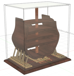
I posted back in June my 3D CAD design for the base, support and cover for my cross section model. The design looked like this:
1664560357593.png

Here are some in-process and completed pics of it along with the model:

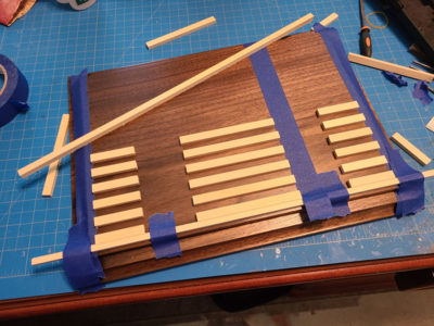
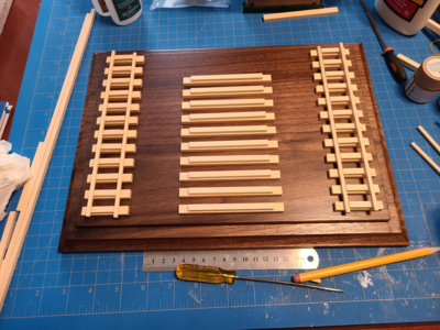
I placed painters tape along the edges of where the timber supports are to go:
1664559151267.png
I made the spacing between the bottom strips the same as the strip width, allowing me to use other strips to maintain an even spacing.

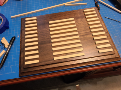
After the first row of timber supports, I had this:
1664559178385.png
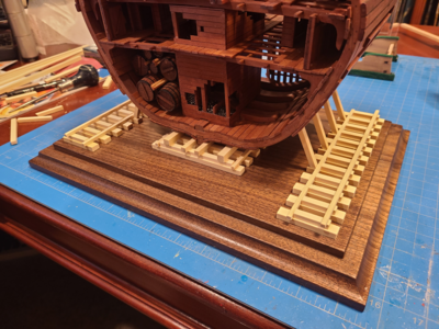
BTW, the support timbers are Alaskan Yellow Cedar from the Modeler's Sawmill, left unfinished and on the rough side, while the base is walnut. I think the cedar gives a good contrast between the walnut base the pear wood model.

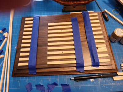
I then placed tape again to help locate the second level of timbers:
1664559277386.png

Second row timber supports are now in place. along with some smaller longitudinal ties:
1664559320238.png

At this point, I've added supports to locate the keel, longitudinal ties on the center support stack,main supports for the hull and inner row of diagonal supports from the outside.
1664559394488.png

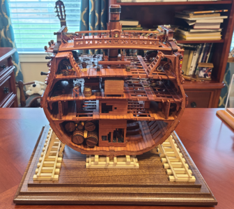
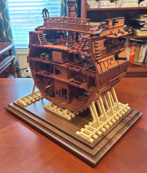
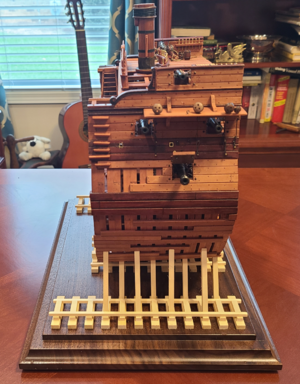
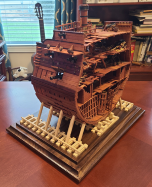
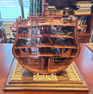
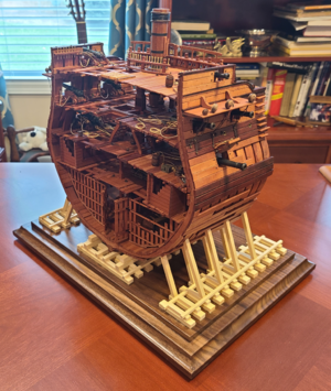
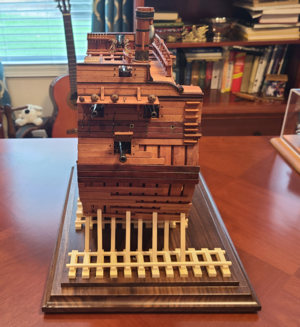
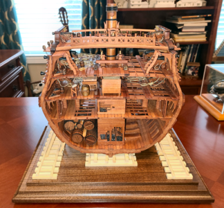
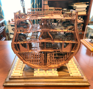
The remaining photos are of the completed model with base, as a final presentation of the completed model:
1664559795027.png
1664559818453.png
1664559841350.png
1664559862479.png
1664559882005.png
1664559980229.png
1664560005426.png

These two shots used a "flash" to help show the inner detail a bit better:
1664560129739.png
1664560154040.png

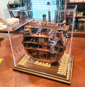
And a final view with the plexiglass cover in place:
1664560183621.png
The blank area in front of the center supports provides room for an engraved brass nameplate, which is on order.

It's been great fun doing this model, and I appreciate all the support, comments and encouragement I've received here. Can't wait for the next project. :)
 
I forgot to mention in my writeup that I decided to mount the cross section permanently to the base. I felt that if I left it just sitting on the construction base, that the base supports would not be very sturdy, and someone would pick the base up, thinking it to be one piece, resulting in the model falling and getting damaged. I used two #6 wood screws up through the walnut base, the timber supports, and into the keel. The diagonal supports were then glued to both the base and the side of the hull, so they would stay in place better and help keep the model in the correct location. I can still work on it this way, if I want to, such as adding a 1/48 scale crew member that was getting dull-coated when these pics were taken.
 
I posted back in June my 3D CAD design for the base, support and cover for my cross section model. The design looked like this:
View attachment 331566

Here are some in-process and completed pics of it along with the model:

I placed painters tape along the edges of where the timber supports are to go:
View attachment 331550
I made the spacing between the bottom strips the same as the strip width, allowing me to use other strips to maintain an even spacing.

After the first row of timber supports, I had this:
View attachment 331551
BTW, the support timbers are Alaskan Yellow Cedar from the Modeler's Sawmill, left unfinished and on the rough side, while the base is walnut. I think the cedar gives a good contrast between the walnut base the pear wood model.

I then placed tape again to help locate the second level of timbers:
View attachment 331552

Second row timber supports are now in place. along with some smaller longitudinal ties:
View attachment 331553

At this point, I've added supports to locate the keel, longitudinal ties on the center support stack,main supports for the hull and inner row of diagonal supports from the outside.
View attachment 331554

The remaining photos are of the completed model with base, as a final presentation of the completed model:
View attachment 331555
View attachment 331556
View attachment 331557
View attachment 331558
View attachment 331559
View attachment 331560
View attachment 331561

These two shots used a "flash" to help show the inner detail a bit better:
View attachment 331563
View attachment 331564

And a final view with the plexiglass cover in place:
View attachment 331565
The blank area in front of the center supports provides room for an engraved brass nameplate, which is on order.

It's been great fun doing this model, and I appreciate all the support, comments and encouragement I've received here. Can't wait for the next project. :)
Beautiful build, so much to take in, great job.
 
Absolutely a great build of both the model and display case.

The work on supports for ship in dock are great.

Where did you get the glass for case, real glass or Plexiglas? and cost?
 
Absolutely a great build of both the model and display case.

The work on supports for ship in dock are great.

Where did you get the glass for case, real glass or Plexiglas? and cost?
Thank you, Kurt. The supports do seem to set it off nicely, and support it well too.

The clear case is acrylic (Plexiglas), 3/16" thick, 5-sided, from ShopPopDisplays.com. Cost me $135, but when I price it out on their site now it comes out less than $110 with free shipping. Could it be the price of something has gone down? Nah!
 
Great build and a nice dust cover

I also have this model on my list as a future model.

Can you tell me the dimensions of the cover are (LxW.H)?

Regards
Henk
 
Great build and a nice dust cover

I also have this model on my list as a future model.

Can you tell me the dimensions of the cover are (LxW.H)?

Regards
Henk
Thank you for the comments. This was my first experience with pear wood, and I hope it's not the last.

Mine is 12 3/8” wide x 8 3/4” deep x 13” high outside. I know others have suggested 3" clearance all around, but at least on this model, that would have been ridiculously large IMHO. I wouldn't have minded it being 1/2" or so shorter, actually.
 
I posted back in June my 3D CAD design for the base, support and cover for my cross section model. The design looked like this:
View attachment 331566

Here are some in-process and completed pics of it along with the model:

I placed painters tape along the edges of where the timber supports are to go:
View attachment 331550
I made the spacing between the bottom strips the same as the strip width, allowing me to use other strips to maintain an even spacing.

After the first row of timber supports, I had this:
View attachment 331551
BTW, the support timbers are Alaskan Yellow Cedar from the Modeler's Sawmill, left unfinished and on the rough side, while the base is walnut. I think the cedar gives a good contrast between the walnut base the pear wood model.

I then placed tape again to help locate the second level of timbers:
View attachment 331552

Second row timber supports are now in place. along with some smaller longitudinal ties:
View attachment 331553

At this point, I've added supports to locate the keel, longitudinal ties on the center support stack,main supports for the hull and inner row of diagonal supports from the outside.
View attachment 331554

The remaining photos are of the completed model with base, as a final presentation of the completed model:
View attachment 331555
View attachment 331556
View attachment 331557
View attachment 331558
View attachment 331559
View attachment 331560
View attachment 331561

These two shots used a "flash" to help show the inner detail a bit better:
View attachment 331563
View attachment 331564

And a final view with the plexiglass cover in place:
View attachment 331565
The blank area in front of the center supports provides room for an engraved brass nameplate, which is on order.

It's been great fun doing this model, and I appreciate all the support, comments and encouragement I've received here. Can't wait for the next project. :)
Good morning. Wonderful cross section. The stand together with the many details you have included has made for a beautiful model. Cheers Grant
 
Just

BRAVO


the presentation with the base is as good as your model :cool:
 
Thanks, guys. It does look very nice on my desk. But a lot of the thanks goes to those who built (at least partially) this kit before me, like you Uwe, ReneK, carlosys, neptune, Adiefenbach, Oldpaperone, Osaul, stan167, and of course Jeronimo with his scratch builds of this ship. The help and ideas one can find on these forums are fantastic!
 
I've been working on the guns for the cross section. There are two 18-pounders, four 12-pounders and two 8-9-pounders (I've read they were both). I posted previously that I got some different barrels for the 8-pounders, and reworked the carriages some, as noted above. I decided to blacken the barrels (and pretty much all brass rings, nails, etc.) using Birchwood Casey Brass Black. It did a perfect job first time on nails and rings; the barrels were a mixed bag:
View attachment 297557

I had expected the bright area around the larger barrel's trunnion, as I had superglued it in place, and could get it all off. I guess just by "playing" with them and all, I'd gotten some areas marked up more than I thought, with something that the alcohol wouldn't remove.

So I cleaned them up some more, using steel wool and a file, and they turned out better the next time:
View attachment 297558

Some notes concerning the use of the Brass Black:

  1. Small parts cannot be "buffed" afterwards, and I find that the black coating rubs off on fingers especially well, and other things. Doesn't really hurt the part, just can make a mess.
  2. Definitely buff the larger parts like the gun barrels with a soft cloth. It brings out a nice sheen.
  3. I only used one coat (soaking) of the Brass Black for most parts. Those that didn't take weren't clean enough so were redone as above.
  4. While the Brass Black liquid is a semi-transparent light blue color, it DOES stain the woods I've checked it on. One one of the other threads, someone asked if it would. It does. Putting a wood finish on afterwards did not remove it or make it less noticeable (like can be done with superglue on wood).
  5. Likewise, if you apply the Brass Black to a pin or other brass part already inserted in the wood, it WILL blacken the brass, but then in turn makes a black stain around the part in the wood. Ugly!
  6. At first I took small storage containers and partly filled them with Brass Black, then placed the brass parts in them to darken. Then rinsed them while in the container, etc. I found that using small food baggies with a small amount of Brass Black in the bottom worked better: I would add one barrel at a time, seal the bag, squish it around to mix the liquid and cover the part, until it was the color I wanted (usually only about a minute), then take the part out to rinse and continue the process. Then add the next barrel or part. I'm sure you shouldn't dip parts in the Brass Black bottle, contaminating the liquid, but using the baggie, I could seal it and add parts later.
  7. The black coating DOES scratch off. Since I think it's designed for guns, possibly multiple coats would prevent that, but I just tried to be careful and touched up any scratched areas I didn't like.
Here are my three sizes of guns atop the 1/48 scale sized Boudriot's drawing:
View attachment 297565
As stated previously, the gun barrels and carriages are close to scale for the 18- and 12-pounders (the barrel averaging the length of the Old and New patterns). I replaced the 8-9-pounder barrels with shorter ones, which are pretty close, and modified the carriages to be closer in size and shape.

A fellow forum member here helped me out with some extremely nice breeching ropes:
View attachment 297567
The larger rope included with the kit was only about half the required size. I think these will look good once attached in position.

On to making the rest of the gun tackles and mounting the larger cannon on the lower gun deck, then starting on the next deck...

Do you recall the diameter of the breaching ropes you used? They look truer to scale than those provided in the kit. I've found a good supplier of quality rope and am trying to decide on the diameters for the 3 different cannon sizes before ordering.
 
Do you recall the diameter of the breaching ropes you used? They look truer to scale than those provided in the kit. I've found a good supplier of quality rope and am trying to decide on the diameters for the 3 different cannon sizes before ordering.
I used 1mm diameter on the 18 pounders, 0.9mm for the others.

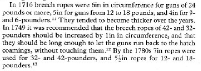
From The Arming and Fitting of English Ships of War, 1600-1815 by Brian Lavery:
1719630409155.png
To get the diameter size in mm, you can use the following formula:

Diameter(mm) = Circumference(in)/pi(3.1416)*25.4/Scale(48) = Circumference(in)/Scale*8.085
So a 7" circumference at 1/48 scale gives 7/48*8.085 = 1.18mm

Hope this helps.
 
Last edited:
I used 1mm diameter on the 18 pounders, 0.9mm for the others.

From The Arming and Fitting of English Ships of War, 1600-1815 by Brian Lavery:
View attachment 456051
To get the diameter size in mm, you can use the following formula:

Diameter(mm) = Circumference(in)/pi(3.1416)*25.4/Scale(48) = Circumference(in)/Scale*8.085
So a 7" circumference at 1/48 scale gives 7/48*8.085 = 1.18mm

Hope this helps.
Perfect! Thanks so much for sharing the reference and what you used.

Love this forum and the help all are willing to give and provide!!
 
Back
Top