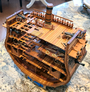
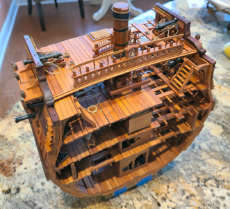
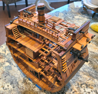
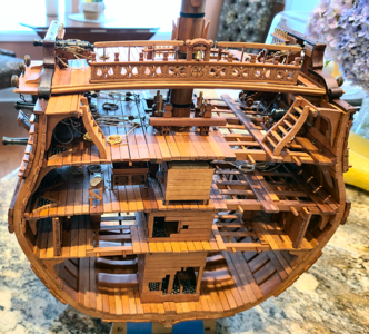
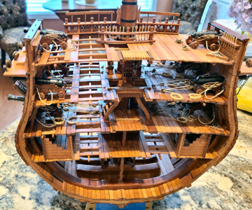
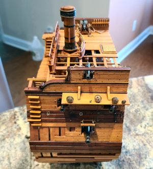
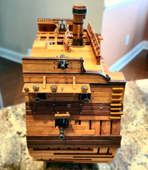
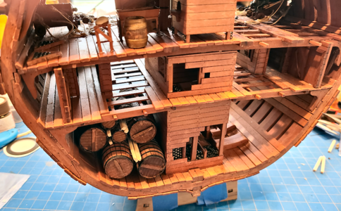
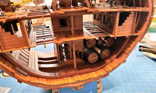
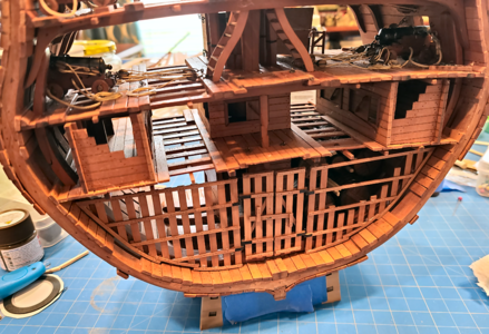
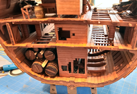
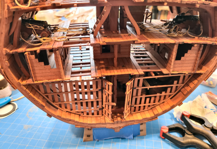
Signet's Bonhomme Richard Cross Section [COMPLETED BUILD]

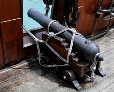
Different decks often housed different caliber cannons - e.g., 36- and 24-pounders on the lower deck, 18 pounders on the middle deck and 12- and 6-pounders on the upper deck. These were often not rigged the same i.e., lighter cannons were rigged differently than the heavier ones based on the difference in recoil.
 
My Question: So, while I'm confused, I've already done the lower two decks. What do you think should be on the uppermost deck? If 2 rings closer to the guns and one toward the center, as shown in 2 of the sources (and on my model), would both tackles to pull the gun back be attached to the single ring toward the center? That would seem to be the only method available. But I wonder why the difference in ring locations from deck to deck? Source-to-source can vary, but being different within a single source is confusing. Redface
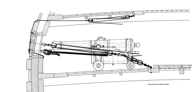
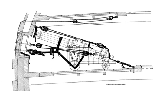
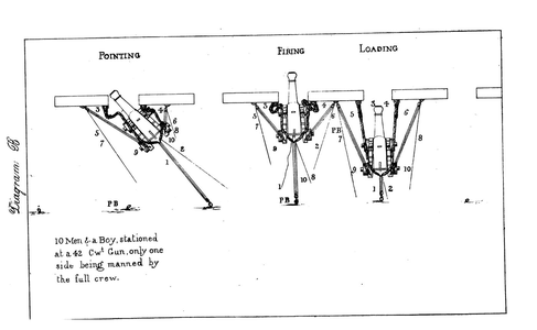
Greetings, Signet. It is a very good question, and many thanks for asking. I believe, IMHO, that both ringbolts behind the cannons are obsolete. Here is why: when the gun fired is will run out immediately, and both ringbolts will obstruct the easy run-out. In such a case, the gun could easily overturn or 'jump' in the wrong direction. (see below)

1656463718780.png

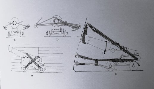
Earlier, before the 18th Century, the single ring (right behind the cannon) was used to secure the cannon while route and heavy sea.

1656465188993.jpeg

1656464117594.jpeg

1656464178412.png

1656464200993.png

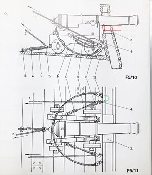
In the late 17Th Century, different methods were used. the carriage was tight to the bulwark rings.

1656464669420.jpeg

The far rings were used to bring back cannons when a gun was aimed in the different directions

1656465494000.png

1656465554883.jpeg
 
Greetings, Signet. It is a very good question, and many thanks for asking. I believe, IMHO, that both ringbolts behind the cannons are obsolete. Here is why: when the gun fired is will run out immediately, and both ringbolts will obstruct the easy run-out. In such a case, the gun could easily overturn or 'jump' in the wrong direction. (see below)

View attachment 316051

Earlier, before the 18th Century, the single ring (right behind the cannon) was used to secure the cannon while route and heavy sea.


View attachment 316053


In the late 17Th Century, different methods were used. the carriage was tight to the bulwark rings.


The far rings were used to bring back cannons when a gun was aimed in the different directions
Thanks for all that information and diagrams, Jim. I agree pairs of close rings would get in the way. Unfortunately, they're on my current model, but may have to change that. Some of your diagrams would work well with a single ring toward the center of the ship, as they attach to the barrel, while others would seem to need two rings, unless two tackles would connect to the same ring. While the center-most rings may not be required during firing, due to the recoil of the gun, if the gun were retracted without firing they would be necessary.
 
In addition to the very good explanations given before.

Smaller guns had often only one ring / block installed at the center of the rear axle - so they needed only one tackle

IMG-9136.jpg

sketch is taken from the Anatomy book of the HMS Granado - british 4pdr
 
Different decks often housed different caliber cannons - e.g., 36- and 24-pounders on the lower deck, 18 pounders on the middle deck and 12- and 6-pounders on the upper deck. These were often not rigged the same i.e., lighter cannons were rigged differently than the heavier ones based on the difference in recoil.
Well, they certainly have different size breech lines for each size, and different size blocks in the tackles as well. I wouldn't have expected the different ring arrangement, but who knows (and they are certainly shown differently). Surely the rings closest to the ship center are necessary to haul an unfired gun back into the ship, and as shown on most drawings, also to hold them in position during times of disuse or sailing, as shown on Jim's drawings.
In addition to the very good explanations given before.

Smaller guns had often only one ring / block installed at the center of the rear axle - so they needed only one tackle

View attachment 316096

sketch is taken from the Anatomy book of the HMS Granado - british 4pdr
Thanks, Ewe. That ring wouldn't be enough to bring the gun all the way back to load, though, as it's too close to the gun. But I agree with your statement about smaller guns, and these are only 6-pounders.
 
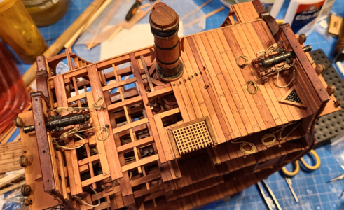
Again, thank you everyone for the wealth of information you have given me. I've read through it all, finding it extremely interesting. In the end, I took the easy way out (but accurate too, I think). I had already added eyes to the model based on the model plans, which also agreed with Boudroit's drawings for the Bonhomme Richard, and similar to some other sources as well. I then reasoned that especially the upper deck should be kept as free from additional tackles and lines as possible, due to the tripping hazard, and the desire in wanting to keep everything ship-shape. I also looked at all completed models I could find in the forums, including Jeronimo's incredible full ship build. So I ended up using only the tackles closest to the outboard, which properly contains and locates the guns. I used the two closest eyes to tie the ends of the tackle ropes into, and made loose coils for the remaining rope, as I feel that without the tackle ropes being secured to an eye (rather than just left loose and coiled), they would not be at all secure. Here's my end result:

1656555151811.png

While there can be confusion as to exactly how the other eyes would be used, I feel confident that the modeled position at least represents what was done at some time, and therefore properly represents the model, which I wanted to do.

Despite the simplistic solution I adopted, I really enjoyed the comments, documentation and illustrations provided by everyone. Modeling isn't just a hobby; it's a real education!
 
Your build looks super - irrespective of the solution chosen, and, as you say, chances are excellent that you may be accurate too! Well done! Thumbsup
 
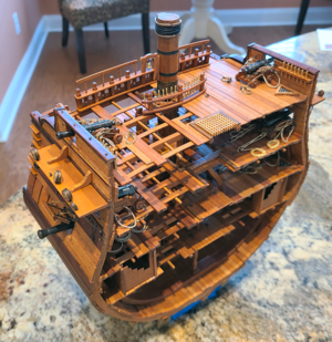
Since I'm reaching a new stage with the build, I thought I'd add some overall pictures of the build (without quite as much clutter in the background):
1656616624919.png
1656616646057.png
1656616668142.png
1656616702436.png
1656616732103.png
The above picture shows the added kneading trough and dough table, in addition to the included bread oven.
1656616815726.png
1656616838215.png
1656616854991.png

Yet to do:
  • Finish the barrels I want to use, and place them in the hold, possibly with stones.
  • Install the fencing partition at one end of the section, photographed here some time ago.
  • Build a display stand as described earlier.
  • Cover the model with a Plexi cover.

Still, the vast majority of the work is done, and I'm starting to thick about the Ragusian Carrack. :cool:
 
also from my side my CONGRATULATIONS
Very well done - I like your section model very much
I am looking forward to follow your next project
 
I can only echo the sentiments of everyone else. I have thoroughly enjoyed following your log and know that you have built a superb model. As I have said before, I am not a fan of section models, but your build has really piqued my interest. Also hats off to Unicorn - it is clearly a great quality kit with excellent timber!
 
Thanks, guys! I just got the wood for the "construction" base today. Have to order the plexi cover, then make a walnut base, and then work on the base assembly. I'll be working on the barrels and hold stuff shortly, but am taking a moment to clean up and organize my den work area before proceeding. I have the nasty habit of getting out tools as I need them, but then they all stay out until the project is done, or I reorganize. Translation: My den is a total mess!
 
Thanks, guys! I just got the wood for them "construction" base today. Have to order the plexi cover, then make a walnut base, and then work on the base assembly. I'll be working on the barrels and hold stuff shortly, but am taking a moment to clean up and organize my den work area before proceeding. I have the nasty habit of getting out tools as I need them, but then they all stay out until the project is done, or I reorganize. Translation: My den is a total mess!

Same here !!! I do exactly the same. :)
Daniel
 
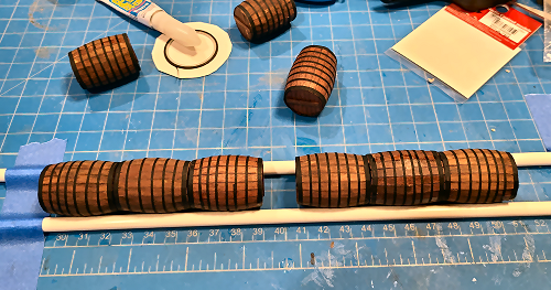
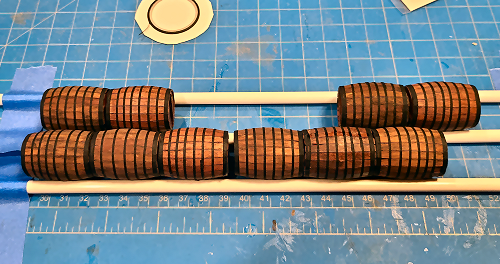
Continuing on with the barrels for the cargo hold, I decided to glue the barrels together, end-to-end, as it's difficult to know when they are each held well in place. I taped two pieces of plastic tubing in place to keep them in line:
1657657205880.png 1657657230805.png
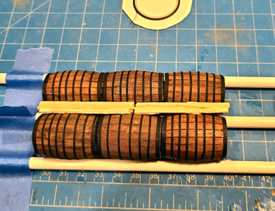
I decided on two rows of 3 large barrels, with 2 rows of two staggered on top.

I then glued 2 of the rows together, with some wood supports between them:
1657657349272.png 1657657318935.png
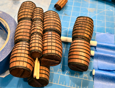
and then added the row with 2 barrels. Decided as well, add some of the smaller barrels including with the kit. I felt I couldn't glue the last two in place until the assembly was mounted in the model, as it's difficult to tell exactly where it will contact the hull.

I ended up adding a second full row of smaller barrels, as well as one on the top:
1657657479347.png

View from the other side:
1657657512088.png
I'm only including barrels on the one side, as I wanted the structural details visible.


Finally added the partition or cage area that came with the upgraded kit (along with other structures and barrels):
1657657684514.png

The partition makes the view from the other side more interesting, as well, as you look into it:
1657657772553.png

Naturally, the doors in the partition are hinged and a crossbar latch holds it in place. Here's a view with the doors open.
1657657830023.png
I intend to display it this way, but until it's finished and in a plexi case, I'll keep it locked so that there's less chance of damage.

I had actually intended to show gravel/stone supporting the lowest level of barrels, but didn't think about it when adding the cage partition, so think I may now not add the stone. I really didn't want to, anyhow, so the partition was probably a "Freudian slip". I think there's a high probability I'd mess that up, and almost certainly couldn't get the stones everywhere I want, and nowhere I don't, so it will probably stay this way.

I've gotten the wood for the construction base, and have ordered the plexiglass 5-sided cover. After I receive it (not trusting dimensions until then) I will make the base, probably walnut, and then add the construction base.

I notice on the photo above that one of my gun tackles had come loose. You see things in photos you can't (okay, I can't) see with the naked eye. Anyhow, got it fixed. Hopefully it will stay.
 
Last edited:
Yeah, another one. There are already so many builds, of such high quality, that I'm sure you're thinking we don't need another one. But I'm hoping that my build might provide some interesting discussion, and the build will definitely be from a professional non-perfectionist viewpoint. Besides, Uwe asked me to do it. :)

I won't go through opening the kit, as there are so many other threads with better coverage. I'll try to cover some things I haven't seen, or perhaps that I've done differently. Please excuse my clumsy start and initial photos; I'm taking pictures with my phone, and am not sure how they will turn out or how this will read, so today's posts are practice, and hopefully they will later improve.

The first thing I did after receiving the kit (full pear version, with interior, barrels, and carved belfrey and railing) for Christmas was to go to Staples. There is just one large sheet of plans, 34" x 48", and of course folded:
View attachment 279359
This makes it a bit hard to work with, especially without ruining the original plans, so I had Staples make 2 full-size copies ($6 each), and also a file of the image in PDF format. I cut up one of the large copies, including small details that related to each other in each separate "sheet", but most are copies of the larger cross sections and views I will be relating to. I am able to easily work with the smaller sheets, and protect them with glass or wax paper during work, so as not to have to keep making copies.

A topic of conversation here about this kit is the lack of English instructions. It appears that Unicorn has heard our pleas, as there is a fair amount of English translations currently included with the kit. If you zoom in on these plans, you will see that area titles and some notes have been translated from Chinese to English. I used Google Translate to view translations to confirm their validity (included translations in general are better than Googles) and make any notes or changes. The 30+ page instruction manual is all photos and pictures, but they have included 6-pages which list Chinese and English for each step:
View attachment 279361
While not elaborate, they are definitely helpful. If anyone building this kit does not have the translations, please let me know and I'll post a copy that you can print.

The optional Interior Kit has instructions on 8 A4 sheets (8.25" x 11.5") and includes both Chinese and English:
View attachment 279387

I decided to start the kit by doing a complete frame, as I knew there would be a lot more to come, and I wanted to practice, get ideas, and maybe get more ideas from you. I chose Frame 2 to start, as 1) It wasn't as visible as 1 or 9, which show at the outside, nor did it contain any cuts for gun ports (more on that later). While the quality of the stripwood is fantastic, as is the quality of the wood with the laser-cut parts, I'm not as happy with the laser-cut parts. First, they're hard to "punch" out, requiring cuts with a blade in the uncut areas. Someone mentioned using a "sturdy" blade, so I used a retractable utility knife. It didn't do badly, but I still had to cut both sides, and I found the long blade would sometimes cut into areas I didn't want. I'm going to try a shorter, thinner scalpel blade to see if it does better. One of my problems is that cataract surgery has left my "good" eye no longer able to see at close distances, so I have to switch to strong reading glasses (3.0, 4.5 and 6.0) to see close stuff. I /think/ I'm cutting right without them, then see my errors with them.

The second disappointment is that the laser cuts are not perpendicular to the surface. Although they appear much larger, I've measured them at 2-6 degrees, probably averaging midway. This results in a bad fit without sanding, a lot of sanding for a good fit, an pieces end up a bit narrower than they should be when done on both sides. Neptune, in his excellent build log, mentioned to keep the same face of the wood upright when building the frames; I suspect the angle, which he also mentions, is the reason for this. I tried switching around trying for a better fir without sanding as much, but that didn't help. These pics give you an idea of the angle (ruler is shoved in tight to a cut joint):
View attachment 279370
The notch where the keel fits into the lower frame (floor?) notches is tight, so it ends up at an angle too:
View attachment 279371
I have to file the openings somewhat larger so the frames will fit the keel when at a right angle.

As much for practice photography and testing, here are a pile of frames before sanding the joining areas:
View attachment 279372
And afterwards:
View attachment 279373
I sanded them at right angles to the outline surface, just taking off the char in this area now. It's easy to sand too much off and not notice it. This applies to the end and "notched" areas, especially. I found that when I had a mating pair about right, I could hold them an "rock" them back and forth, to see if one end was a bit too long, and if so, sand it down to fit better.

For my first frame assembly I used clothespins to secure the joints. I tried the plastic clamps, but the frame thickness was too small. Also, I tried Elmer's Glue-All, but it didn't dry fast enough to suit me, so switched to Titebond Quick & Thick, which I'm happy with so far.
View attachment 279374
This clamping method didn't work out that well for me, though. When doing the second half, I found that the clamping force of the clothespins on the sloped scarf cause the pieces to slide and separate, and I didn't see that until picking the piece of some time later. I used water and slowly separated the pieces on that half, cleaned it up and redid it. This time I placed clothespins like this:

View attachment 279376
This clamped each clamping edge on part of each piece, keeping it snug, but not causing the slide. I've ordered 20 2" metal clamps which I hope to use in the future with better results.

I wasn't sure whether to build up a second half-frame (the two are fastened together) and glue it over the first, or build up the second on top of the first. In the end I chose the second method, feeling I'd keep alignment better, and I think it did:
View attachment 279377
I used two of the keep pieces clamped in place to keep the two floors in alignment. Then added, and clamped, added and clamped.
View attachment 279378

After drying overnight, I sanded the inner and outer char off. Alignment wasn't as good as I'd hoped, and the section is slightly thinner than it should be because of this. I hope my other frames, using a different clamping system, will be better. I've also glued the first four parts of the keel together with the bevels for planking. I found this easier to assemble two pieces at a time, true up, then continue.
View attachment 279381

Speaking of the keel, I've come to my first question (I'm hoping I will get more from you during this thread than I will show you): Shouldn't there be a FALSE KEEL on the model? I'm not that familiar with the construction of French ships, but thought this was pretty much standard: a replaceable timber to protect the keel and its joints. I can easily add a piece to the bottom, of course, but didn't want to if it shouldn't be there.

My second question refers to the jig that is included for frame alignment:
View attachment 279386
I've followed its use in the instructions, but wonder: Why is the large, mostly-rectangular section of the bottom plate left loose to move? I thought at first it was to be removed, but it isn't. The little "bridges", shown in 4 locations with the red arrows, are what attach this section to the rest of the bottom plate. Allowing it to move slightly vertically. The frames don't fit that tight, and I have NO idea why this was done this way. Does anyone know? Also, the 8 rectangular cutouts on the section, one pointed to by the blue arrow, seem to have a specific outline and maybe a purpose? Again, I have no idea.

Okay, that's my first installment. In the future, I will try to include more/better content, less pictures and more "unique" stuff. We will see. PLEASE don't hesitate to point out things I've done wrong, suggest alternate ways of doing things, etc. In short, help make me a better modeler, and this a better model.
Hallo @Signet
we wish you all the BEST and a HAPPY BIRTHDAY
Birthday-Cake

BTW: I lke your new avatar very much - I think it is an Healey 3000, or? One of my favourite classics next to the Jag XK 140
 
Thanks for the birthday wishes! But it's actually my son's birthday today. He's 43, I'm 79. So why the mix-up?? I was a member at the ModelShipWorld.com forums before coming here, posting a log there on my HMS Victory cross section build. At some point, I saw an ad for the Bonhomme Richard cross section model (from China) and asked about it there, and just about got trounced off the Internet! In my Google search, I found ShipsOfScale.com, a great group of more open people who actually BUILT this model, rather than outlawing thought about it. So I joined here, but was concerned if I used the same login and birthday, I'd be identified, by members in both, and banned from MSW (even though I haven't been there for quite a while). So I used the name Signet, a gaming identity I often use, and my son's birth date instead. I really didn't know at the time that this would be my permanent home, but it has become that.

Hope that isn't cause for being outlawed from here; I didn't at the time know how long I'd be here, nor how much I'd enjoy the builds and the builders. I was surprised and shocked when I first got the birthday wishes, and couldn't even find out what date I'd put in for here. When I found it, it all came back to me. I'll convey the birthday wishes to my son; I'd much rather remember his birthday than mine anyhow. He's been having a new house built over the last 15 months (!) and finally closes on it the 27th of this month.

I tried to correct my birth date here, but found I'm unable to change it, so I've made it not visible, so as not to cause additional confusion. But again, I really do appreciate the well-wishes. I like to think that such thoughts are more for the person than for the date, so will accept them graciously, if not legally. :oops:
 
Last edited:
Back
Top