Thanks for your excellent instructions on how to scratch build barrels. Wonderful job you are doing on your ship. In my case, I think I'd like to stick with the parts included in the kit. Mostly, they work quite well; I'm just looking for some tricks to use due to the thin material.Hello Signet, I don't know what options and machines you have, but look at Patrik's report, that would be another way of making barrels. I did the same with my Le Coureur. My options were also limited (just a pillar drill).
Post in thread 'La Renommée - French Frigate 1744 (1/48) - Based on Monographie from J. BOUDRIOT'
https://shipsofscale.com/sosforums/threads/la-renommée-french-frigate-1744-1-48-based-on-monographie-from-j-boudriot.2677/post-45969

-
LUCZORAMA SHIPWRECK SCAVENGER HUNT GIVEAWAY. 4 Weeks of Fun • 1 Legendary Prize ((OcCre’s Fram Ship)) • Global Crew Welcome!
**VIEW THREAD HERE**
You are using an out of date browser. It may not display this or other websites correctly.
You should upgrade or use an alternative browser.
You should upgrade or use an alternative browser.
Signet's Bonhomme Richard Cross Section [COMPLETED BUILD]
- Joined
- Oct 17, 2020
- Messages
- 1,638
- Points
- 488

Buongiorno Sigillo, spero di farti cosa gradita con questi allega
Spent today finalizing the fit of the orlop deck / pump well / shot locker assembly. In and out. In, measure or sight the fit, out and trim or add, back in. I've probably installed this deck hundreds of times by now. And I STILL can't do it quickly.
Also added what I think will be the final planking below the orlop deck. I've cut out (left off) a good bit, so as to show more details of the mast step with wedges, mast, future pumps, etc. I plan on adding 3 sizes of cannon shot to the 3 compartments, one filling it up, the other two lower so as to not obscure details.
In doing some of the tighter areas, like the cannon shot compartments, it's difficult to install a plank at a time, so I've devised a method that simplifies it a bit. Each of the 1x4mm planks for the optional interior parts are laser cut on a sheet. And of course, there are certain points that connect 13 planks together. I've found that if I'm careful, I can cut a short row of planks which include the attachment points, then add a perpendicular plank at one or both ends, to quickly make a small wall assembly. Then install the assembly, which can be sanded to fit, in place. This photo shows cutting a plank "group" from the larger combo-plank:

Yeah, I need a new/better miter box.
Here's the fairly final orlop deck and what's below it with cutouts:


Also added what I think will be the final planking below the orlop deck. I've cut out (left off) a good bit, so as to show more details of the mast step with wedges, mast, future pumps, etc. I plan on adding 3 sizes of cannon shot to the 3 compartments, one filling it up, the other two lower so as to not obscure details.
In doing some of the tighter areas, like the cannon shot compartments, it's difficult to install a plank at a time, so I've devised a method that simplifies it a bit. Each of the 1x4mm planks for the optional interior parts are laser cut on a sheet. And of course, there are certain points that connect 13 planks together. I've found that if I'm careful, I can cut a short row of planks which include the attachment points, then add a perpendicular plank at one or both ends, to quickly make a small wall assembly. Then install the assembly, which can be sanded to fit, in place. This photo shows cutting a plank "group" from the larger combo-plank:
Yeah, I need a new/better miter box.
Here's the fairly final orlop deck and what's below it with cutouts:

Very good work - looking very accurate and precise - Bravo
Good idea to leave the lower part more open with less planking of the well, so you can recognize and see the mast foot etc. much better
Looking at yours now, I would like it much more than mine -> very good decision


If you check only a special topic, building log of one member, you can add in addition the "posted by"
Otherwise you can search for a word on your computer with "F3"
Related to the problem with your barrels - maybe you sho us the problem in a photo, so we can make suggestions
Good idea to leave the lower part more open with less planking of the well, so you can recognize and see the mast foot etc. much better
Looking at yours now, I would like it much more than mine -> very good decision
You can use the "Search function", which could be for a first helpForum Question: Oh, I have like 8 or so threads of BR builds bookmarked for reference, but with some over 20 pages in size, is there a way to search for a word, like "barrel", just within that thread, to look for hints on the above or other topics?
If you check only a special topic, building log of one member, you can add in addition the "posted by"
Otherwise you can search for a word on your computer with "F3"
Related to the problem with your barrels - maybe you sho us the problem in a photo, so we can make suggestions
Thanks, I do too. I considered stain, but didn't want to really darken it, plus I like the look of individual wood pieces, provided they aren't TOO different. I actually wanted to use rub-on poly, but felt the Danish oil brought out a little richer color.I really like the color of the wood treated with the Danish Oil - very warm and lustrous.
I've been experimenting with methods for assembly of the 24 large barrels that are included with the optional interior for the kit. Before building them, however, I fIrstwanted to decide if I wanted to use them. I've checked their actual size against the size of scale barrels. The largest barrel used on this, and most ships of the era, was the Tun, normally used for storing water. A surprise to me, these were usually loaded at the bottom of the cargo and supported and partially surrounded by stone ballast. They were NOT loaded and unloaded to be used or outfitted, they stayed in place, and were filled with a hose and pump, and were emptied the same way. Anyhow, the Tun, according to Boudriot's book on The Seventy Four, was 1.49 meters high and 1.096 meters in diameter. In 1/48 scale, that means the model tun should be 31mm high and 23mm in diameter. The barrels included with this kit turn out to be 33.4mm high and 25.2mm in diameter. or about 8-10% too large.
My first thought was to have my son make 3D printed barrels instead. I would copy Boudriot's loading diagram, with both tun and other sizes of barrels. And if I had the 3D printer and could make them myself, I'd have done that. But that would take on the order of 80 larger barrels, and well over 100 smaller barrels, and as much as he complained when he made the 50 or so barrels for my HMS Victory cross section, I decided not to do that. So, since we're talking about barrels less than 10% too large, and there are always modifications from exact scale in scale models, and since these barrels look SO good, I decided to go with the 24 large ones included, and a yet-to-be-determined number of the small ones (wish they'd included medium size instead of those that are so small).
As those who have built or looked at the kit, each large barrel consists of 11 laser-cut structural pieces, 2 "planked" laser-cut finish pieces in pear (or whatever your kit is made with), and 20 planks. The 11 structure parts don't fit together nearly as tightly as they should, IMHO, so while assembling them is easy, it's a bit messy, with white glue dripping out here and there. After they're assembled, make sure everything is pushed in tightly, the ends are square and in place, and above all, make sure the ends are square with the ribs. It's easy to assemble them and set them down to dry, and not realize that the barrel is tiling to one size, or even assembled in a spiral sort of manner.
Next I put on the finished ends. I tried gluing them in place with white glue, to give me time to get them centered, but quickly found that didn't work: The 0.4mm (0.020") thick wood expands on the "wet" side of the glue, and while you're looking elsewhere, it turns into an arc, with only its center touching the barrel ends. I found it best to use a gel superglue (I used Titebond Instant Bond Wood Adhesive, Gel).
After that has dried, you get to glue on 20 separate wood strips for staves, each properly shaped, into place, curved to the contour of the barrel. While the staves break easily from their laser-cut sheet, I found it necessary to trim the sides of each in 4 places, where they are held to the wood when laser-cutting, also removing additional slivers of wood (which easily puncture a finger - I'm a porcupine now). But once shaped, how best to glue these 20 pieces and hold them in position, finishing the 24 barrels (792 separate parts) in a reasonable time. I tried a number of methods:

My first thought was to use the openings that the barrel forms were cut from to hold the staves in place while gluing.
First, I tried just holding the staves in place, while gluing in the proper position, and that was a nightmare.
At upper left, I took several pieces from the various size barrel baffles, glued them together and sanded them to a taper. The small piece of pear scrap in the bottom was to provide a stop for the end of the barrel and allow the staves to overlap slightly. My procedure was to place the barrel structure in the opening, place a bit of glue on a stave, and stick it in between the structure and the "form", to get one side glued in place. Turns out it wasn't failsafe in locating the staves (or I couldn't see them properly), and when removed after dry, I still had to put glue on the other side of the staves, then hold them all in place, which I did with rubber bands.
I then made another form (upper right in the above pic), which I thought if I glued the center of each stave in place, I could place this form over the end, one or both at a time, rotating and bring the staves in contact with the ends. That was a nightmare as well, and just ended up with sticky staves covering my worktop, floor and fingers.
And of course, I experimented with rubber bands and tape, etc. in trying to keep the staves in position. What a mess!
My final result used tie-wraps, those nylon straps that lock in place, and have to be cut loose. For me, that worked out best, so I'll outline my procedure in adding the staves to the barrels here:
I start with the barrel structure with the finished ends and cross-brace already in place. Again, use superglue for attaching the thin ends; water-based glue warps them. I also attached the cross-braces and left them a bit long, as I intend to sand the ends just a bit.

Apply glue to part of the outside of the barrel. I found I was able to apply it to half of the barrel, enough to attach 20 staves. More was too messy, and less wasn't necessary. When applying the glue, it is VERY IMPORTANT to cover the outer ribs (to properly fix them once curved) and the center rib (to keep it in place in the meantime).

As to glue type, I tried Titebond Quick & Thick, but it dries to quickly to do this. I then went to Elmer's Glue-All, but felt it getting a bit dry on the last stave too. I then ordered Titebond Extend Wood Glue, which has a longer working time. It's a bit runny, but worked better for me. Most of the extra glue you see above stays on the inside and doesn't really make a mess.
Start at a vertical brace, and begin place staves in place. Glue keeps them in place well, just don't touch them after placed. I placed each stave close to its neighbor, but you don't need to push them tight. Fairly loose fit comes out right to 20 staves.

At first, I started keeping the cleaner side of the staves (the side away from the laser burning which can cause more discoloration), but ended up putting them in at random. This is not furniture, after all, and variations are expected
After finishing a glued section, apply more glue and continue.

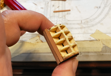
After applying all the staves, you are holding a fully assembled barrel:

I then place a lightweight, 6" long zip-tie around the middle, and tighten it securely. Make sure the staves are at right angle, don't overlap or leave spaces. I can usually accept small variations, as I can always put that side down.

I then place two more zip ties on, near the center, but not as tightly:

Shift the outer ties toward the outside, closing the gaps on the staves, and tighten as you go. You can rotate the ties somewhat to help snug the staves in place. Some want to stick out, rotate to have the smooth are cover them:

Where staves are not held tight, small pieces of scrap can be placed to help keep them in place:

8 barrels now with staves, drying:

After dry, remove the zip ties (they slide off, and can't be used again). Should any staves stick up, I super glue them and use an accelerator to freeze them in place. Here are 3 finished barrels:

The one on the right only has Danish oil on it. I wanted more contrast for them in the hold, so the one of the left has Minwax Dark Walnut stain. I found that using Danish Oil first, then staining over, gave a nice shade and moderated the blotching some, so I'm going that way.
Hope this helps.
My first thought was to have my son make 3D printed barrels instead. I would copy Boudriot's loading diagram, with both tun and other sizes of barrels. And if I had the 3D printer and could make them myself, I'd have done that. But that would take on the order of 80 larger barrels, and well over 100 smaller barrels, and as much as he complained when he made the 50 or so barrels for my HMS Victory cross section, I decided not to do that. So, since we're talking about barrels less than 10% too large, and there are always modifications from exact scale in scale models, and since these barrels look SO good, I decided to go with the 24 large ones included, and a yet-to-be-determined number of the small ones (wish they'd included medium size instead of those that are so small).
As those who have built or looked at the kit, each large barrel consists of 11 laser-cut structural pieces, 2 "planked" laser-cut finish pieces in pear (or whatever your kit is made with), and 20 planks. The 11 structure parts don't fit together nearly as tightly as they should, IMHO, so while assembling them is easy, it's a bit messy, with white glue dripping out here and there. After they're assembled, make sure everything is pushed in tightly, the ends are square and in place, and above all, make sure the ends are square with the ribs. It's easy to assemble them and set them down to dry, and not realize that the barrel is tiling to one size, or even assembled in a spiral sort of manner.
Next I put on the finished ends. I tried gluing them in place with white glue, to give me time to get them centered, but quickly found that didn't work: The 0.4mm (0.020") thick wood expands on the "wet" side of the glue, and while you're looking elsewhere, it turns into an arc, with only its center touching the barrel ends. I found it best to use a gel superglue (I used Titebond Instant Bond Wood Adhesive, Gel).
After that has dried, you get to glue on 20 separate wood strips for staves, each properly shaped, into place, curved to the contour of the barrel. While the staves break easily from their laser-cut sheet, I found it necessary to trim the sides of each in 4 places, where they are held to the wood when laser-cutting, also removing additional slivers of wood (which easily puncture a finger - I'm a porcupine now). But once shaped, how best to glue these 20 pieces and hold them in position, finishing the 24 barrels (792 separate parts) in a reasonable time. I tried a number of methods:
My first thought was to use the openings that the barrel forms were cut from to hold the staves in place while gluing.
First, I tried just holding the staves in place, while gluing in the proper position, and that was a nightmare.
At upper left, I took several pieces from the various size barrel baffles, glued them together and sanded them to a taper. The small piece of pear scrap in the bottom was to provide a stop for the end of the barrel and allow the staves to overlap slightly. My procedure was to place the barrel structure in the opening, place a bit of glue on a stave, and stick it in between the structure and the "form", to get one side glued in place. Turns out it wasn't failsafe in locating the staves (or I couldn't see them properly), and when removed after dry, I still had to put glue on the other side of the staves, then hold them all in place, which I did with rubber bands.
I then made another form (upper right in the above pic), which I thought if I glued the center of each stave in place, I could place this form over the end, one or both at a time, rotating and bring the staves in contact with the ends. That was a nightmare as well, and just ended up with sticky staves covering my worktop, floor and fingers.
And of course, I experimented with rubber bands and tape, etc. in trying to keep the staves in position. What a mess!
My final result used tie-wraps, those nylon straps that lock in place, and have to be cut loose. For me, that worked out best, so I'll outline my procedure in adding the staves to the barrels here:
I start with the barrel structure with the finished ends and cross-brace already in place. Again, use superglue for attaching the thin ends; water-based glue warps them. I also attached the cross-braces and left them a bit long, as I intend to sand the ends just a bit.
Apply glue to part of the outside of the barrel. I found I was able to apply it to half of the barrel, enough to attach 20 staves. More was too messy, and less wasn't necessary. When applying the glue, it is VERY IMPORTANT to cover the outer ribs (to properly fix them once curved) and the center rib (to keep it in place in the meantime).
As to glue type, I tried Titebond Quick & Thick, but it dries to quickly to do this. I then went to Elmer's Glue-All, but felt it getting a bit dry on the last stave too. I then ordered Titebond Extend Wood Glue, which has a longer working time. It's a bit runny, but worked better for me. Most of the extra glue you see above stays on the inside and doesn't really make a mess.
Start at a vertical brace, and begin place staves in place. Glue keeps them in place well, just don't touch them after placed. I placed each stave close to its neighbor, but you don't need to push them tight. Fairly loose fit comes out right to 20 staves.
At first, I started keeping the cleaner side of the staves (the side away from the laser burning which can cause more discoloration), but ended up putting them in at random. This is not furniture, after all, and variations are expected
After finishing a glued section, apply more glue and continue.
After applying all the staves, you are holding a fully assembled barrel:
I then place a lightweight, 6" long zip-tie around the middle, and tighten it securely. Make sure the staves are at right angle, don't overlap or leave spaces. I can usually accept small variations, as I can always put that side down.
I then place two more zip ties on, near the center, but not as tightly:
Shift the outer ties toward the outside, closing the gaps on the staves, and tighten as you go. You can rotate the ties somewhat to help snug the staves in place. Some want to stick out, rotate to have the smooth are cover them:
Where staves are not held tight, small pieces of scrap can be placed to help keep them in place:
8 barrels now with staves, drying:
After dry, remove the zip ties (they slide off, and can't be used again). Should any staves stick up, I super glue them and use an accelerator to freeze them in place. Here are 3 finished barrels:
The one on the right only has Danish oil on it. I wanted more contrast for them in the hold, so the one of the left has Minwax Dark Walnut stain. I found that using Danish Oil first, then staining over, gave a nice shade and moderated the blotching some, so I'm going that way.
Hope this helps.
Attachments
Here's one of the tun barrels with the proper hoops on it. Not that neatly done; I have to figure out a way to space them more evenly. But considering you won't see them from the side anyhow, it's probably okay.

The bunghole would be located in the center, on top, as loaded, and as I understand it, after filling, a piece of sailcloth would be nailed over top of the plug.
BTW, I used 1mm wide Kyosho Micron tape, as has been recommended here. Depending on adherence, I may spray them with Dullcoat or similar to keep it adhered.
- Joined
- Oct 17, 2020
- Messages
- 1,638
- Points
- 488
I'm having a problem finding the right part for a portion of the mast step area. Stan167 has the clearest picture I've found of this, so I will post his pic (hopefully he doesn't mind):
View attachment 281875
(Wonderful nails/bolts/treenails BTW; it's a shame it all gets covered up by the pump well.)
I've identified all the parts except the slanted pieces that form a wedge at the bottom of the mast, identified with red arrows above. On the plan cross section these are identified as parts 1512:
View attachment 281878
Below is a picture of parts 1512, showing where they were taken from, confirming the right part number:
View attachment 281876
This can't be right. For reference, a longitudinal section drawing shows this area as:
View attachment 281877
I've found the pieces 1511, which are just rectangles which are to be tapered and installed at an angle (Although I don't see anything specified to form the triangular shaped piece to either side which keeps the pieces at the correct angle).
Anyhow, I can't find the correct pieces for the parts pointed to with red arrows above. The shape should be a really fat T, basically a rectangle, with the upper half of the rectangle extended to fit into the top half of members on either side. Based on the slot size on either side, it should be of 4mm stock.
Anyone have any ideas where those are? Or do I have to make them myself (not that it would be difficult). I'll be really embarrassed if someone points out where the part is, but it will be worth it to have the Good morning Seal, see if this image can be of help to you, my opinion on the Kits, you just have to assemble as per instructions but if you start modifying you do nothing but damage, morale you will never have a real model

Thank you, Frank48. I found the pieces they intended me to use (right part number), but they were rectangular, and IMHO to properly fit in the mast step area and wedge the mast in place, they should be trapezoidal in shape, so I made new pieces to fit the area, of which I posted a picture previously on the finished mast step area. They do look like those published in books and on Jeronimo's section and model, so I think I'm okay.
Well, I just finished assembling the last of my large barrels. I still have to superglue down any stray staves, stain & oil them and apply the tape hoops.
So, I thought I'd try just one of the small barrels. COMPLETE FAILURE! My technique, described and pictured above, relies on being able to hold the ends of the barrel, while applying glue and staves to the outer surface. But the ends are too tiny, the staves too long, and so I ended up holding a completed barrel that was indistinguishable from a bunch of broken toothpicks and half an ounce of white glue! Cleanup on aisle mine! Not quite the quality and appearance I was going for.
I'm thinking the only way to do these will be using superglue. Either gluing the center, then the ends, one stave at a time, or maybe doing one end, then the other. If anyone has any other thoughts, suggestions, ideas on this, I'd love to hear them.
Or - maybe I'll either not use any small barrels, or con my son into making some 3D printed ones. Problem with those is they won't look anything like the ones I've built, so could only be used in different areas.
Speaking of - the four "cabins" as they're called in the instructions on this model were actually vegetable storage rooms. The main vegetable that seems to be used at this time was dried beans. Does anyone know what type of containers would be used for these beans (type and size), and maybe what other container types might have vegetables for these rooms. Perhaps I can include some small barrels or other storage in one or more of these rooms for added detail.
OK, I solved the problem of handling and gluing staves on the small barrels. Here's a picture of my setup, easily made:

I've taken a piece of scrap from the outside of the staves sheet, and taped it to my work table as a guide. Then I took a narrow piece of painters tape and centered one of the staves on it, and moved it to be parallel and in contact with the scrap guide, then taped the painters tape in place. Of course the painters tape is in place sticky side up and allows placement of the staves on it. (When doing the next barrel, I removed everything but the scrap guide, and put the same pieces on top, rather than under as shown in my first try above).
Place 12 staves against the scrap guide, and more or less centered on the tape. They should not touch each other, but not be too far away either, in order to space around the barrel.

I've found that especially with the small barrels, the staves can be both discolored and a bit uneven when they look good from the other side. So I place them bad-side-up on the tape, so the opposite (good) side will be to the outside on the barrels.
Using a razor knife, cut one side of the painters tape right up against the stave at the end, and the other side a bit longer to handle and overlap:

Place the barrel with glue covering it in place, centered on the staves:

Wrap up the tape with staves attached around the barrel, and overlap the tape so as to keep the first and last staves close against each other:

After overlapping tape, keeping the staves aligned, you have this:

Place a zip tie near each end of the barrel, somewhat loose at first:

As with the large barrels, alternately slide each zip tie toward the side and tighten, alternating sides as well. Do this until each zip tie is right at the edge of the barrel, and as tight as you can get them. Don't worry if they pop off; just throw them in the trash and try again.
You can rotate the zip ties to help even out the staves and make them flat, but usually one stave under the tightening part of the zip tie will not lie flat:

I then use a toothpick to shove into the space above the raised stave to force it down and further tighten then zip tie:

Once both sides are done, set the assembly aside to dry and work on the next:

I also tried putting glue on the staves rather than the barrel structure. This is easier and neater, and if you're careful, glue won't squeeze out much at all.

As with the larger barrels, after they're dry, I touchup-sand the ends of the staves and any areas of glue, and super-glue any loose staves in place, which is not many if you work carefully. I'll post another pic in the next post of the finished barrels.
Wish I'd figured this system out before finishing the 24 large barrels. They could easily be done using the same method to attach the staves, and would have resulted in a quicker and neater job. Oh well, you live and learn.
I've taken a piece of scrap from the outside of the staves sheet, and taped it to my work table as a guide. Then I took a narrow piece of painters tape and centered one of the staves on it, and moved it to be parallel and in contact with the scrap guide, then taped the painters tape in place. Of course the painters tape is in place sticky side up and allows placement of the staves on it. (When doing the next barrel, I removed everything but the scrap guide, and put the same pieces on top, rather than under as shown in my first try above).
Place 12 staves against the scrap guide, and more or less centered on the tape. They should not touch each other, but not be too far away either, in order to space around the barrel.
I've found that especially with the small barrels, the staves can be both discolored and a bit uneven when they look good from the other side. So I place them bad-side-up on the tape, so the opposite (good) side will be to the outside on the barrels.
Using a razor knife, cut one side of the painters tape right up against the stave at the end, and the other side a bit longer to handle and overlap:
Place the barrel with glue covering it in place, centered on the staves:
Wrap up the tape with staves attached around the barrel, and overlap the tape so as to keep the first and last staves close against each other:
After overlapping tape, keeping the staves aligned, you have this:
Place a zip tie near each end of the barrel, somewhat loose at first:
As with the large barrels, alternately slide each zip tie toward the side and tighten, alternating sides as well. Do this until each zip tie is right at the edge of the barrel, and as tight as you can get them. Don't worry if they pop off; just throw them in the trash and try again.
You can rotate the zip ties to help even out the staves and make them flat, but usually one stave under the tightening part of the zip tie will not lie flat:
I then use a toothpick to shove into the space above the raised stave to force it down and further tighten then zip tie:
Once both sides are done, set the assembly aside to dry and work on the next:
I also tried putting glue on the staves rather than the barrel structure. This is easier and neater, and if you're careful, glue won't squeeze out much at all.
As with the larger barrels, after they're dry, I touchup-sand the ends of the staves and any areas of glue, and super-glue any loose staves in place, which is not many if you work carefully. I'll post another pic in the next post of the finished barrels.
Wish I'd figured this system out before finishing the 24 large barrels. They could easily be done using the same method to attach the staves, and would have resulted in a quicker and neater job. Oh well, you live and learn.
Here is a completed large and small barrel:

The striping tape used for the hoops isn't sticking well. I may have to put a coat of Dullcoat on first, to see if it sticks better, then another to better adhere the tape.
As mentioned above, for this scale, the large barrel is about 8% larger than a TUN, the largest barrel normally used, used for water. The small barrel is roughly the size of a HOGSHEAD, but a little longer and smaller in diameter. It should have 4 hoops across the center rather than 3, but I was having so many problems getting the glue to stick, I simplified on this one.
Continuing on, I built the two sides of the Pump Well & Shot Locker room over the templates provided, modifying them some to provide cutouts for detail visibility. Building the ends, then, required that they be fasted to the sides during building, as they have no corner posts:

The last of the four sides being built a plank at a time while the building assembly is in place on the orlop deck:

The completed structure, oiled. Not sure when I'll attach it to the orlop deck, but probably not until the storage rooms are built and decking is determined


Working on arranging the orlop deck planking now. Trying to maintain a 1324 continuous sequence, while providing logical cutouts for visibility. As I'm sure you all know, you can spend hours planning something that no one will ever notice. But it's part of the fun of building this kit, which I am really enjoying.
I'm a bit concerned: I planned on this being my last build before I die, but it's going quicker than I had planned. Maybe I need to re-plan. ;-)
The last of the four sides being built a plank at a time while the building assembly is in place on the orlop deck:
The completed structure, oiled. Not sure when I'll attach it to the orlop deck, but probably not until the storage rooms are built and decking is determined
Working on arranging the orlop deck planking now. Trying to maintain a 1324 continuous sequence, while providing logical cutouts for visibility. As I'm sure you all know, you can spend hours planning something that no one will ever notice. But it's part of the fun of building this kit, which I am really enjoying.
I'm a bit concerned: I planned on this being my last build before I die, but it's going quicker than I had planned. Maybe I need to re-plan. ;-)
Very good work and progress -
There is no time for dying - still a lot to do with this section model and there are also other model kits waiting to be build
There is no time for dying - still a lot to do with this section model and there are also other model kits waiting to be build
Decided to do most of the outer hull planking next. Otherwise, I might be damaging installed components when cutting gun ports, etc. I think this is all the planking I'm putting on the outer area, except of course continuing above the gun ports. I tried to maintain a 13524 plank layout from keel to top.

(Trying to blur out my messy work area, which takes away from the object at hand.)


I have a question about deck assembly procedure: As shown previously in this thread, I've made Deck3 (orlop deck) completely removable at this point, so I can remove it to work on details, etc., then put it back in, and finally, when I'm ready, glue it in place. This is possible because the hull is wider above the orlop deck than at the deck, so I can insert the deck higher, then lower it to its final position. With the next couple decks, he hull is NARROWER than at the deck, as it narrows towards the top. So I will be unable to do that. I think I have two choices:
1) Build the deck, complete, then SLIDE it into place, inserting planks between the beams to finally locate it at gluing. I like this because, as with the orlop deck, and can insert and remove, and work on orlop deck detail, etc., until it's in its final location. The only downside I see is that the "cabins" which are located on the orlop deck would have to be lower than the beams, and not built up into them as the instructions show.
2) Build the deck in place, beams first, then bracing, stiffeners, planking, etc. That is how the instructions show, but I see all kinds of problems with that, like I'd have to Danish oil the cross members, then the bracing, the underside of the decking, etc. before placing them, as it won't be possible to access the lower areas otherwise.
How do you build decks like this (gun decks)? Has it worked better for you, and why?
(Trying to blur out my messy work area, which takes away from the object at hand.)
I have a question about deck assembly procedure: As shown previously in this thread, I've made Deck3 (orlop deck) completely removable at this point, so I can remove it to work on details, etc., then put it back in, and finally, when I'm ready, glue it in place. This is possible because the hull is wider above the orlop deck than at the deck, so I can insert the deck higher, then lower it to its final position. With the next couple decks, he hull is NARROWER than at the deck, as it narrows towards the top. So I will be unable to do that. I think I have two choices:
1) Build the deck, complete, then SLIDE it into place, inserting planks between the beams to finally locate it at gluing. I like this because, as with the orlop deck, and can insert and remove, and work on orlop deck detail, etc., until it's in its final location. The only downside I see is that the "cabins" which are located on the orlop deck would have to be lower than the beams, and not built up into them as the instructions show.
2) Build the deck in place, beams first, then bracing, stiffeners, planking, etc. That is how the instructions show, but I see all kinds of problems with that, like I'd have to Danish oil the cross members, then the bracing, the underside of the decking, etc. before placing them, as it won't be possible to access the lower areas otherwise.
How do you build decks like this (gun decks)? Has it worked better for you, and why?
I took a detour, and decided to work on the partition that goes across the hold on the aft of the cross section. I started by tracing the inside outline of the the hold on a piece of thick paper, making note of specific locations, and covering it with wax paper. I also bent two pieces of the 1mm x 2mm stripwood used for the bracing into rough radii, and after letting them dry overnight, started by layout out the outer pieces:

BTW, while the drawings included with the inside details kit are well done, they are NOT FULL SIZE. In general, they are smaller than the model, by a fair amount. So use them for reference, but watch out using them for dimensions other than very small ones.
Some weights help hold the pieces in position while I superglue them and use accelerator to

I decided to leave one side more open than the other on this structure. Basically, the hold on one side will have barrels (which obscure many kit details), while the other side will not have any, to better view the details of the kit. The opened structure will go on that side, allowing a better view of the mast step and mounting, pumps, etc.

Here I've also filled in a few pieces of scrap to reinforce areas where the frame has butt joints, to strengthen the assembly. I left the two sides connected at this stage, and also while making the doors, although they didn't end up as square as I'd hoped using this method.
I'll finish and mount the assembly after I'm all done detailing the hold and no longer need access to the lower areas. In the meantime, I'll just set it asside. Note that I've made the doors in one piece with hinges, then will spit the one piece into the two doors. Again, I'd hoped this would align better, but it didn't. Once the assembly is mounted, not just shoved into the hull bottom, I think it will look better. Both doors hinge, and will be left open for viewing. I'm also adding a cross bar locking device for the doors; The mounts with notches are shown on the doors, but the rotating bar is off until later.

BTW, while the drawings included with the inside details kit are well done, they are NOT FULL SIZE. In general, they are smaller than the model, by a fair amount. So use them for reference, but watch out using them for dimensions other than very small ones.
Some weights help hold the pieces in position while I superglue them and use accelerator to
I decided to leave one side more open than the other on this structure. Basically, the hold on one side will have barrels (which obscure many kit details), while the other side will not have any, to better view the details of the kit. The opened structure will go on that side, allowing a better view of the mast step and mounting, pumps, etc.
Here I've also filled in a few pieces of scrap to reinforce areas where the frame has butt joints, to strengthen the assembly. I left the two sides connected at this stage, and also while making the doors, although they didn't end up as square as I'd hoped using this method.
I'll finish and mount the assembly after I'm all done detailing the hold and no longer need access to the lower areas. In the meantime, I'll just set it asside. Note that I've made the doors in one piece with hinges, then will spit the one piece into the two doors. Again, I'd hoped this would align better, but it didn't. Once the assembly is mounted, not just shoved into the hull bottom, I think it will look better. Both doors hinge, and will be left open for viewing. I'm also adding a cross bar locking device for the doors; The mounts with notches are shown on the doors, but the rotating bar is off until later.
Continuing on with the outside planking, I decided to go this way because during the course of trimming gunports and such, I am manhandling the cross section structure to this point, and feel if there were much detail internal installed, it would both be more difficult to reach, and I'd end up ruining something.
I'm ship-terminology-challenged, so don't know what the "board" is on ships that the shrouds and deadeyes and such attach to. So I'll just call it the "board" here. I see it referred to as Channels, but don't know if that
The wood moulding in the kit that is inline with the board, and above the board, and possibly below the board, is not spelled out anywhere very well. The Channels detail shows 2x2 strip above the board, and part 1404 in front of it, but given the thickness of the board (3mm), the piece 1404, which appears done with a fancy moulding cut, would have to be at least 5mm wide, and the cutter included to make fancy mouldings only goes to 4mm:

Add this to the fact that almost every kit I've seen built, including the manufacturer's, has been done differently. Possibly because of the above reasons.
So, I decided to make mine in 3 pieces: one 3mm wide (the thickness of the board) in front of it, and 2mm pieces both above and below the board. And try to make the 3 pieces some version of a moulding (I have yet to make a decent moulding with the kit-included razor cutter). This isn't too far away from cross section plans of the original Bonhomme Richard (shown below in red):

The kit recommends painting this moulding black, but I think areas such as that I might end up just staining a darker brown, so used some 2x3mm walnut strips I had left from my Corel HMS Victory cross section (I'm very limited to wood I have on stock, not having built umpteen kits in the past), so felt the walnut might look good here. The board is shown in place here, but without the upper strip or board:

I carved a groove down the center strip, trying to make the 3 pieces look more like a combination proper moulding.
The picture below shows the bottom strip in place and the center one as well:

I then installed the board and upper moulding, with everything clamped tightly in place, but WITHOUT gluing the board in (just allowing room for it). I felt future manhandling might make the board a victim, so this way I can add it later.

Thus, the board can be removed and added later, toward the end of the build. You can see where it will fit here:

Continuing the planking, and adding the two scroll pieces, I felt the lower one needed an extension, so made one to try to match. Blackened both with a Sharpie to match, probably need another coat:

Funny, to my eyes (unaided) that strip behind the moulding looks pretty neat; the waves (lack of straightness) don't show up in person as well, but photos show things even the eye can't see (or didn't want to). Or maybe it's my almost 79 year old eyes. I'll work on it, try to make it look better. Promise. But I still like it there. Oh, and upper gun port hasn't been opened up yet.
(Note to self: Try to take photos more out-of-focus, so as to hide defects. You're not Uwe, you know, you're YOU.)
I'm ship-terminology-challenged, so don't know what the "board" is on ships that the shrouds and deadeyes and such attach to. So I'll just call it the "board" here. I see it referred to as Channels, but don't know if that
The wood moulding in the kit that is inline with the board, and above the board, and possibly below the board, is not spelled out anywhere very well. The Channels detail shows 2x2 strip above the board, and part 1404 in front of it, but given the thickness of the board (3mm), the piece 1404, which appears done with a fancy moulding cut, would have to be at least 5mm wide, and the cutter included to make fancy mouldings only goes to 4mm:
Add this to the fact that almost every kit I've seen built, including the manufacturer's, has been done differently. Possibly because of the above reasons.
So, I decided to make mine in 3 pieces: one 3mm wide (the thickness of the board) in front of it, and 2mm pieces both above and below the board. And try to make the 3 pieces some version of a moulding (I have yet to make a decent moulding with the kit-included razor cutter). This isn't too far away from cross section plans of the original Bonhomme Richard (shown below in red):
The kit recommends painting this moulding black, but I think areas such as that I might end up just staining a darker brown, so used some 2x3mm walnut strips I had left from my Corel HMS Victory cross section (I'm very limited to wood I have on stock, not having built umpteen kits in the past), so felt the walnut might look good here. The board is shown in place here, but without the upper strip or board:
I carved a groove down the center strip, trying to make the 3 pieces look more like a combination proper moulding.
The picture below shows the bottom strip in place and the center one as well:
I then installed the board and upper moulding, with everything clamped tightly in place, but WITHOUT gluing the board in (just allowing room for it). I felt future manhandling might make the board a victim, so this way I can add it later.
Thus, the board can be removed and added later, toward the end of the build. You can see where it will fit here:
Continuing the planking, and adding the two scroll pieces, I felt the lower one needed an extension, so made one to try to match. Blackened both with a Sharpie to match, probably need another coat:
Funny, to my eyes (unaided) that strip behind the moulding looks pretty neat; the waves (lack of straightness) don't show up in person as well, but photos show things even the eye can't see (or didn't want to). Or maybe it's my almost 79 year old eyes. I'll work on it, try to make it look better. Promise. But I still like it there. Oh, and upper gun port hasn't been opened up yet.
(Note to self: Try to take photos more out-of-focus, so as to hide defects. You're not Uwe, you know, you're YOU.)
Very good progress - you are a very fast modeler
and it is looking very very good
btw: I like your way of partly planking the outer hull, so we can see the structire of the frames behind very good
It is getting a very good model - Bravo!
and it is looking very very good
btw: I like your way of partly planking the outer hull, so we can see the structire of the frames behind very good
It is getting a very good model - Bravo!