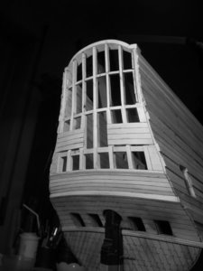
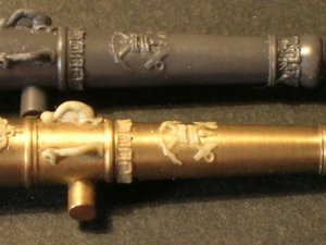
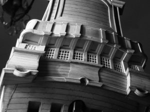
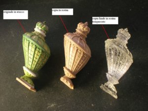
That would be awesome - thanks, Nigel!
-

Win a Free Custom Engraved Brass Coin!!!
As a way to introduce our brass coins to the community, we will raffle off a free coin during the month of August. Follow link ABOVE for instructions for entering.
-

PRE-ORDER SHIPS IN SCALE TODAY!
The beloved Ships in Scale Magazine is back and charting a new course for 2026!
Discover new skills, new techniques, and new inspirations in every issue.
NOTE THAT OUR FIRST ISSUE WILL BE JAN/FEB 2026
You are using an out of date browser. It may not display this or other websites correctly.
You should upgrade or use an alternative browser.
You should upgrade or use an alternative browser.
Soleil Royal by Heller - an Extensive Modification and Partial Scratch-Build by Hubac’s Historian
- Thread starter Hubac’s Historian
- Start date
- Watchers 81
-
- Tags
- 1689 heller hubac refit soleil royal
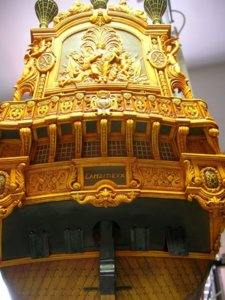
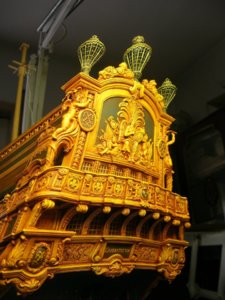
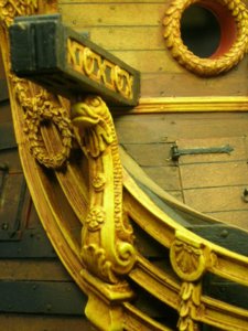
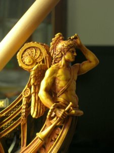
JUST TRULY WORKS OF ART, WHAT MORE CAN YOU SAY, amazing. Don
Nigel - thank you for posting these. This guy really is a talent.
Today, I enjoyed reading through your Sovereign log. There were a lot of really good and interesting modifications, there. The German book on the Sovereign really looked interesting.
So far, I’ve had mixed experience with German language texts. Uber Den Wellen was quite difficult to parse through Google Translate. On the other hand, Versailles Der Meer translates beautifully. In fact the German translation of Hayett’s antiquated French description of the Royal Louis, into English was far more vivid than antique French directly into English. I really enjoyed Versailles Der Meer. It had much more to say about the ships, themselves, than Uber Den Wellen, or Daniel Desert’s La Royale.
Soon, I will check out your Caroline log.
I have talked to Nino about a year ago,and from his facebook posts he started a new model,I asked him about it but since than nothing.
Just remembered another very interesting model in scale 1:48 under construction by Michel Saunier
In the french forum of Gérard you can find building log(s) and several discussions about the ornamentic of the Soleil Royal - I think it will be very interesting for you to take one or two looks inside....
Start:

 5500.forumactif.org
Intermediate log (closed for further posts):

 5500.forumactif.org
actual part:

 5500.forumactif.org
In the french forum of Gérard you can find building log(s) and several discussions about the ornamentic of the Soleil Royal - I think it will be very interesting for you to take one or two looks inside....
Start:

Soleil Royal 1693
Grâce à notre ami Monsieur Lemineur, dans sa monographie du Saint Phillippe, abordant le sujet du Soleil Royal, un voile se déchire envers le Tanneron. Nous nou
Intermediate log (closed for further posts):

Le Soleil Royal au 1/48 par Michel Saunier
Bonjour. Concernant le barbu, à gauche (la mienne pas la sienne) on devine qu'il tient une queue terminée par une sorte de nageoire en forme de bouquet de l'aut
actual part:

Le Soleil Royal au 1/48 par Michel Saunier
Bonjour J'apprendrais sûrement quelque chose ! Michel Saunier a écrit:Pendant que je dépouille le brut d'Apollon, le forum roupille tranquillement, c'est le p
Zoly - a little while ago, I found just a few pics of what looked to be a very interesting San Felipe scratch-build. I think it was Nino’s model, and I may have found it on the Italian Arsenal site. It wasn’t a full frame-up, but a balsa and ply bulkhead construction like Marc Yeu’s SR. Anyway, the lines were beautiful, but I haven’t seen it since.
Michel Saunier is another gentleman with whom I struck up a correspondence. I had been following him for years, and have seen much of his older build log. Not long after we started writing, he brought his build log to MSW. He doesn’t post there often, though, so I will definitely use the link you provided to see where he’s at now.
Michel is a fascinating person. he is sort of the patriarch of Soleil Royal obsessives, like myself and a handful of others, and he has been very helpful to all of us, in our individual quests. Marc Yeu is his protege. After scrapping his first attempt at the so-called “Royal-Balsa,” which was a closer adherent to the Tanneron model, Marc worked with Michel to reconstruct his hull form from the known dimensions and geometric parameters of the original ship. Together, they prototyped and cast an armament of SR’s very ornamental guns, each in their respective scales. They are each building very different models of the ship, and each has much to say about her at two very different stages of her existence.
One thing is certain, though; if it weren’t for the efforts of Michel Saunier, I don’t think any of us would be having these sorts of conversations about Soleil Royal. His work and perseverance through a very demanding research and design phase - not to mention the building of the model - has sparked more debate than any of the rest of us combined.
Thank you, gentleman, for the links and tips!
Last edited:
This is incredible--beautiful work and an amazing source of interesting detail about the Soleil Royal.
Designing of these reverse-curve pedestals and the paneling, in-between, has been giving me fits. As a reminder of Berain’s layout:

This is a challenging thing to approximate onto the Heller architecture. My first break in drawing came after much erasing and re-drawing, and I still wasn’t happy with the result:
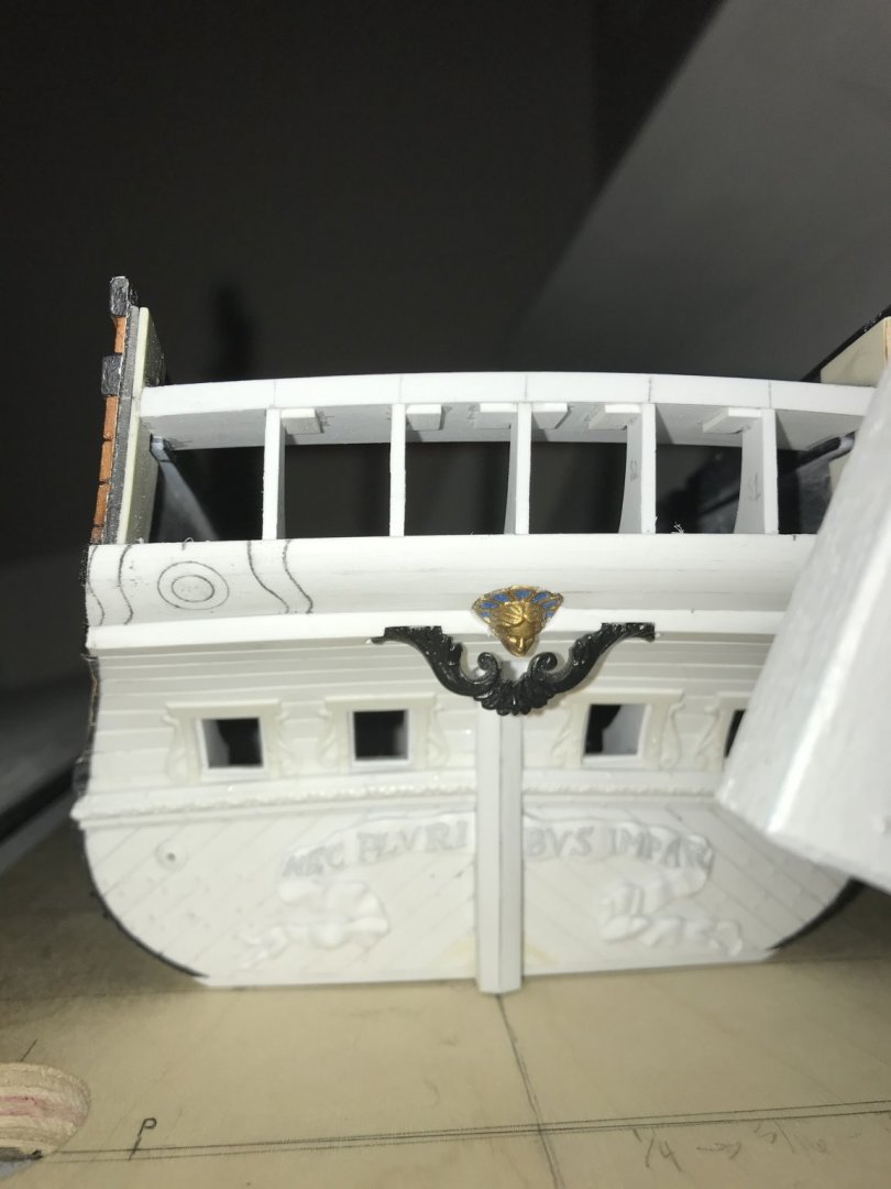
I liked the in-board pedestal shape, but I didn’t like the relationship of rake, relative to the outboard pedestal. I also wasn’t quite sure that the circle was the right diameter.
After allowing it to sit for a few days, I came to a realization about Berain’s drawing. Although he does indicate balcony overhangs with shadowing, the drawing is, otherwise, presented as thoroughly one-dimensional, without any foreshortening of perspective for the rake of the stern.
In other words, in order to arrive at a closer impression of what he drew, one must design with the more likely vantage point in mind; as though you were looking at it straight-on, but from a level plane or above.
After much re-drawing, here is how the shapes change when viewed from below:
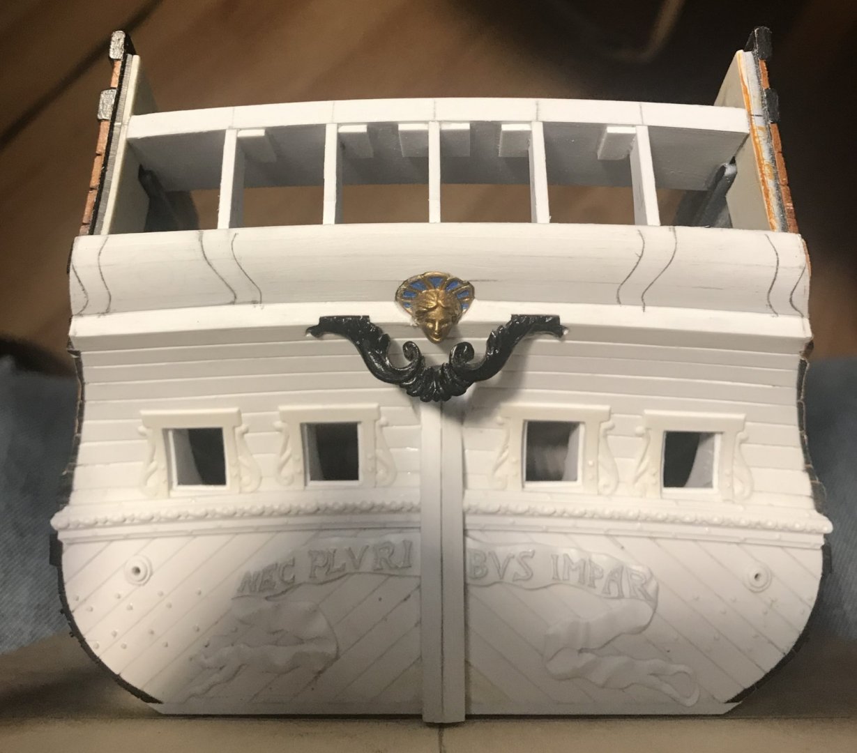
And then, above:
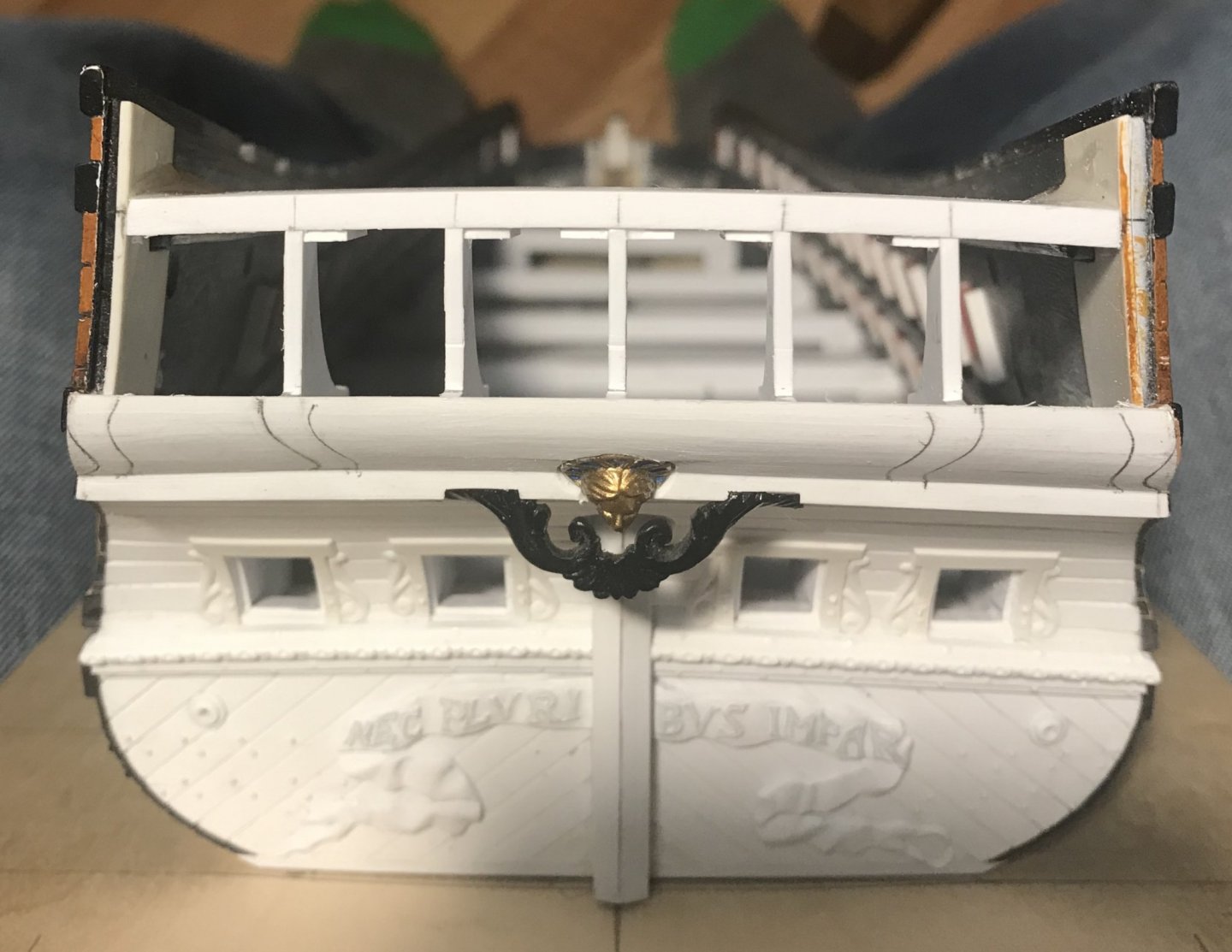
Now, the layout looked right to me, or at least as close to right as the Heller architecture will allow.
Once I was sure that I liked my shapes, I double stuck a scrap of vellum to just beneath the crease of the stern counter. I, then used my finger nail to sharpen that crease into the vellum.
Then, very carefully, I mapped the reverse curves and paneling onto the vellum with a series of dots that were close enough to accurately fair them, once the paper was removed.
After glue-sticking the paper to a scrap of oaktag, I faired and darkened all of my lines, and finally cut out the three main elements with a sharp matte-knife:
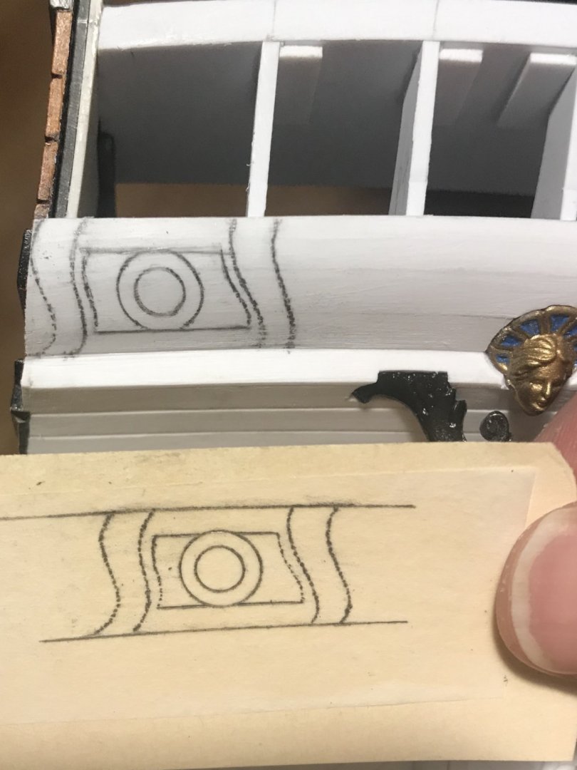
It may appear that the top reveal above the panel is too large, however, there will be a small cove moulding beneath the overhang of the top transitional moulding, and this will balance out the weight of the reveals. As for the bottom reveal, the aforementioned foreshortening of perspective takes care of that issue.
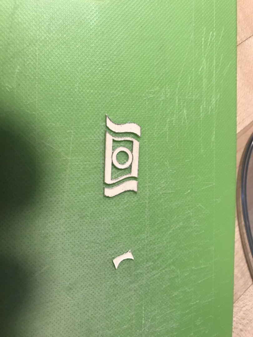
Next, I could use the inner pedestal patterns to demarcate the central raised panel, for planking. I also traced the outer pedestal profiles, though, to be sure that I liked the layout. I made one last check with old man winter (the widest of the four seasons figures) to make sure that I was happy with this:
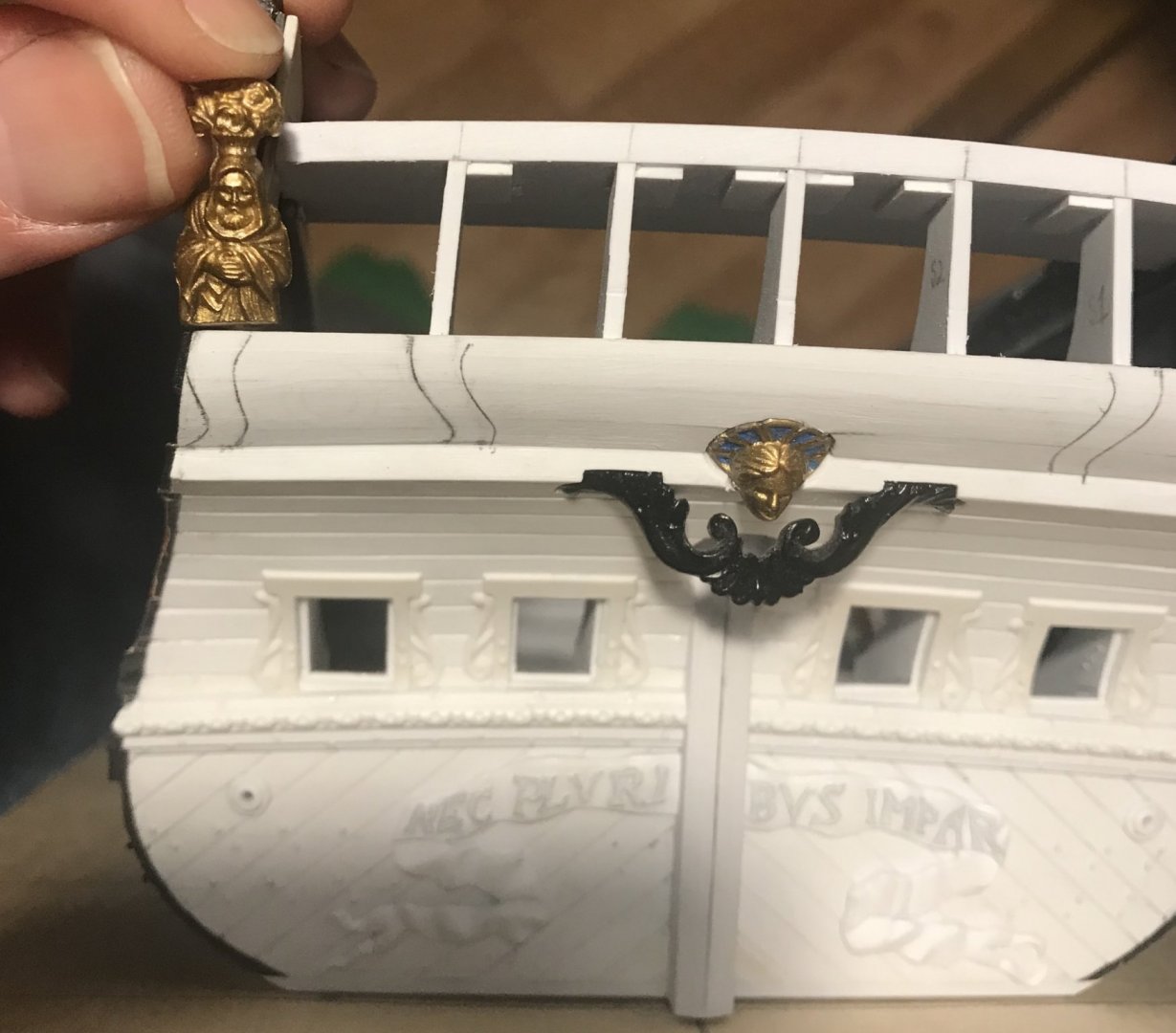
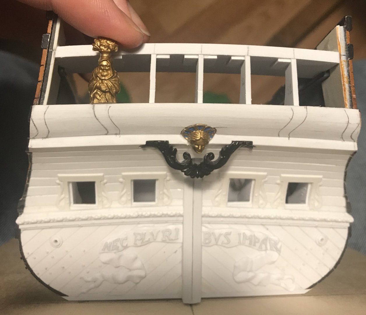
As a side note - the transitional top moulding will run between the Four Seasons figures and the pedestal bases. Both Berain and Tanneron present this as a seamless transition. I, however, do not have enough space to make wider pedestals AND present the more elaborated lambrequin carving. Allowing the top moulding to run between them will nullify their difference in width, as the figures will be fully supported by the moulding. Or, so I think... As I often say, this build is a reconciliation of sources and acompromise in execution.
Finally, I got to planking the next layer. This time, I created a neat radius around the head and crown. I won’t bevel that radius, though, until the final framing layer of moulding, between the inner pedestals, is applied. I nipped the outboard profile of this second planking just a little past my lines; that way I can trim everything flush with the pedestal appliqués, after they are applied.
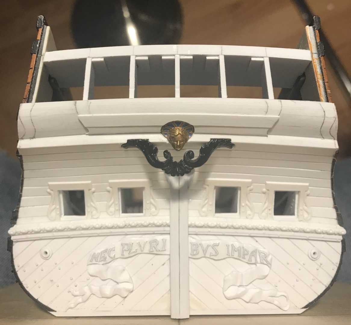
One of the trickier things to keep in mind is that the bottom course, of this second layer, has to be beveled so that it does not interfere with the bottom moulding that helps frame the stern counter, and which I will make, once all the layers and pedestals are in place. The reason for that sequencing is that the top and bottom transitional mouldings have to overhang everything in-between, and I don’t want to guess where all of that may end up. The port side course was beveled flush, after being set in place. The starboard course has only been pre-beveled, so far.
One last consideration is that the counter profile actually extends beyond the tumblehome profile of the stern:
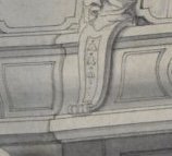
I’m not 100% sure how I will resolve this, just yet, but my inclination is to leave an overhang on the outboard paneling layer (with the circle, and to which the outboard pedestals are mounted, and allow the counter level of the quarter gallery to butt up behind it. This will create the small step that seems to be implied in Berain’s drawing.
So, that’s where things stand, so far. I hope all is well with you all, and thank you for looking in.

This is a challenging thing to approximate onto the Heller architecture. My first break in drawing came after much erasing and re-drawing, and I still wasn’t happy with the result:

I liked the in-board pedestal shape, but I didn’t like the relationship of rake, relative to the outboard pedestal. I also wasn’t quite sure that the circle was the right diameter.
After allowing it to sit for a few days, I came to a realization about Berain’s drawing. Although he does indicate balcony overhangs with shadowing, the drawing is, otherwise, presented as thoroughly one-dimensional, without any foreshortening of perspective for the rake of the stern.
In other words, in order to arrive at a closer impression of what he drew, one must design with the more likely vantage point in mind; as though you were looking at it straight-on, but from a level plane or above.
After much re-drawing, here is how the shapes change when viewed from below:

And then, above:

Now, the layout looked right to me, or at least as close to right as the Heller architecture will allow.
Once I was sure that I liked my shapes, I double stuck a scrap of vellum to just beneath the crease of the stern counter. I, then used my finger nail to sharpen that crease into the vellum.
Then, very carefully, I mapped the reverse curves and paneling onto the vellum with a series of dots that were close enough to accurately fair them, once the paper was removed.
After glue-sticking the paper to a scrap of oaktag, I faired and darkened all of my lines, and finally cut out the three main elements with a sharp matte-knife:

It may appear that the top reveal above the panel is too large, however, there will be a small cove moulding beneath the overhang of the top transitional moulding, and this will balance out the weight of the reveals. As for the bottom reveal, the aforementioned foreshortening of perspective takes care of that issue.

Next, I could use the inner pedestal patterns to demarcate the central raised panel, for planking. I also traced the outer pedestal profiles, though, to be sure that I liked the layout. I made one last check with old man winter (the widest of the four seasons figures) to make sure that I was happy with this:


As a side note - the transitional top moulding will run between the Four Seasons figures and the pedestal bases. Both Berain and Tanneron present this as a seamless transition. I, however, do not have enough space to make wider pedestals AND present the more elaborated lambrequin carving. Allowing the top moulding to run between them will nullify their difference in width, as the figures will be fully supported by the moulding. Or, so I think... As I often say, this build is a reconciliation of sources and acompromise in execution.
Finally, I got to planking the next layer. This time, I created a neat radius around the head and crown. I won’t bevel that radius, though, until the final framing layer of moulding, between the inner pedestals, is applied. I nipped the outboard profile of this second planking just a little past my lines; that way I can trim everything flush with the pedestal appliqués, after they are applied.

One of the trickier things to keep in mind is that the bottom course, of this second layer, has to be beveled so that it does not interfere with the bottom moulding that helps frame the stern counter, and which I will make, once all the layers and pedestals are in place. The reason for that sequencing is that the top and bottom transitional mouldings have to overhang everything in-between, and I don’t want to guess where all of that may end up. The port side course was beveled flush, after being set in place. The starboard course has only been pre-beveled, so far.
One last consideration is that the counter profile actually extends beyond the tumblehome profile of the stern:

I’m not 100% sure how I will resolve this, just yet, but my inclination is to leave an overhang on the outboard paneling layer (with the circle, and to which the outboard pedestals are mounted, and allow the counter level of the quarter gallery to butt up behind it. This will create the small step that seems to be implied in Berain’s drawing.
So, that’s where things stand, so far. I hope all is well with you all, and thank you for looking in.
Last edited:
All I can say is "WOW!!!"
What are you using to make this stuff? I mean do you have any 3D machine or just some plastic sheets? I built this ship as it was in kit, but I can not stop to admire your work. You are building completely new model out of that kit. It is truly amazing. I'm putting my invisible hat down in front of you. Again the experience and knoladge is out of my reach and I can only sit and admire.Designing of these reverse-curve pedestals and the paneling, in-between, has been giving me fits. As a reminder of Berain’s layout:
This is a challenging thing to approximate onto the Heller architecture. My first break in drawing came after much erasing and re-drawing, and I still wasn’t happy with the result:
I liked the in-board pedestal shape, but I didn’t like the relationship of rake, relative to the outboard pedestal. I also wasn’t quite sure that the circle was the right diameter.
After allowing it to sit for a few days, I came to a realization about Berain’s drawing. Although he does indicate balcony overhangs with shadowing, the drawing is, otherwise, presented as thoroughly one-dimensional, without any foreshortening of perspective for the rake of the stern.
In other words, in order to arrive at a closer impression of what he drew, one must design with the more likely vantage point in mind; as though you were looking at it straight-on, but from a level plane or above.
After much re-drawing, here is how the shapes change when viewed from below:
And then, above:
Now, the layout looked right to me, or at least as close to right as the Heller architecture will allow.
Once I was sure that I liked my shapes, I double stuck a scrap of vellum to just beneath the crease of the stern counter. I, then used my finger nail to sharpen that crease into the vellum.
Then, very carefully, I mapped the reverse curves and paneling onto the vellum with a series of dots that were close enough to accurately fair them, once the paper was removed.
After glue-sticking the paper to a scrap of oaktag, I faired and darkened all of my lines, and finally cut out the three main elements with a sharp matte-knife:
It may appear that the top reveal above the panel is too large, however, there will be a small cove moulding beneath the overhang of the top transitional moulding, and this will balance out the weight of the reveals. As for the bottom reveal, the aforementioned foreshortening of perspective takes care of that issue.
Next, I could use the inner pedestal patterns to demarcate the central raised panel, for planking. I also traced the outer pedestal profiles, though, to be sure that I liked the layout. I made one last check with old man winter (the widest of the four seasons figures) to make sure that I was happy with this:
As a side note - the transitional top moulding will run between the Four Seasons figures and the pedestal bases. Both Berain and Tanneron present this as a seamless transition. I, however, do not have enough space to make wider pedestals AND present the more elaborated lambrequin carving. Allowing the top moulding to run between them will nullify their difference in width, as the figures will be fully supported by the moulding. Or, so I think... As I often say, this build is a reconciliation of sources and acompromise in execution.
Finally, I got to planking the next layer. This time, I created a neat radius around the head and crown. I won’t bevel that radius, though, until the final framing layer of moulding, between the inner pedestals, is applied. I nipped the outboard profile of this second planking just a little past my lines; that way I can trim everything flush with the pedestal appliqués, after they are applied.
One of the trickier things to keep in mind is that the bottom course, of this second layer, has to be beveled so that it does not interfere with the bottom moulding that helps frame the stern counter, and which I will make, once all the layers and pedestals are in place. The reason for that sequencing is that the top and bottom transitional mouldings have to overhang everything in-between, and I don’t want to guess where all of that may end up. The port side course was beveled flush, after being set in place. The starboard course has only been pre-beveled, so far.
One last consideration is that the counter profile actually extends beyond the tumblehome profile of the stern:
I’m not 100% sure how I will resolve this, just yet, but my inclination is to leave an overhang on the outboard paneling layer (with the circle, and to which the outboard pedestals are mounted, and allow the counter level of the quarter gallery to butt up behind it. This will create the small step that seems to be implied in Berain’s drawing.
So, that’s where things stand, so far. I hope all is well with you all, and thank you for looking in.
Thank you very much Thomas, JimJ and Ciciak!
To answer your question Ciciak, I began by attempting to draw the project in its entirety, but was quickly frustrated by my old computer, which could not handle the data files, after a short while.
What I did manage to draw was, ultimately, very helpful for laying out the frieze. I have found, however, that the initial parameters of my original drawing were not accurate enough to be reliable.
These days, I draw sections of the model, as I construct it. This way I can measure reliable references for the layout of the ornamental works that require close tolerances for them to work on the actual model.
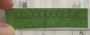
Sometimes, it’s just as simple as making a masking tape template, taken directly from the model, as I did here for the layout of the lambrequin carving:
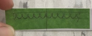
Drawing something like this onto masking tape is a little difficult, but it will be easy to refine the shapes with needle files, after I have scribed through the tape, into the styrene sheet.
My material is mostly white styrene sheet and pre-formed styrene shapes for mouldings, and such. I make mould masters for resin casting for anything that I need a lot of.
I very much enjoy the process and challenge of reverse engineering the kit, and am motivated by the certainty that it will look quite a bit different from any Heller Soleil Royal that I have ever seen. None of this will be a perfect or exact realization of Jean Berain’s designs, but it will be a very reasonable facsimile.
Thank you for looking in! I am very glad that this project interests you.
To answer your question Ciciak, I began by attempting to draw the project in its entirety, but was quickly frustrated by my old computer, which could not handle the data files, after a short while.
What I did manage to draw was, ultimately, very helpful for laying out the frieze. I have found, however, that the initial parameters of my original drawing were not accurate enough to be reliable.
These days, I draw sections of the model, as I construct it. This way I can measure reliable references for the layout of the ornamental works that require close tolerances for them to work on the actual model.
Sometimes, it’s just as simple as making a masking tape template, taken directly from the model, as I did here for the layout of the lambrequin carving:

Drawing something like this onto masking tape is a little difficult, but it will be easy to refine the shapes with needle files, after I have scribed through the tape, into the styrene sheet.
My material is mostly white styrene sheet and pre-formed styrene shapes for mouldings, and such. I make mould masters for resin casting for anything that I need a lot of.
I very much enjoy the process and challenge of reverse engineering the kit, and am motivated by the certainty that it will look quite a bit different from any Heller Soleil Royal that I have ever seen. None of this will be a perfect or exact realization of Jean Berain’s designs, but it will be a very reasonable facsimile.
Thank you for looking in! I am very glad that this project interests you.
I have also wondered how you do this. I am so sick and tired of building kits and then finding them and their instructions lacking in quality and detail that I am on the verge of giving over kits totally. What you have done is quite awesome. Could you elaborate a little more on the styrene sheet and shaping process. I imagine the styrene is not sturdy enough for the actual part? (maybe it is) Is everything cast into resin.? If not all resin, is there any something to coat the styrene to reinforce for strength?
All I can saw is awesome.!!
All I can saw is awesome.!!
After looking more closely, I can now see the difference between the styrene sheets and resin castings. When you reinforced the transom frame work, that all looks like a more solid material. Was that also styrene? And the planking on the stern.
Hi Ken!
Actually the resin castings are strictly ornamental. Mostly, you see these castings on the upper bulwarks. The thinner those are, the more fragile they tend to be, and the bond to the styrene base is strictly mechanical, so I always sand the backs of these ornaments with coarse grit.
Everything that’s white on the lower transom is made from thicknesses of styrene sheet, ranging from a heavy 1/64” on up to a heavy 1/32” and a heavy 1/16”. Forgive me, but I have not memorized the exact decimal equivalents of the different sheet stock.
What happens, as the build progresses, is that you develop a more rigid construction as layers of material are applied and glued to each other. At this point, I’m fairly certain that I could drop this thing on the floor, from the table, and incur only superficial damage - and there have been a few close calls, there

The beauty of the styrene sheet and the profiled styrene extrusions is that they are extremely supple and not brittle at all. The thin sheet can be easily worked in your hands, or on the edge of a table to produce gentle curves that conform nicely with the stern counter, for example.
That was the case for this thin moulding that runs between the inner pedestals, as well as the pedestals, themselves (which are made of a base layer and a thinner raised lip layer):
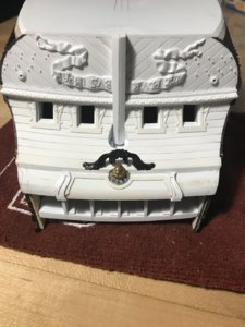
For one-off carvings, like the lambrequin carving that sits just above this moulding, I’ll use styrene sheet - in this case, heavy 1/32”.
As I would for any full-size wood carving. I make a full-size pattern; draw my layout directly onto the blank; scribe through my lines into the blank; remove tape; darken lines with graphite. After that it’s just a process of stock removal with drill bits (especially where I need to create tight radiuses), chisels, files, and then finer carving tools.
Here’s the lambrequin in process:
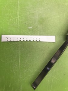
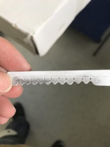
On the right, these “petals” of the lambrequin are pretty close to shape, and now, I have much less material to slice away, from between the petals, than if I had tried to clear that waste before shaping the petals.
Once I have the outline of the thing established, I come back and sculpt the surface of the petals, just as I would with any full-size carving. The plastic really is butter to carve, though. The lack of alternating wood grain to consider, makes the carving process much more enjoyable, IMO.
And that is basically the process; overandoverandoverandover
... until you start to get pretty good at it.
Actually the resin castings are strictly ornamental. Mostly, you see these castings on the upper bulwarks. The thinner those are, the more fragile they tend to be, and the bond to the styrene base is strictly mechanical, so I always sand the backs of these ornaments with coarse grit.
Everything that’s white on the lower transom is made from thicknesses of styrene sheet, ranging from a heavy 1/64” on up to a heavy 1/32” and a heavy 1/16”. Forgive me, but I have not memorized the exact decimal equivalents of the different sheet stock.
What happens, as the build progresses, is that you develop a more rigid construction as layers of material are applied and glued to each other. At this point, I’m fairly certain that I could drop this thing on the floor, from the table, and incur only superficial damage - and there have been a few close calls, there
The beauty of the styrene sheet and the profiled styrene extrusions is that they are extremely supple and not brittle at all. The thin sheet can be easily worked in your hands, or on the edge of a table to produce gentle curves that conform nicely with the stern counter, for example.
That was the case for this thin moulding that runs between the inner pedestals, as well as the pedestals, themselves (which are made of a base layer and a thinner raised lip layer):

For one-off carvings, like the lambrequin carving that sits just above this moulding, I’ll use styrene sheet - in this case, heavy 1/32”.
As I would for any full-size wood carving. I make a full-size pattern; draw my layout directly onto the blank; scribe through my lines into the blank; remove tape; darken lines with graphite. After that it’s just a process of stock removal with drill bits (especially where I need to create tight radiuses), chisels, files, and then finer carving tools.
Here’s the lambrequin in process:


On the right, these “petals” of the lambrequin are pretty close to shape, and now, I have much less material to slice away, from between the petals, than if I had tried to clear that waste before shaping the petals.
Once I have the outline of the thing established, I come back and sculpt the surface of the petals, just as I would with any full-size carving. The plastic really is butter to carve, though. The lack of alternating wood grain to consider, makes the carving process much more enjoyable, IMO.
And that is basically the process; overandoverandoverandover
... until you start to get pretty good at it.
Last edited:
I think that the essential thing is to spend most of your time, with each new element, sussing out the correct shape and proportions of the thing. If those aren’t good, from the outset, it really doesn’t matter how good your carving skills are - the element, no matter what it is, will stick out and detract from the finished model.
I would like to thank you so much for sharing what you have shown here. I will definately be heading to the local hobby shop looking for the styrene sheets and in the future duplicating materials.... Following your build with great interest. Where do you get these styrene sheets? The character in gold, is that a resin reproduction along with the facial figure and the wings on the lower transom... did you also carve those?
Thank you
Here in New York, we still have at least one hobby shop that caters to ship modelers - Jan’s Hobby. The proprietress is an elderly French woman - with vivid recollections of the Nazi occupation, as well as “huffers” who compelled her to stop carrying solvents - who will be your best friend, if you pay with CASH!
From her, I bought a packet of PLASTRUCT .030 styrene sheet. This is the most useful scantling. I also buy a ton of plastic strip and extrusion from her because she has it, and she’s local and this sort of place is a dying breed.
I like Canal Plastic on Canal street because I can get larger sheets of white styrene in smaller and bigger scantlings up to an 1/8”. All of this, however, can be purchased on-line. They won’t be in business much longer, as that entire stretch is being torn down and re-developed; where have you gone, Pearl Paint?!!!!
The off-color ornaments - partially the partially painted gold and black plastic - are actually part of the stock kit. What is unique about what I am doing, here, is that I am finding ways to re-cycle the stock kit ornamentation wherever possible. I have doubles of most of the stern ornamentation - many thanks forever to Henry in Boston - and I use these extras for creative plastic surgery.
Just wait until you see how I am going to operate on the Four Seasons figures so that they extend out beyond the false balcony of the stern counter. I think my idea will work, and that it will be un-detectable, and that it will save me a lot of time - as opposed to carving them from scratch
More to come. As ever - thank you for taking an interest. It is much appreciated!
I googled poly sheets and the local hobby lobby has various sizes. Looking forward to how you do the "old man winter" scenario. Will definately try my hand at this. I used to be a dental technician creating crowns, bridges and dentures. Plus uses in gold plating, duplicating materials, casting etc. This will definately been a plus in creating these things.
I am currently just starting the Mamoli victory 1/90. (8th build). Think I'm going to bash the heck out of it. The quality of the parts are just terrible. Thanks
Ken..
I am currently just starting the Mamoli victory 1/90. (8th build). Think I'm going to bash the heck out of it. The quality of the parts are just terrible. Thanks
Ken..


