Staghound...Extreme clipper 1850 by rwiederrich 1/96

Many thanks for this small but very interesting tutorial - clever idea and smart executed
Thanks for the fine comments. I needed a bunch, and I wanted to make them the easiest, yet the most effective way. The first one took me about 30 minutes to make...including the time spent thinking the thing up. After that, I got production time down to about 10 minutes a piece.
I hope others will use this method. Mine are as small as practical...but they can easily be sized up.

Rob
 
Outstanding. Thanks for the tutorial! Okay
No....thank you... Pete.:D I'm glad others even find the process doable. Over the years...I've seen others, make their gin blocks by soldering formed bands together...then solder on an eye. Trying all the while not to unsolder the previous solder job. It simply made sense to me to just take a tube....flatten it to form the ovoidal shape....then simply cut out the pieces not needed. There you go...the horizontal banding and the vertical band...all in one piece. Just solder the eye on and its formed. Adding the sheeve is not a real problem...just drill some holes, pin in your sheeve and there you go. Well....not exactly...:cool:....that has its own issues.... But the cross tree body is easy to make.

Some cutting, soldering, drilling skills..... and there you go.

Rob(My minds a whir of deep cosmic transient thought)
 
Just fair warning....I will be on holiday for a week, celebrating my 40th anniversary....so I won't be posting any work updates. I'll be monitoring, but not adding any construction content.
I just wanted to say to everyone who's been following this log....thank you and thanks for your interest and support. I really appreciate it a lot.
I'm really waiting on the bulkheads...cuz as soon as I get those bad boyz...we're off to the races.:cool:

Rob
 
Happy anniversary Rob!

Bill
Rob, Vlad, Luis, Peter & two Bills,
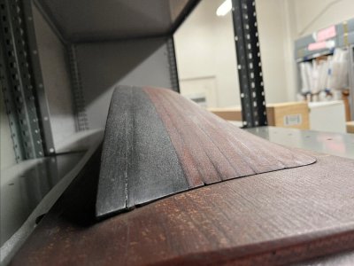
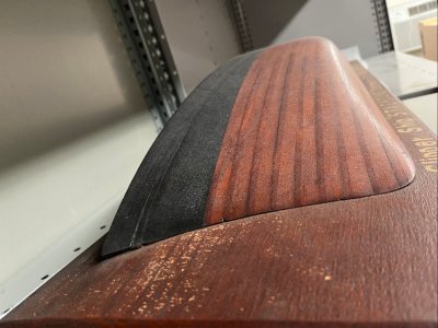
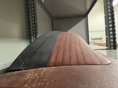
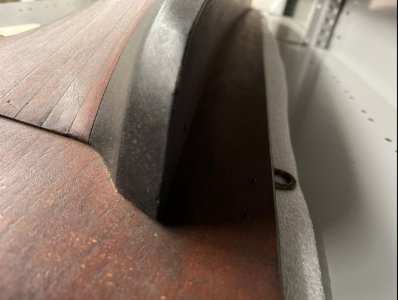
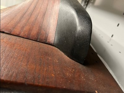
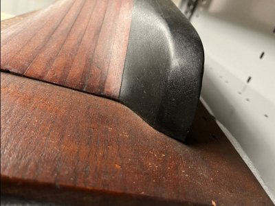
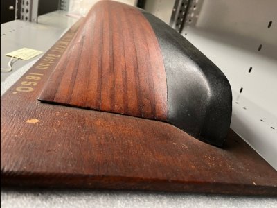
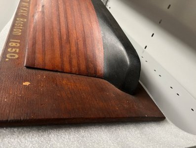
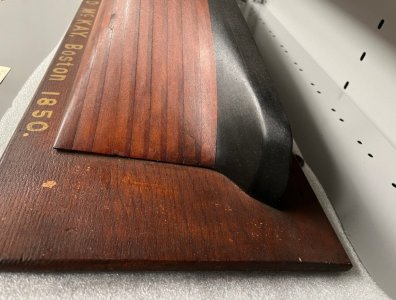
I just received 9 more images of the Cornelius McKay Stag Hound model from Lori Fidler, Associate Director of Collections, The Old State House Museum, Boston. MA. She was able to get bow and stern photos but no others due to her limited access. What's very noticeable is her radical 40" deadrise at half-hull. No other clipper built by Donald McKay had such a deeply "v"d hull. His next clipper Flying Cloud flattened this out 10 degrees to 30" at half-hull. Gradually McKay continued to have flatter hulls until his last medium clipper Glory of the Seas which had a mere 8" at half-hull.

20240927_083827.jpg

20240927_083603.jpg

20240927_083033.jpg

20240927_084343.jpg

20240927_084418.jpg

20240927_084418.jpg

20240927_084721.jpg

20240927_084750.jpg

20240927_084815.jpg
 
Last edited:
Of course less deadrise would increase cargo capacity. Also, in his Search For Speed Under Sail, Howard Chapelle makes the case that voyage records made by many of the clippers were a result of their their ability to carry a heavy press of sail as it was of hull form. Sail carrying ability is affected by initial stability (Metacentric height). All else being the same, the flatter floored reduced deadrise hull form would increase Metacentric height and allow more sail to be carried in strong winds.
 
Of course less deadrise would increase cargo capacity. Also, in his Search For Speed Under Sail, Howard Chapelle makes the case that voyage records made by many of the clippers were a result of their their ability to carry a heavy press of sail as it was of hull form. Sail carrying ability is affected by initial stability (Metacentric height). All else being the same, the flatter floored reduced deadrise hull form would increase Metacentric height and allow more sail to be carried in strong winds.
Roger,
One of the tougher inaccurate myths we had to dispel in our research efforts to get an accurate Glory of the Seas reconstruction was the idea that a medium clipper wasn't a sleek hull. Reality was that, while she had far greater carrying capacity, due to her enormous hull, she was still designed with very sharp hydrodynamic features fore and aft. She was originally launched with a towering rig. Above deck, her lofty manmast towered nearly 200 feet and she carried a full suit of stuns'ls on every mast. McKay's first clipper Stag Hound, at time of launch in 1850 would have been dwarfed in comparison. Her mainmast height was 166 feet from her deck!
 
All of these ships were designed prior to knowledge of William Froude’s work to understand the hydrodynamics of ship hull resistance. In fact there were some widely publicized theories at that time that were completely wrong; Russel’s Waveline theory, a case in point. Design of these vessels was, therefore largely intuitive. Chapelle also makes the point that successful Clipper Ship designers adapted low deadrise Packet Ship hull forms instead of the high deadrise Baltimore Clipper designs.

Experimental tank testing using Froude’s system of separating frictional and wave making resistance has been the standard for designing ship hulls into the present day. There has been progress to utilize finite element analysis techniques for making hydrodynamic calculations but tank testing is by no means obsolete.

Froude also discovered a “brick wall.” When a ship reached a speed equal to somewhere between 1 and 1.5 times the square root of its waterline length it became trapped by the wave train created by the hull. Tweaking hull lines might move the multiplier slightly but top speed was dominated by waterline length. A 250 ft ship, therefore, had a higher possible top speed than a 200ft vessel. Glory Of The Seas by virtue of her huge size could reach higher speeds than smaller Clippers provided there was wind to push her and a rig to handle it. This also casts some doubt on paintings showing Clippers in heavy air with all sails set. At this point, the ship would just be pushing water, and at risk of broaching.

Of course these ships also had to deal with light air during their voyages. In this case hull resistance would be dominated by frictional resistance which is dependent on hull area x a drag factor squared. A sleek hull would be important to reduce the drag factor. Nowhere near as dramatic as a Clipper Crashing through heavy seas with all sails set but just as important to making fast voyages.

Roger
 
All of these ships were designed prior to knowledge of William Froude’s work to understand the hydrodynamics of ship hull resistance. In fact there were some widely publicized theories at that time that were completely wrong; Russel’s Waveline theory, a case in point. Design of these vessels was, therefore largely intuitive. Chapelle also makes the point that successful Clipper Ship designers adapted low deadrise Packet Ship hull forms instead of the high deadrise Baltimore Clipper designs.

Experimental tank testing using Froude’s system of separating frictional and wave making resistance has been the standard for designing ship hulls into the present day. There has been progress to utilize finite element analysis techniques for making hydrodynamic calculations but tank testing is by no means obsolete.

Froude also discovered a “brick wall.” When a ship reached a speed equal to somewhere between 1 and 1.5 times the square root of its waterline length it became trapped by the wave train created by the hull. Tweaking hull lines might move the multiplier slightly but top speed was dominated by waterline length. A 250 ft ship, therefore, had a higher possible top speed than a 200ft vessel. Glory Of The Seas by virtue of her huge size could reach higher speeds than smaller Clippers provided there was wind to push her and a rig to handle it. This also casts some doubt on paintings showing Clippers in heavy air with all sails set. At this point, the ship would just be pushing water, and at risk of broaching.

Of course these ships also had to deal with light air during their voyages. In this case hull resistance would be dominated by frictional resistance which is dependent on hull area x a drag factor squared. A sleek hull would be important to reduce the drag factor. Nowhere near as dramatic as a Clipper Crashing through heavy seas with all sails set but just as important to making fast voyages.

Roger
Roger,
Would you be surprised to learn that I never heard of Froude before your dissertaion just now? Fascinating description of the science behind effective hydrodynamic architectural design. I did a fascinating ratio study of McKay's clippers in order to determine how Glory of the Seas medium clipper compared to his other extreme clippers. I compared two factors:
(1) keel length divided by main deck length (stem to sternpost)
(2) keel length divided by (knightheads to taffrail) also called length over all.
What surprised me was based on these ratios, the medium clipper had one of the fastest ratios than many others. This helped us clear up the misconception about medium clippers being slow.
 
Froude also discovered a “brick wall.”

That's fascinating. It is analogous to the 'sound barrier' and the developments in aerodynamics required to overcome the effects of shock waves - different waves but waves all the same. There's always something new to learn and I think I need a book on these subjects. Do you have any recommendations.
 
Following these fora is a source of serious scientific information that directly impact how we build and display our models!
I just recently finished reading "Flying Cloud and the Woman Who Guided Her" in which the author describes the settings and conditions under which all sails, and in particular the studding sails, were set. I gathered from the book that the information given was derived from the writings by Captain Creesy in the ship's log.
 
I looked through my books. Naval Architecture for Non Naval Architects by Harry Benford is a well written tour through the factors involved in ship design. Benford was a Professor in the Naval Architecture and Marine Engineering at the University of Michigan. He was an expert in the economics of the shipping industry. I took a couple of courses from him. He was an excellent instructor with a quick wit. He could quickly sketch the outline of a pig on the blackboard to illustrate the principle of a ship hogging.

To learn a little more about the Brick Wall that I described look up Hull Speed on the internet. You’ll find a number of articles including one claiming that it’s a myth. Actually this author just explains how boats with very narrow hull go faster by reducing their wave trains. The overall principal still stands.
 
Last edited:
Following these fora is a source of serious scientific information that directly impact how we build and display our models!
I just recently finished reading "Flying Cloud and the Woman Who Guided Her" in which the author describes the settings and conditions under which all sails, and in particular the studding sails, were set. I gathered from the book that the information given was derived from the writings by Captain Creesy in the ship's log.
Peter,
It's been probably a decade since I read that fascinating book. If memory serves, the author credited the Flying Cloud log for his reconstruction of their journey. He might even have a list of sources at the back of the book too.
 
I looked through my books. Naval Architecture for Non Naval Architects by Harry Benford is a well written tour through the factors involved in ship design. Benford was a Professor in the Naval Architecture and Marine Engineering at the University of Michigan. He was an expert in the economics of the shipping industry. I took a couple of courses from him. He was an excellent instructor with a quick wit. He could quickly sketch the outline of a pig on the blackboard to illustrate the principle of a ship hogging.

To learn a little more about the Brick Wall that I described look up Hull Speed on the internet. You’ll find a number of articles including the claim that it’s a myth. Actually this author just explains how boats with very narrow hull go faster by reducing their wave trains. The overall principal still stands.
Roger,
Do you think that hydrofoils are an attempt to break this hydrodynamic speed barrier?
 
Back
Top