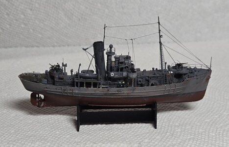
T227 Sir Gareth, round table class trawler, 1:48 scale, 3D print and scratch build [COMPLETED BUILD]

Joined
Jul 18, 2024
Messages
268
Points
238

I already started with her a few weeks ago, so I'll have to summarise what's what up till now.

First: this is a steep learning curve for me. I started designing in CAD (Fusion) AND started 3D printing AND started scratch building. Oh well. I have some experience in reaching unattainable goals ... worst that can happen is that I learn.

Second: I will build the ship according to John Lambert plans, photos and whatever I could find online. BUT I will deviate where I think it will serve the model and the goal: having fun designing and building her. I am less of a "pixel peeper" and more of a "that looks good" person.

So, about T227. She's one of the class with a deck house and she's one of the trawlers painted mostly in 507a: dark grey. After WW2 she was sold and converted to a true trawler, namen "Milford Star". Guess what, I built that one. So there is a logic in my choice for Sir Gareth.

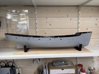
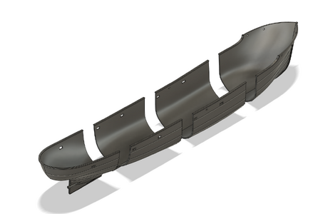
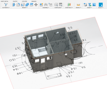
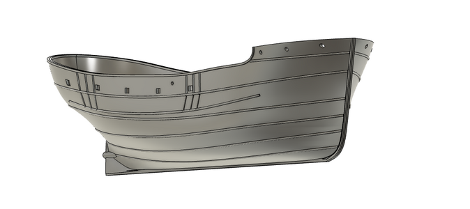
The model: I wanted to really start from scratch, so started designing the hull in CAD. That was fun ... I never thought about hulls ... they are kind of 4D shaped ... warped ... But after a dozen mishaps and mistrials, I succeeded in getting something I could print.

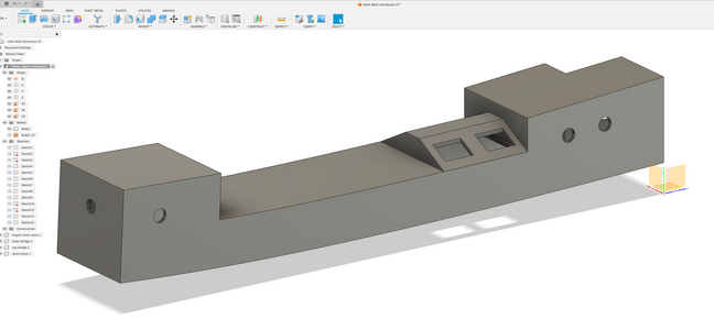
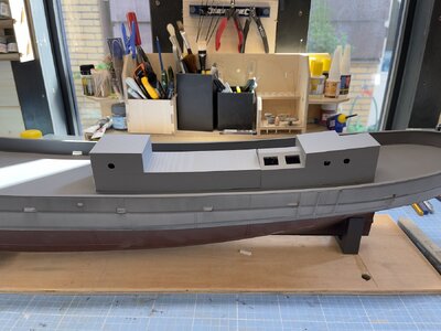
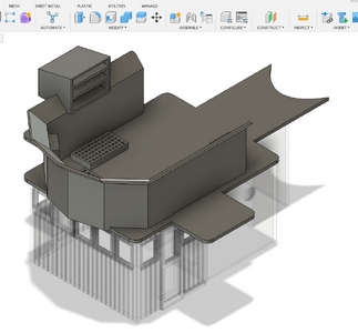
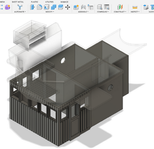
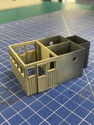
After that I created the rough structural objects of the model: deck house, main upper structure, etc. This all in FDM (filament). Later on I'll do the detailed parts in resin. And I'm sure I'll revert to good old fashioned brass wire, "plastic strip", etc. where appropriate. It's no b****y use trying to be smart in 3D when a piece of rod and a sharp knife can do the job in half the time.

So here we are, with a rough setup and a looong time ahead detailing.
Screenshot 2024-07-01 at 17.49.47.png

tempImageIIsRag.jpgScreenshot 2024-07-13 at 15.41.27.pngtempImageMe0D7z.jpg
 
Looking very good - and a very interesting vessel, so I will follow your log with big interest
Many Thanks for starting this log

Is the hull printed? Do you have such aprinter to do something big like this?
 
As I’d already done a lot of preparation before setting up this log, it looks like I’m running. No worries, you’re just catching up.

I worked on the bridge and compass bridge for a couple of days. First draft prints looked OK.

Here are some images of the design phase.

Screenshot 2024-07-18 at 16.23.17.png

Screenshot 2024-07-19 at 15.42.43.png

Screenshot 2024-07-19 at 15.43.07.png
 
I printed the compass bridge in resin and fdm, but both were lacking. Resin turned out to lose details around edges and in fdm the supports would not come loose. So after a night's sleep, decided to simplify the process: the base structure, without cabinet and such, will be printed in fdm. And I will do the detailing in resin. That fits with my overall plan regarding detailing anyway.

The main bridge came out nicely from the fdm printer. I already put some primer on: light coloured will be "wood". I'll have to do some sanding and such to make it pretty, but that's fdm for you.

Note: the overall colour of all steel parts will be 507A, dark grey. I know there are a lot of Round Table trawlers in camouflage, but only 2 out of 8 had that scheme. T227 Sir Gareth was "home fleet" and dark grey, without pennant.


IMG_5021.jpeg
 
A very interesting project. Building the model in the manner you have chosen certainly requires specialized knowledge
and experience. Thanks for sharing. I'll be following along with great interest.
The more I review your work, the more I wonder if there should be a separate category for models that are totally printed.
The skills required for a printed project vs the classic scratch built are very different. What you are doing is much more of a challenge
then just replacing some kit parts with aftermarket printed parts.
Just a thought
Cheers, Harley
 
Harley g’day.

First: the “specialised knowledge” is more or less developing as I go. Not to bluff, but six months ago I had nil experience. So do get your own time in! It’s just a question of starting. There’s tons of info on YouTube and whatever.

After this 100% 3D work I’ll more or less revert to more traditional building. So not sure if we’d need a special chapter for that. But if a mod or whatever it’s called on this forum thinks it’s a good idea, I’m happy to move the lot to that place.

Cheers,

Marco
Greetings Marco,
Just to clarify my comment. I, in no way, meant anything derogatory about your Sir Gareth project. I already spend too much time on YouTube. Too much good information.
My Sir Gareth is 1/350.
Regards, Harley

HMS Sir Gareth.jpg
 
As said, I already did some work before I started this topic. And although I am mostly focusing on the grand structures, I wanted to try my hand at some detailed work as well.

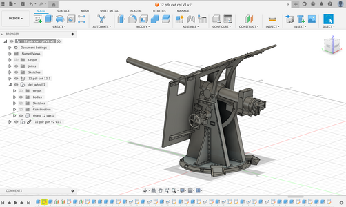
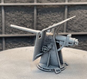
First the 12 pounder gun: there's not a whole lot of information available and even John Lambert had to guess a few things, measuring from one of the only existing (part) 12 pounders. But from his drawings and from some of the photos in the magnificent book "British naval trawlers and drifters in World War 2", I got a fair idea of how to proceed. And I knew that in print, at scale, a lot of "mistakes" would simply disappear.

I started CAD work in Fusion from scratch, flanges first, then gun tube, then details. "Steep learning curve" being an understatement.

At 1:48 scale it fits in your hand. The trick for detailing turned out to design BIG, then scale back to size. The image of the actual model is taken in my paint booth, so still wet from first primer. It is going to be fun to paint the little rods and levers.

Screenshot 2024-06-15 at 16.36.06.png

IMG_4852 (1).jpeg
 
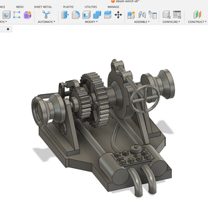
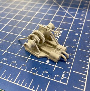
Another important detail is the anchor winch whatchamacallit. Another fine challenge, as even less was available. So I looked at some photos of more or less similar winches and just guessed my way ahead. It helped images of other models (E.G. 'Sir Kay') can be found in abundance. Fun fact: after I had drawn the two gears I found out that Fusion has a plug in enabling drawing them in about 1/10th the time. Oh well. I am not an engineer.

As we speak, the thing is on my resin printer. A first draft showed good promise, but I didn't like too long axles on the outer warping drums. So I shortened these. And I had to wing the clutch house, as it would otherwise become too flimsy. And of course I didn't fully understand the technical concept. But again, most if not all mistakes will disappear at 1:48 scale.

It needs cleaning up, too. The little dots come from the supports.

Screenshot 2024-07-22 at 13.30.51.png

IMG_5038.jpeg
 
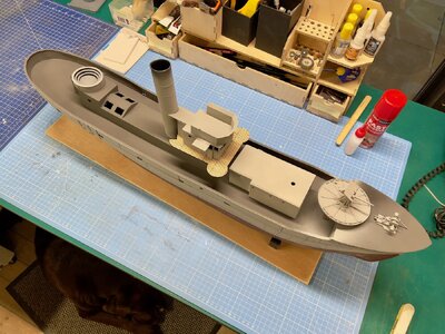
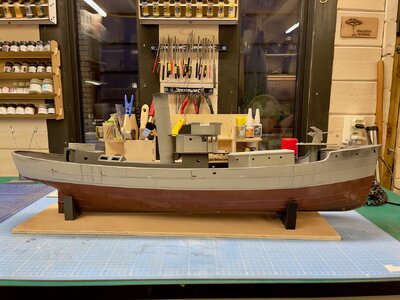
IMG_5042.jpegIMG_5040.jpegThe structural parts, eg bridge, deckhouse, funnel, etc. are done. All rough and requiring lots of attention. In the end I decided to laser cut the bridge deck. This ship simply must have some real planking. And I simply had to put it all together for this first overall shot. No worries, there's no glue applied. It’ll all come off again and will be in my hands for quite some time.

Which means that from now on, I will be taking smaller steps, making slow progress. But it will be fun!
 
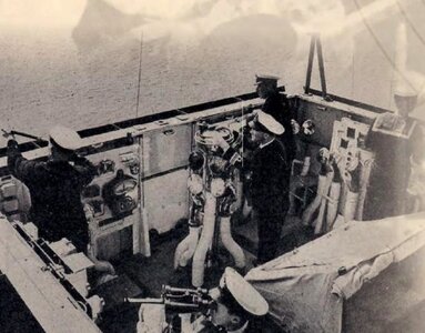
It is all comming togeather really well Marco, I particuarly like how the 12 pound gun turned out. I noticed in some of your graphics that the small navigator 'hutch' on the flying bridge had shelves in it. I am not to sure about this and only put a flat bottom on the one I made. 3D printing is a great way to go particuarly in making pieces that are repeated, mushroom vents for example. When I make such parts by hand there is always a small difference. Chapeau bas JJ..
 
Jack, thanks for reviewing and especially thanks for the 'heads up' about that strange box like contraption. It took a while to understand what it actually is. In my view it is an enclosed weather and light proof 'reading corner' for maps and such. That makes sense on an open bridge. I found an image, albeit vague and of the wrong ship. But it shows the box! It is, as you said, without shelves and has a curtain. See below right bottom corner. On a small bridge you would indeed balance it on a side board.

compass bridge.jpg
 
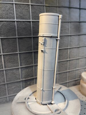
I thought I would slow down. Oh well. It was a good day. Had time to redo the gun platform, now according to Jack’s design (thanks!). But also picked up the smoke stack and added quite some detail. Here it is in a first primer. The light is bad: the stack is much nicer in reality. Actually did a rapid design on the steam whistle. That was fun. I am getting a hang on Fusion.

Will see what else needs to be done tomorrow. Or day after.

IMG_5045.jpeg
 
Hi Marco, I am intrigued, taking your funnel as an example, can you safely drill into the resin to add other components? For example brackets for the main mast. Are you intending to use wood or are you going to print the masts also?
BTW you may well know already but I found the UK's Imperial War Museums web site a great source for photographs, for example; https://www.iwm.org.uk/collections/item/object/205121480 I hope I am being helpful and not a nusance.

All the best Jack..
 
Jack, I really appreciate the support and never take any remarks as a nuisance or in a negative way. My view: if you are only in it for the likes, Facebook is a better place

About the IWM: I was aware, but had forgotten. I actually want to visit the sites sometime this year.

Resin and drilling, masts:
First about resin. There’s a lot of talk about the dangers of sanding and drilling, but that’s with any fine dust. So ventilate and when doing lots of work, wear a mask.

About drilling: yes, that is just like plasticard or other usual model “plastic”. I have no worries about attaching small bits or wires without a lot of tension. But I’m sure I’ll create a back filler if I think there too much force.

The smoke stack is FDM printed with PLA. That is sturdy enough.

Masts … my plan was wooden, but it would be interesting to see if they would hold up in FDM. It would not work in resin, I’m sure. And brackets will work in FDM anyway.

Hmmm … I’ll do some research which filament would be best. I have PLA, PETG, ASA en Polycarbonate available. PC may be the one. Test will tell.

Nice!

I will “cheat” a little anyway, as I bought some brass D shackles, brass portholes with glass, chain and such. Although I could print the portholes … oh well.
 
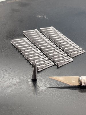
Every modeller will recognise the necessary but really boring chores that pop up once in a while. This is where 3D printing really comes to its own.

40 pieces of 18mm bulwark supports, with rivets and all: 60 minutes from first line on Fusion to a bed full. I'll have to sand them a little, but will do that on the bed. Did a few strokes already, hence the dust.

IMG_5048.jpeg
 
Last edited:
Back
Top