Follow along with the video below to see how to install our site as a web app on your home screen.
Note: This feature may not be available in some browsers.
Ships of Scale has incorportated an extra level of security when you log In. Please follow
on-screen prompts to acknowledge that you are not a robot via a "Check Box" or a "Pictorial Check Box Puzzle". This is needed due
to higher level of AI Activity Security.
The beloved Ships in Scale Magazine is back and charting a new course for 2026!
Discover new skills, new techniques, and new inspirations in every issue.
NOTE THAT OUR NEXT ISSUE WILL BE July/August 2026
Win a Free Custom Engraved Brass Coin!!!
As a way to introduce our brass coins to the community, we will raffle off a free coin during the month
of August. Follow link ABOVE for instructions for entering.
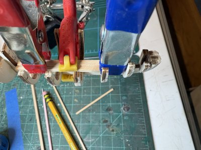
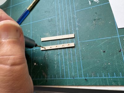
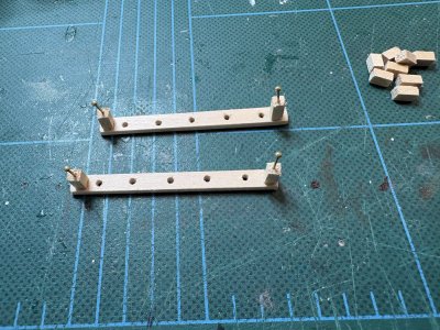
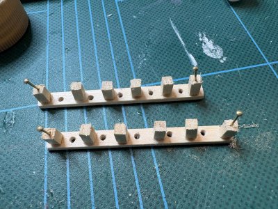
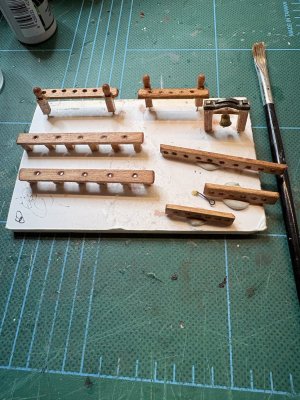
Waiting for things to dry I started on the rails to hold the belaying pins.the information on how to make these is rather sparse. I have to look at the parts list to see what length they want them to be and try to figure out how many holes they want. 2x5mm wood strip is used except one piece where they want 2x6mm. Why? Who knows. Also some small stanchions are labled Q10 on the pictorial instructions but there is no Q10 in the parts list. I believe they mislabeled them Q9. They would have you drill 2mm holes to place the belaying pins in but I found that was too loose. I found 1.8mm holes made for a much better fit. I drilled the holes with my nail drill , after using a bit of math the figure the spacing between holes. I rounded the edges of the strips, but I doubt anyone will see that viewing the completed ship.
3x3mm strip each 6mm long were used as stanchions. The end stanchions are to have pins put in them. They suggested to use the included eyelets. I instead used some of the many nails I did not use to attach the planking. I drilled small holes before putting the nails into the stanchions.
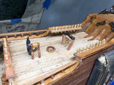
The remaining stanchions were glued into place.
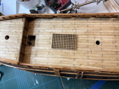
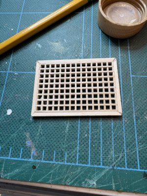
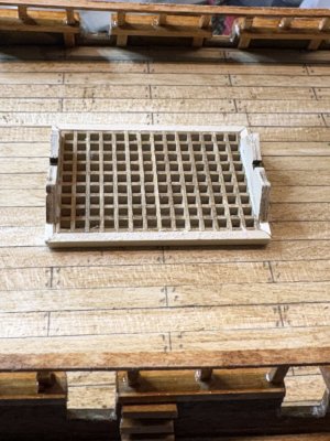
The grating was cut to size to fit over the opening in the hull. The edges of the grating were sanded. The grating was "weathered with the Bitumen of Judea. They would have you now make a 2x2mm strip edge around the grating, but I kind of like the look of it like this. I may leave it as is.
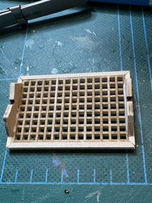
Well forget what I said above about not framing the gratings. Two davits for a boat are supported by the framework. So using some 2x3mm strip I formed a framework around the grating. I cut small mitered joints so it would look neat.
The davits were then glued to the framework. Placing it on the hull it looks good. I will use the Bitumen of Judea to match the colors.
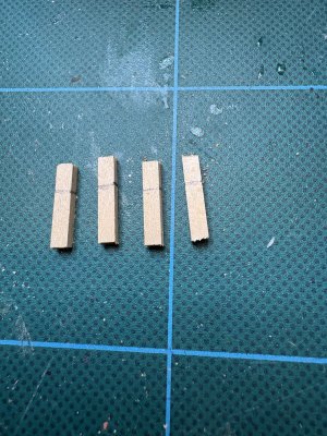
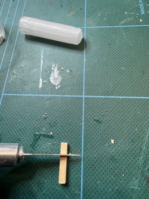
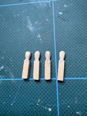
I notched the edges of two of those pin rails to receive a 3x3mm stanchion to hold them up. The stanchions were made of strip cut to size. The tops are supposed to have a decorative head on them. To do that I marked a line 5mm from one end to denote where the base of the decoration would be.
Using an Xacto blade,I then scored the wood fairly deeply along the lines I drew.
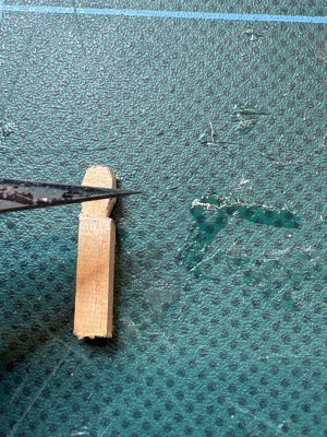
I then repeatedly carved out small wedges of wood on the corners both to the line and the top;
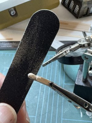
Taking my time, I then did the same thing along the faces of the strips, creating a "neck" along the line. When I was satisfied with the rough shape I finished shaping the piece with sandpaper. I used emery boards as I find them easy to handle. These have 120 grit on one side and 240 grit on the other.
This is the results after a few minutes work.
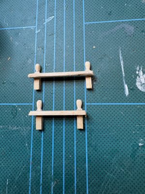
The stanchions were then glued onto the pin rails.
I have spent more than a few minutes looking over the plans for the mast boots. The parts are labeled and looking at the laser cut pieces I could for the life of me not find them. But lo and behold there they were in the box containing the pins, dead eyes, flags etc. The parts list has them as premade not precut! Any way, I attached them to where they belong in the foremast and mizzen mast holes. The piece for the foremast early slid over the wooden dowel that is to become the foremast. The piece for the mizzen mast needed a bit of sanding for it to fit the 6mm dowel that is to be the mizzen mast. They were glued into place with the dowels in position and then the dowels were removed.
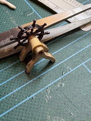
The ships wheel assembly was also assembled. The round "drum" that the steering ropes engage was another premade part in the parts box.
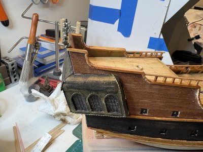
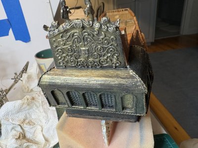
The captains cabin was glued into place. Before that can be attached the metal "decoration" piece had to be placed first since the top of the cabin sits on top of that. The metal piece was secured with CA and the cabin with PVA glue.
Just a quick note. I will be away from this work for about 3 weeks. The good news is that I will b restarting my Bluenose, which I am looking forward to.
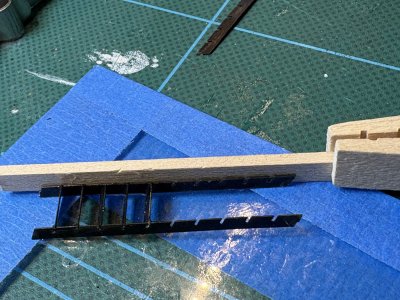
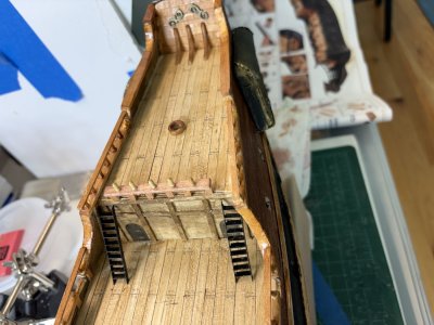
Next up they have you build some of the deck furniture. The ladders are made from PE. I painted the components before assembling them. This cause a little more clean up but it may be easier than painting after the ladder is together. It is also possible to use a sharpie pen to "paint" the pieces. It can be frustrating to assemble such small items. I used a strip of plank to secure one of the sides of the ladder to to assemble it.
Once one rung was on, the other side was secured to the rung. CA was used as the adhesive. Other rungs slid in rapidly.
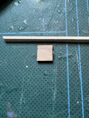
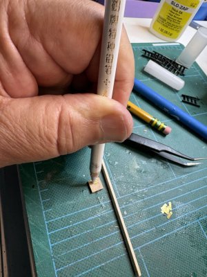
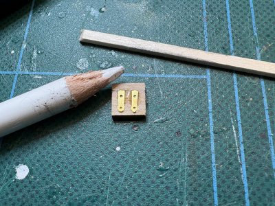
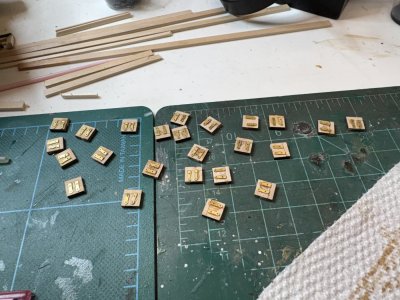
The covers for the gun ports are next. Each cover is glued into the upper part of the gunport. It goes in about 1.5mm. There are 2 PE hinges on top of each cover. Using a piece of scrap, I drew a line about 1.5mm from the edge of the covers to know where to start the PE pieces.
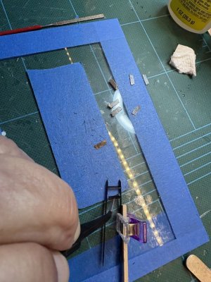
The PE hinges are rather small and of perfect size to fly off a pair of tweezers on their journey to the lost dimension of small model pieces. I have found that using a wax pencil really simplifies the manipulation of these pieces. The hinges were dipped into a drop of CA and affixed into place.
The pin rails and the holder for the ships bell were stained Minwax cherry stain.
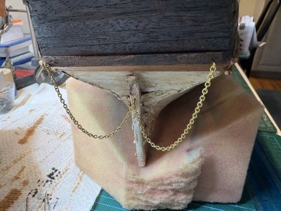
The rudder apparently has a chain to keep it with the ship if it somehow becomes detached. I took 160mm worth of the included chain and saved the rest. Holes were drilled in the appropriate places on the ship hull and the rudder and eyebolts were cut to fit them. The eyelets were opened a bit with a needle nose pliers and the chain links were big enough to allow the eyebolts to slide into them. The eyelets were then closed and the eyebolts were glued to the ship using CA.
A railing was built with spare strip and the stanchions made from cut eyelets. The railing was stained and glued into position.
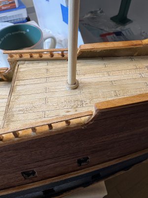
The pin rails and ladders were glued and set into place. The pin rails had pins made out of the leftover nails installed and then positioned. Holes were drilled into the deck and everything set into place with CA.
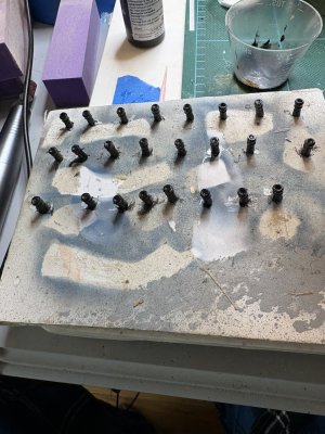
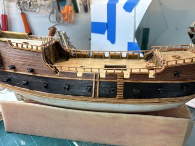
The gunport covers were primed, painted black and installed into the gunports. The cannons and "false" half cannons were prepared. I have to complement Occre on the casting of the cannons and really all their castings. They are exceptionally crisp and free of flash. Nice work on their part! The cannons were washed in dish soap and hot water to get rid of any releasing agent, rinsed and dried. I set them up on a piece of foam board to hold them and primed them and painted them black.
They were then glued onto the piece glued behind the gunports. I was careful not to press them in too hard. I did not want the piece behind the gunport to fall off.
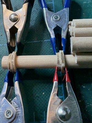
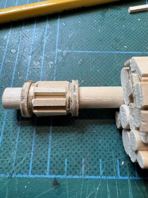
A ships capstan is to be constructed. This capstan surrounds the main mast. I certainly haven't seen such a set up before. Four laser cut rings were used to form the top and base. To make sure they would be concentric, they were glued together using the mast dowel as a "jig" to hold them. The glue was carefully applied and the rings clamped together. They were moved every few minutes to make sure they didn't glue to the dowel.
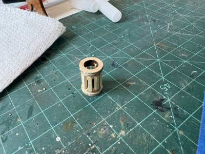
Eight 10mm long 2x2mm strips were then glued to the two rings again making sure the glue did not attach to the dowel.
Once the glue dried the assembly was removed from the dowel.
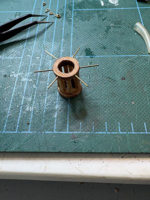
The capstan was stained and 6 0.8mm holes were drilled along the top ring. The ring portions of 6 eyelets were nipped off and the shanks were glued into the holes using CA.
This was again slipped over the dowel to make sure it would still fit.
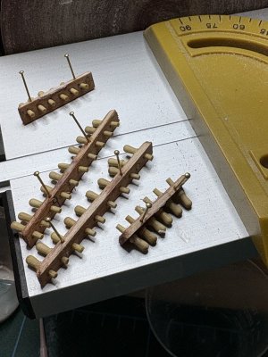
While waiting for the stain to dry on the capstan, I drilled some holes in the pin rails that are to ago on the bulwarks of the ship. Using CA, nails were glued into the holes. These will be cut short and used as pins to reenforce the attachment of the pin rails to the bulwarks.
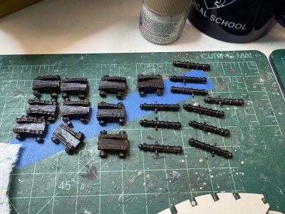
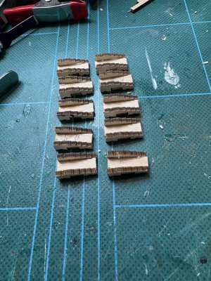
The cannon carriages were assembled from laser cut pieces.
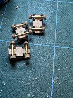
After looking at the laser cut boards I realized that the wheels for the cannons were premade and in the parts container. Axels are made from 15mm lengths of the provided 1.5mm brass rods. The wheels were attached to the axels with CA and the axels mounted onto the carriages with CA.
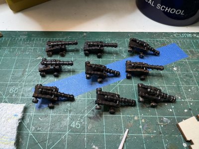
The cannons and the cannon carriages were primed and painted black.
The cannons were then assembled using CA. Most of the cannons were front heavy a small amount and tilt forward. However since they will be glued to the deck it should not really matter.
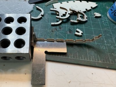
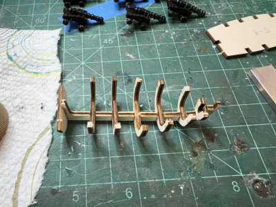
While I was waiting for the paint on the cannons to dry, I started to put together the ships launch. It is a smaller POB model. I used a small square to make sure the frame was set accurately.
The pin rails, ships bell and wheel all had small pins placed. Small 0.8 holes were drilled in the appropriate (I hope) places using my nail drill and the parts secured into place using PVA.
Going a bit out of sequence, I decided to place the floor of the launch before planking. The flooring is 2 x 2mm strip. I did this for 2 reasons, I figured the flooring would help reenforce the frames and both the flooring and the framing will be stained with the included mahogany stain, so why not do both at once.











 .
.