• Win a Free Custom Engraved Brass Coin!!!
    As a way to introduce our brass coins to the community, we will raffle off a free coin during the month of August. Follow link ABOVE for instructions for entering.

The GRACIE S - a Lift Model

Joined
Dec 7, 2022
Messages
89
Points
78

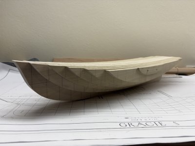
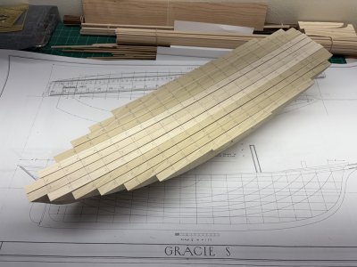
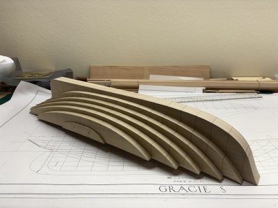
Within this thread I plan on demonstrating how the hull of Gracie S. can be fabricated using a lift technique.

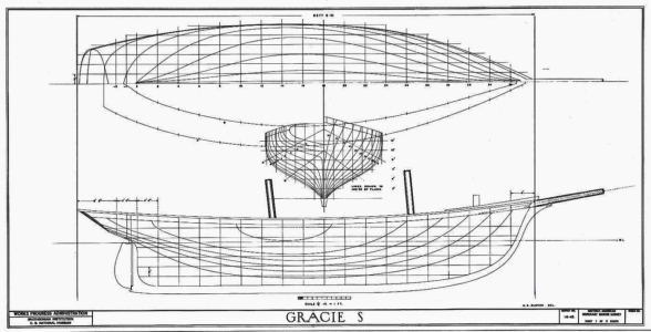
A few days ago Dave Stevens, in the PLANS thread, posted this image of the plans for Gracie S from the Historic American Merchant Marine Survey (HAMMS):
1762717373098.png

If you think of Gracie's hull sitting in a rectangular solid, then the vertical and horizontal lines in the three views above can be aligned with three sets of slices in the rectangular solid. One set of slices cuts the rectangular solid like a loaf of bread - there are 20 such cuts in Gracie's plans. The intersection of Gracie's hull with these cuts gives rise to the body plan seen in the middle of the HAMMS plan above.
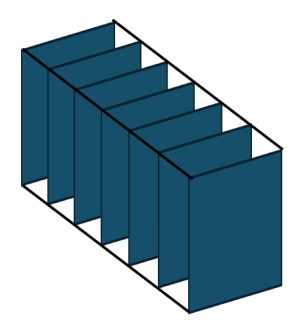
1762717885338.png

A second set of slices is like layers in a cake - there are 7 layers in Gracie's plans. The intersections of Gracie's hull with these cuts give rise to waterlines - the shape of these curves can be viewed on the top drawing in the plan above.
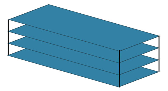
1762718368568.png

A third set of slices can be made as vertical slices from front to back - there are 14 layers in Gracie's plans. The intersection of Gracie's hull with these slices are called buttock lines and can be viewed on the lower drawing of the HAMMS plan.
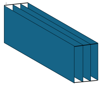
1762718647794.png

Plank on bulkhead (POB) and plank on frame models (POF) rely heavily on the body plan for shaping bulkheads (molds) and/or frames. If one fills in the region between bulkheads / frames a solid hull can be had - this is actually a type of lift model. However, it is more traditional to view lift models as coming about by making use of waterlines or by buttock lines.

In Grimwood's book American Ship Models and How to Build Them the focus is on building lift models based on horizontal waterline lifts. As an example, the second vessel in the book is the Piscataqua gondalow 'Fannie M.' that can be fabricated out of 5 lifts based on the provided plans.
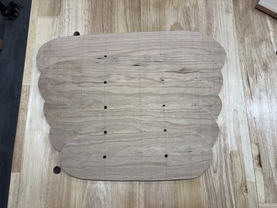
1762719801731.jpeg

The lifts are glued together and shaped using edges of the lifts as guidelines:
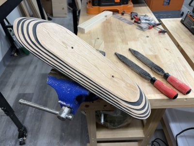
1762719971635.jpeg

After some time the smooth hull shape appears!
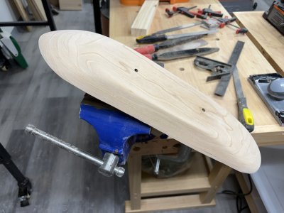
1762720025859.jpeg

Notice that the exterior of this hull is completely convex in nature. This made shaping the hull a relatively straightforward task. Gracie's hull is much more complicated having both concave and convex surfaces.

In the next post I will explain why I have chosen to use vertical / bottock lifts for my model of Gracie S.
 
Before I get going on the model I'd like to say how this thread may be a little different from a standard build log. My aim will be to present material in an organized manner that clarifies not only how I am doing the work, but why I've chosen to do the work in a particular way. However, since most everything in model ship construction can be done via multiple methods, I will try to point out alternate ways when I can. I expect that this thread will be monitored by others from the Teacher's Lounge and that they will chime in as the work proceeds. Moreover, I expect their input will not only enhance what I present, but will also challenge and critique me in a completely honest fashion.

I'm not going to write much in this thread about why / how Gracie S. was chosen as a modeling subject as I feel that those reasons have / will be discussed in other parts of the School. I will reiterate that the ship was chosen with the idea that the hull could be fabricated in a variety of ways - notably POB, POF, and via lifts - and that multiple builds would be presented. I volunteered to give lifts ago - but at that point it had not been decided if I would used waterline or buttock lifts for the model.

Dave Stevens graciously provided me with TIFF files containing the HAMMS plans for Gracie S. I brought the files to the local Digi Copy and had copies made at the scale of 1:48; i.e., 1/4" to a foot. At this scale the two central lifts in the model will be approximately 23" long - several inches longer that the pilot schooner Phantom modeled at the same scale. I studied the plans for quite awhile determining how I would make the model and where difficulties would likely present themselves.

Simultaneously with the development of the Gracie S. project, in the Teacher's Lounge there were discussions as to building materials for archivable models. A couple of wood species were discussed as good choices for a solid hull with white pine and yellow poplar coming to the top. These species are said to be easily worked and also hold good edges. I finally settled on Yellow Poplar (Tulip Poplar) Liriodendron tulipifera. Here, I will pass on advise I was given - when buying Poplar be sure it is not Aspen!

So why vertical / buttock lifts? Three major reasons had me make this choice. First the center line of the hull would naturally be recorded by the joining of the two central lifts. (Note, the centerline can also be preserved by using horizontal lifts that are split down the middle.) Second, and probably the one carrying most weight, I felt that the grain direction would be advantageous when shaping the lower portion of the hull near the sternpost. Third, I've never made a model using buttock lifts and this would give me the opportunity to have that experience.

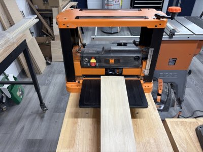
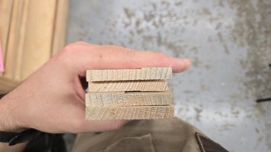
Getting the wood came next. I purchased (more than) enough of this material from a local Menards. This was done after making sure that their poplar was truly the type I needed and not Aspen which is sometimes marketed as Poplar in similar stores. The cost was higher than purchasing the building material at a local lumber yard; however, the wood I purchased was of very good quality and little waste would be made during the milling process. At the lumber yard Yellow Poplar boards contained more knots and would need to be split with a band saw prior to finishing to the desired ½” sheets needed for the lifts. The wood I did purchase could go straight to the thickness planer. I have a Wen 13-inch Spiral Blade Benchtop Thickness Planer that does a fine job thinning material. It can produce flat boards down to 1/8” thick (thinner if you ride your material on another board). I find the thickness planer to be a ‘safer’ alternative to using a jointer if the wood is already square. It turned out that I used 16' of 6" x 1" popular boards from Menards. The actual dimension of their boards is 5 1/2" x 3/4".
 
Here's a look at the body plan for Gracie S.:

1762729583372.jpeg

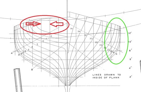
The vertical lines are define the width of the buttock / vertical lifts. The width at 1:48 scale (red arrows) is 1/2", with the exception of the most exterior lift (circled in green) which is slightly wider. Thus for my purposes I needed to prepare a good amount of 1/2" thick material and a little bit of ~ 5/8" material. Here the thickness planer is connected to the shop vac and ready to thin some wood.

It is also very important to observe the printed comment: 'LINES DRAWN TO THE INSIDE OF PLANK'. Should one use the plans as drawn for a solid hull, which I will be doing, the expectation is that the hull will later be planked. If one wished to make a solid-hull model of Gracie S. that was not to be planked, then the plans should be redrawn to account for the planking thickness.
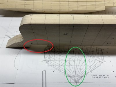
1762729885242.jpeg

I'm lucky to have the space and resources to own some larger machines (many of which I will put to good use in this project), but there are other ways to get the job done. You may have a friend or relative that has the machinery to mill the wood, there may be an 'open shop' nearby where you can get time on the needed tools, or you may find a business to mill your wood (locally or an online order). Perhaps you rely on hand tools and could get out one of those large planes (maybe not!).

Another alternative is to choose the scale of you model to match the wood you can easily obtain. For example, Gracie could be modelled at 1:96 scale where the lifts would be 1/4" - a standard thickness of basswood sheets at the local hobby store. Or if you like these 3/4" thick Poplar boards, you could increase the scale so that the lifts are 3/4" inch - no milling needed, but the hull would approach 3 feet in length!

The shape of each lift is read from the sheer plan. I've placed a few arrows on the plan so that a few notes can be made. The purple arrow marks the top of the cap rail, the red arrow marks the top of the bulwark, and the blue arrow marks the sheer at the (aft) deck. The fore deck is dropped below this line. The green arrow marks the division of the middle lift and keel/stem/stern structure.

I needed to make a decision as to build the solid-hull to the top of the bulwark or to the sheer line. Ultimately I plan on having a planked deck, waterways, and bulwark stations visible on the model. To do so I will need to have the hull structure stop at the sheer line where the waterway will be placed. Hence I can originally build to this line - or I build higher and then remove material. It should also be noted that the hull has tumblehome aft. A plus to building to the top of the bulwark and then removing it is that you can better continuously shape the hull to bulwark juncture - but then some care is need to remove the excess material. Conversely, building the solid-hull to the sheer would require additional attention to the hull shape at he bulwark juncture.

I decided to cut all my lifts to the sheer line as shown in the plans. But I am considering a compromise between the two options - temporarily attaching material to represent the bulwark during the hull shaping process.

1762731053536.jpeg
 
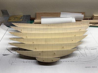
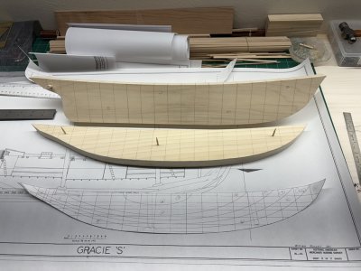
Fabricating the lifts went smoothly. I started the work this past Wednesday and had the lifts completed yesterday (Saturday). Three days of work, as Thursday I needed to have an endoscopy and for some reason its advised that you don't use machinery the rest of the day. Here's the result:

1762733502287.jpeg

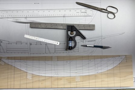
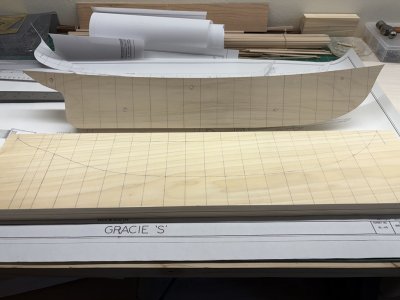
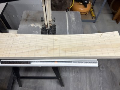
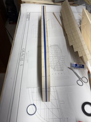
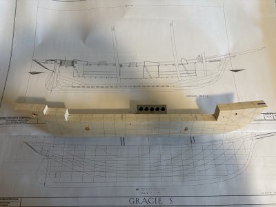
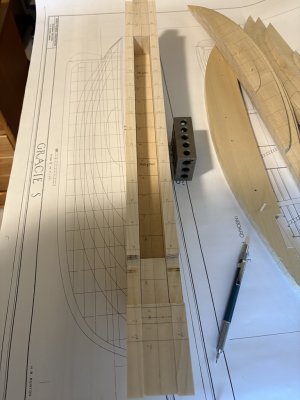
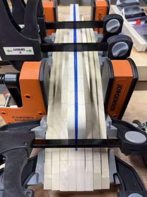
The lifts were made in order from inside to outside. I started by cutting a copy of the sheer plan along the outline of the 'middle' lift - so along the sheer (blue arrow) and around the keel structure (green arrow). the plan was taped to a milled board and the outline of the shape was transferred to the board along with the station lines. This board was doweled to a match board and then the outline of the lift was cut on a band saw. The shape was then finished using a spindle sander. The process was repeated for each lift - remembering that the last (smallest) lift was made from thicker material.

1762733584525.png

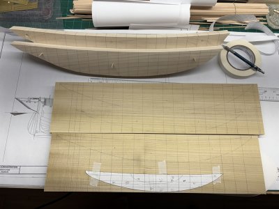
Here's the process illustrated for the second lift. The sheer plan has been cut to the profile of the second lift and taped, using drafting tape, to a piece of wood that has station lines marked. While the sheet of paper is not as stiff as a posterboard template, I still find it as or better to use. First, with a good pair of scissors I can cut the paper closer / smoother to the printed contour. Once it is taped in place, I use one hand to keep the paper tight to the wood during the tracing process. I use drafting tape because it releases easily from the plan that needs to be used a few more times!

1762734041300.jpeg

After the plan was removed the board was clearly marked. Note in this picture the middle lifts have been doweled with 1/4" poplar dowels. When I showed the middle lifts in the Teachers Lounge, bamboo skewers were recommended as an alternate doweling material. I gave it a try in the second lift and liked it - so the remaining lifts all got skewered.

1762734053650.jpeg

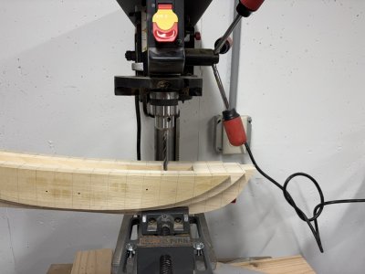
Unfortunately, I didn't take a picture of an intermediate step between these two pictures. The marked board was clamped to a matching board and holes for the skewers were drilled on a drill press. Each lift was cut at the deck sheer first and then brought to the thickness sander. I wanted to have the best chance I could have for the top curve of each lift to match when they were assembled. Sanding the top curve with excess material on the ends also minimizes the chances of sanding a dip at the ends of the lifts.

1762734072529.jpeg

In this picture the sheer has been sanded and the piece has gone back to the bandsaw for the lower edge to have been removed. Now some more sanding is to be done. I used 150 grit sanding sleeves for this work. I took this picture with the lift sitting on the 'back-side' of the table was a reminder to me as to how important it is to keep the work piece flat on the table if a right angle is desired. Also, there is a lot more room on the back of the table to steady the work piece than on the front-side.

1762734086816.jpeg

With the sanding done on lift two it was time to move on; cut another piece off the sheer plan, ....

1762734127003.jpeg

Two sets of the smaller lifts fit easily on the 5 1/2" wide Yellow Popular - here lifts 3,4,5, and 6 are laid out. Number 7 got its own smaller but thicker piece of wood.

1762734140570.jpeg

That's how I did the work. Obviously, the drill press is not absolutely needed - a hand held drill would do the same. Having the bandsaw - even the light duty 10" Wen bandsaw I have - is a luxury, the same work (albeit slower) can be achieved with a coping saw. Likewise rasps, files, and sandpaper could be used in place of the spindle sander. Here again, choosing the scale / size of a model can be influenced by the tools you have at hand. Making a solid-hull Gracie S. at the 1:96 scale would not be overwhelming with a collection of hand tools.
 
Back
Top