The Naval Cutter ALERT- 1777, POF by Jimsky

HI Jim, the double bolting will not be visible after installing the doubles as most of the doubles have the third half rib installed next to them covering it and there is only 4mm gaps for the others so so unless your going for completeness or have a magnifying glass to view, only you will know!

Also the 3 internal Footwales cover most the the internal chuck pins. You only find this out when you install them!
Many thanks for your observations, Paul. You are correct, the bolting (if you choose to accept them) will not be visible for the most part. First of all, inside the hull, they will be hidden behind multiple internal structures (crew accommodation cabins), also bear in mind the deck structure and partial planking... I just realized, that even cabins will be hidden for the most part. But... the bolting will be visible outside the hull, also it should strengthen the frames, as in my case they go thru the chocks.
I guess both, you and Uwe convinced me to opt-out bolting the double-frame. Thank you both for saving me some time. Thumbs-Up
 
It is time for the progress update, and I'd like to thanks everyone for your valuable comments and likes, those are the indication that we moving in the right direction. :cool:

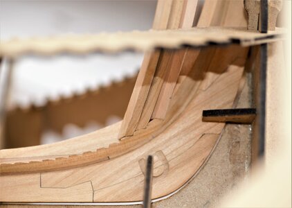
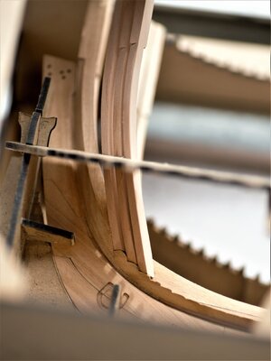
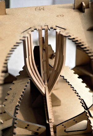
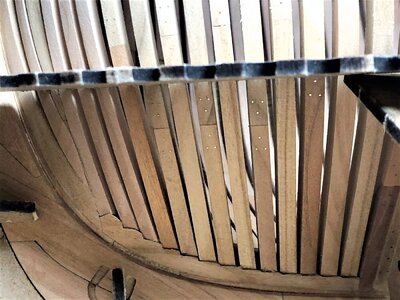
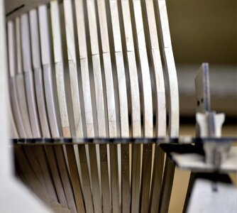
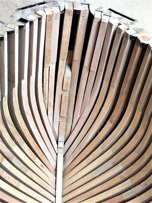
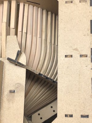
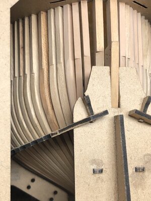
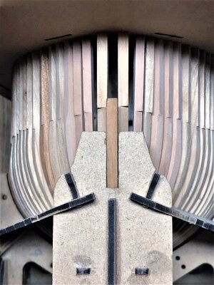
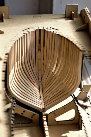
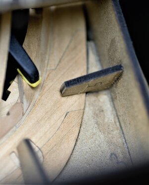
Today we are finishing with 'cant' frames. All of the 'how to' and 'gotchas' we have discussed in previous posts. To finish I will provide mostly the photos. However, installing the cant frames require some virtual imagination and measure 3 times before the final shape. You should definitely follow the instruction manual. First 4 frames (1, 4, 2, and 3). This is the correct order. Failing this order will create additional headaches.
I didn't modify the rising wood slots (as @Maarten did in his build) and this resulted in some trouble positioning. Each frame must be 'adapted' to its slot in the rising wood e.g. it must sit perfectly flat (no horisontal\verical gaps in the rising wood slot and keelson).
The really great help is the notches in the berth, they are the direction guides. Starting from the top-notch of the berth, slide towards the middle notch and then corresponding rising wood notch until the frame touches the keel. Check each side of the frame for gaps, if you see them - sand out excess and try fitting again. Repeat 'adopting' the frame until no visible gaps are seen, or your personal acceptance level. This is a relatively slow process and requires as much patience and attention for a successful job.
Frames #1 and #4 are most important for correct placement, their proper positioning will help with frames #2 and #3, but frame #3 is most challenging, IMHO. Use of templates a MUST!

First frames are installed
600_0910.jpg
600_0940.jpg

600_0939_1.jpg
600_0937.jpg
600_0938_1.jpg

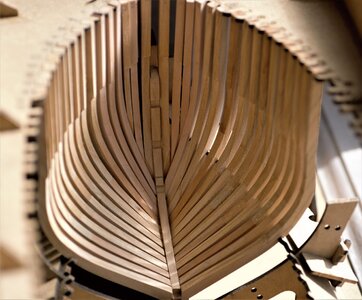
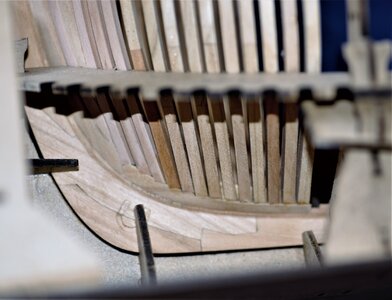
Complete set of cant frames in-place.
600_1058.jpg
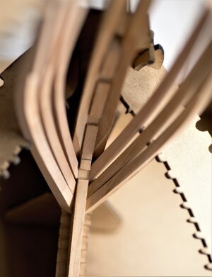
macro view
IMG_1693.JPEG
600_1005.jpg

IMG_1697.JPEG
IMG_1696.JPEGIMG_1695.JPEG
IMG_1694.JPEG
600_1027.jpg
600_1026.jpg

Stern 'cant' frames assembled\instaled the same way, but...we will install them after completing assembly the Stern.
See you soon and the agenda will be Stern section. ;) Will be working on Transom.
 
Last edited:
When you say "The really great help is the notches in the berth, they are the direction guides." what do you mean?
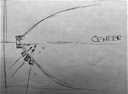
Thank you, John. Really appreciated your comments and question. If you take a look at the notches, they made at various angles against the virtual centerline. Take a look at my sketch below. The notch arrow at the different angles against the centerline. While the frames are beveled they still perfectly square into the notches. If you slide the frame into the notches it will go with the correct angle against the centerline. Hope this cleared in a bit. English, is not my native language, though.

IMG_1704.jpeg
 
You really love your new Macro, don't you? Me too!!
Thank you for these great and helpful pictures!
Yes, Markus! I do love the macros. The idea is to help see blemishes\inperfections, the normal vision wouldn't pick up. I am working wearing magnifying glasses 1.25 :) I am glad you like it, thank you!!
 
Hi John, the upper berth top and the lower berth removable guides, hold the frame in the correct position whilst it dries As long as the rib sits in the berth hard against the lower and upper guides its correctly positioned.
The idea of the lower guides is sensational.
Thanks, John! Obviously, you explained it much better than I would. ;) Many thanks, it is very much appreciated.
 
Very good work my friend - and we can see, that you have a lot of fun with this kit, or? Thumbsup
Oh...yes, Uwe! :)You are correct, my friend, it is a blast! I can not even have enough words to explain how much I enjoy working on this kit. It does have all of the elements for the introductory of the POF kit. The simplicity of the frames assembly (thanks to the templates idea) makes this kit a real joy to work with. In the same token, it is imperative to not underestimate the difficulty level of the entire ship construction as the whole.
I am sure, you have as much fun building Le Coureur! I am really glad to see, both kits are in the group builds on SOS and people have fun, IMHO.
I think we can say for both @CAFmodel and @Trident Model - Mission accomplished! Both are great kits to work with. Good job Tom and Trident. Thumbs-Up
 
Greetings everybody!
It is not a progress update, it is rather something I'd like to share with my discovery. A few posts back we have discussed the 'bolting' and how to imitate them. So... we kinda agreed to use 0.4mm wire on chocks and plain scarfs (brass or soft steel). I am happily using brass wire, over time it will oxidize itself and give that 'greenish' dark spot.
What is challenging is to make a decision imitating the head of this bolt, IMHO. Maarten @Maarten used the method of Dr.Mike rolling the wire in the flat surface with the knife until it creates a 'mushroom' type head. This is a relatively fast process (roll and cut), but require each head sanded to make it nice. I like to use the concave bur, it does create a very nice and smooth mushroom head, but...it is a slow process. Also, this bur can be used to shape rolling bolts.

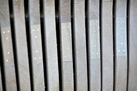
Nither of the above methods, I can use it in my build, though. I 'bolt' frames before final sanding, that means, once I will sand the hull, all of the nice mushrooms will go for good. I was accepted this from the beginning, but...something interested discovered and really want to share with you. Below, is the macro of the frameset after preliminary sanding 180 grit sandpaper.

As you can see, the head is absolutely flat
600_1090 (2).jpg

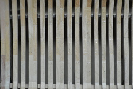
And here is the magic
600_1089.JPG
The heads are nicely rounded as the mushroom. What happened? What is the magic behind this? Does anyone guess???
 
the wood sanded away faster leaving the pin slightly raised. How much sandpaper did you kill?
Close... but no cigar! As you can see in the first photo, the 'bolts' are flush with the timber. I use my sanding blocks, I made. We call them in Russia 'suharick'. But honestly, not much sanding required, If frames assembled in the templates. I will elaborate later on sanding. Thank you for trying!!!
 
The Magic?- Let me guess:
  • You dampened the frames with water before sanding and after they dried fully the wood shrank leaving an exposed bolt head?
  • You used those bur tools from the outside and they pushed the bolts through on the inside?
  • They are still flat, just the camera angle/lighting that makes them look rounded.
  • Leprechauns worked during the night to give you an early Christmas gift?
 
Maarten @Maarten used the method of Dr.Mike rolling the wire in the flat surface with the knife until it creates a 'mushroom' type head. This is a relatively fast process (roll and cut), but require each head sanded to make it nice.
I remember seeing how this was done (maybe it was in one of Kudin's videos)
Do you have a link on this process?
 
The Magic?- Let me guess:
  • You dampened the frames with water before sanding and after they dried fully the wood shrank leaving an exposed bolt head?
Oh...no... Way complicated, I would never do that!!
  • You used those bur tools from the outside and they pushed the bolts through on the inside?
Good guess, and a very good suggestion but...
  • They are still flat, just the camera angle/lighting that makes them look rounded.
They are rounded and it is not the camera\lighting effect! Magnify the image, you will see rounded heads
  • Leprechauns worked during the night to give you an early Christmas gift?
No earlier gifts for Jim, only earlier vote (LOL)
 
you pushed the bolts a little below the surface and after sanding you pushed it back from the outside?
Or you drilled before sanding and inserted the bolts after sanding?
 
Back
Top