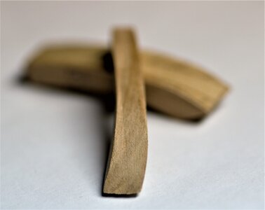
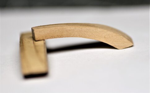
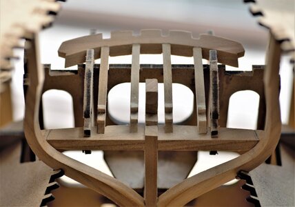
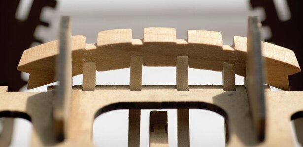
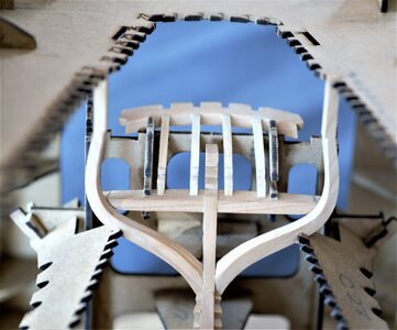
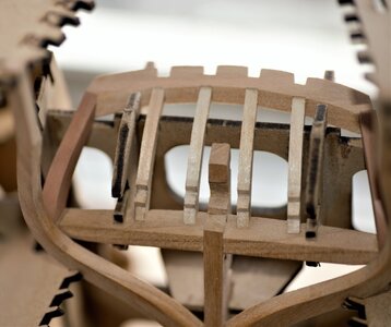
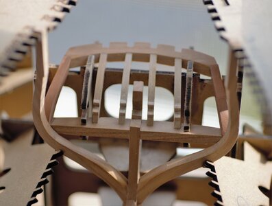
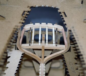
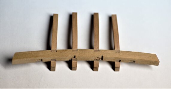
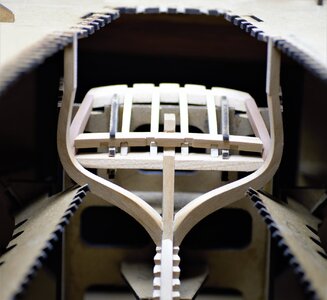
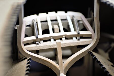
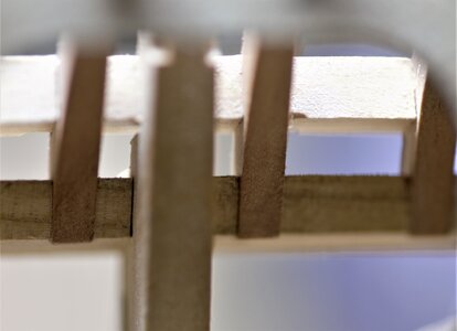
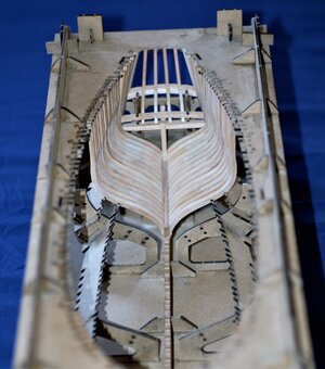
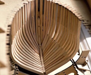
The Naval Cutter ALERT- 1777, POF by Jimsky

you pushed the bolts a little below the surface and after sanding you pushed it back from the outside?
Or you drilled before sanding and inserted the bolts after sanding?
Thanks for the try, Poul! No, neither of those. It is much simpler than this. I thought to insert bolts after the final sanding but opted out because all the bolts I have inserted was fixed with a drop of very thin (like water) CA glue.
 
Whatever you did, it looks great!
Mmm, might have to do another Alert with brass....
Thanks, Roger! The 0.4mm bras are almost invisible to bear eyes, at least to mine ;) Black dots would be too much. for my taste. But... anyway, most of them will be hidden inside.
 
The heads are nicely rounded as the mushroom. What happened? What is the magic behind this? Does anyone guess???
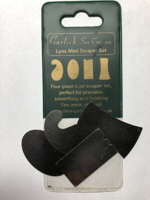
Alright, folks..., it is time to reveal the magic. Many thanks to all who tried guessing. Well, the answer is... Wood Scraper!!! Yes, that simple!! I have a set of miniature scrapes mostly used in the violins makes. They are made from high-end steel and came burnished (ready to use).
When I scrape the frame, I touched the brass pins (bolts), the effect was a kinda 'bump'. This explains as the wood timber is softer than brass, but brass is softer than steel. By scraping (removing) some tiny timber material the brass pin exposed with a rounded head...

Here is the scraper set I use for about 5 years.
IMG_1707.jpeg
 
Suppose you can't even see this with the naked eye.
You are correct, John. You cannot see with bare eyes, at least, I cannot see. What makes it even more pitty, it will be hidden under various cabin structures and deck beams, partially deck planks. ;) But... it is something, I called an acceptance level and self-satisfaction.
 
Assembling the Stern

Many, many thanks to all of your interest, comments a 'Likes'! We are moving to the next chapter of our build and we will talk about the Stern section.

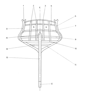
Before we move to the actual build, let's take a look and learn some of the new terms we will use for this assembly. NOTE: The draft images are taken from the AOTS book by Peter Goodwin. They are only for educational purposes.

Disposition of the Stern timbers

1604852084444.png

Take a look at the above image. Primarily, our interest with:
  • #10 Wind transom. In our kit, this is part BL30, and we have already installed it while assembling the keel structure.
  • #9 Deck transom. In our kit, this is part BL31
  • #7 Helm port transom, part # BL32
  • #5 Side counter timber, parts AL772 - AL77
  • #2 Counter timbers, parts BL41, BL39 and BL37
  • #11 Fashion piece. in the kit parts AL71
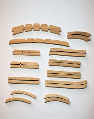
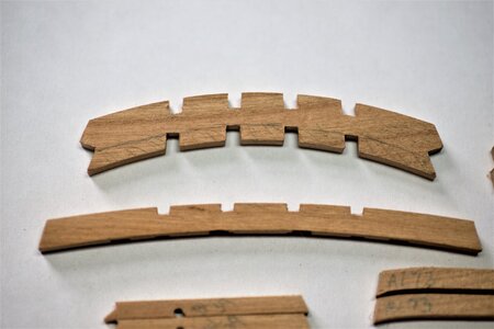
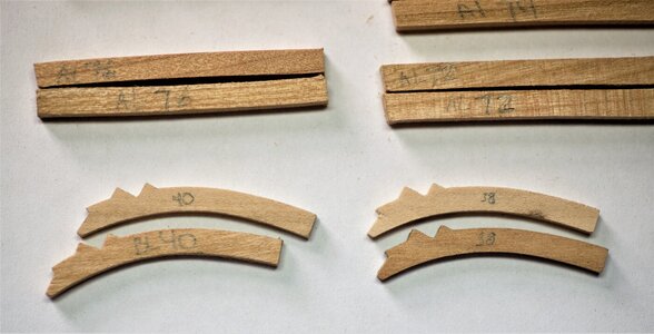
For the most part, these are the parts the Stern made off and the corresponding parts labeled in our kit. Below are the parts from the kit.

600_0977.jpg
600_0978.jpg 600_0979.jpg

As per the instruction manual, we will start by assembling Fashion pieces AL71 (cant frames). These are assembled\beveled the same ways as the Stem (bow) cant frames. Each of the Stern cant frames has the assembling template and fairing(beveling) templates for the inside\otside edge. When gluing AL71 to the keel make sure you have positioned the frame as shown in the manual on page 16. Image 5.15, 5.16, and 5.17 shown in different projections. Both sides of the frame must touch the 'wind transom'. I just realized that I didn't take a photo with the frame installed. :(

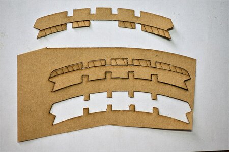
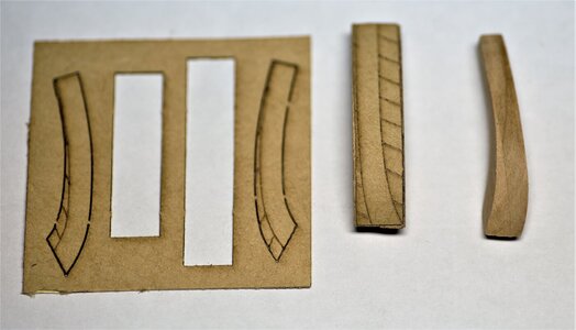
Helm port transom requires beveling on both sides. Trident provided paper adhesive templates. Once the template affixed, carefully bevel the shaded area

600_0981.jpg

Here is both sides are shaped
600_0986.jpg

600_0987.jpg

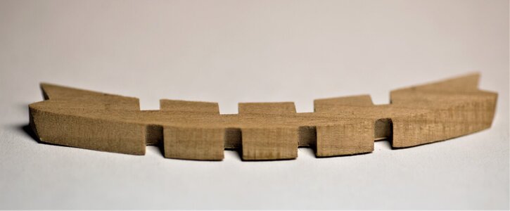
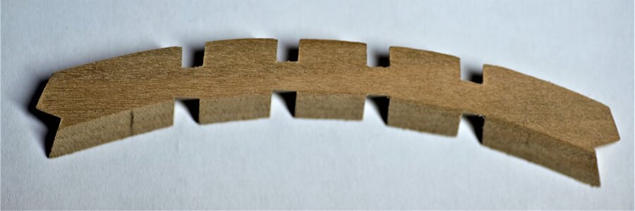
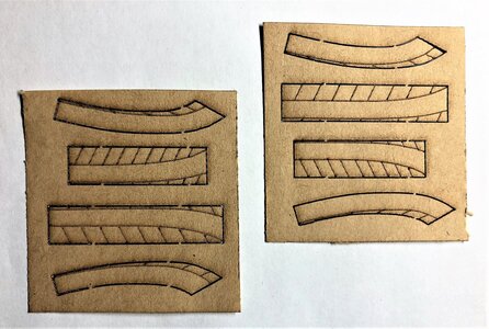
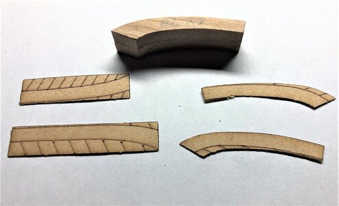
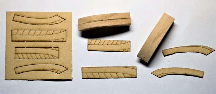
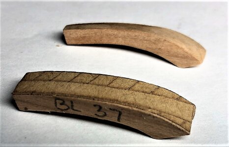
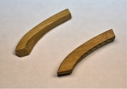
The helm port installed in the berth, and it connects with the corner counter timbers parts BL37. Those timbers have a very interesting shape and made out of two pieces BL37 glued together (side by side), many thanks to the tip @Jolley Roger. While the shape looks complex, thanks to the beveling stickers it makes the job a lot easier.

IMG_1722.JPEG
IMG_1724.JPEG

Stickers are for both: left and right side counter timbers. Each timber requires 4 stickers to shape. But, please. don't put all stickers at the same time. Affix the top and bottom stickers first, shape the part, and then affix the side templates to finish the process. Below multiple photos depict the various progress stages.

600_1214 (2).jpg

On the right, the part is already shaped. On the left, both top and bottom stickers applied and part ready for shaping. DO NOT put all 4 stickers on all 4 sides.

600_1215.jpg
IMG_1726.JPEG 600_1217.jpg
600_1220.jpg 600_1219.jpg

To be continued...
 
Continue with the Stern assembly. Having fun yet? The next step is to connect side counter timbers with the Helm port transom. You must pay attention to counter timbers (part BL38 and 40) those parts have the notches in both Wind and the Helm pot transoms.
  • measure the parts BL38\40 and widen the notches in both BL30 and BL32 so they fit snug.
  • They must be installed without the gaps.
This is why before gluing parts BL37, I suggest dry-fit parts BL38 and BL40 with a connection of part BL32 (Helm port transom) and side counter timbers (BL37). From my experience, parts BL37 need shaping at the ends to fit nicely into the ends of the part BL32.

600_1012.jpg

View from the back. Note, there are no gaps.

600_1014.jpg

Here is the photo of the fashion piece (frame AL71) 600_1016.jpg

Once you satisfy with all parts fit, only then you can glue the side counter timbers in their respective places (both left and right sides) 600_1018.jpg
600_1019.jpg
600_1020.jpg

Some macro from the back of the Helm port transom, all parts are fit snug without the gaps.
600_1021_ed.jpg

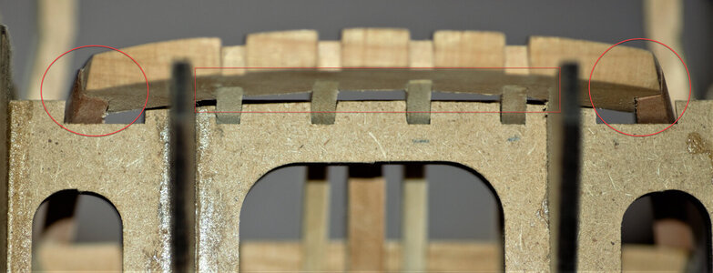
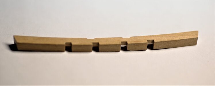
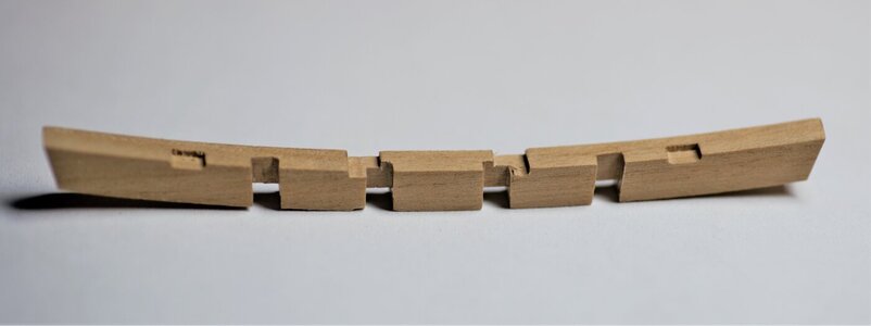
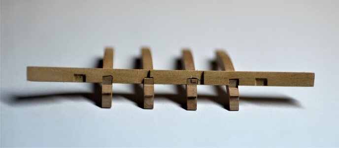
Now, we will talk about the Deck transom, part BL31. Well. this is another part of the Stern and it is installed using the berth parts CL15 as the guides. Deck transom has notches, the size of those notches has to match the width of counter timbers BL38\40. Also, you may need to cut a bit (both ends) so it fits better, and widen the berth parts. To better understand, and visualize how this part attaches to the rest I made some shots in various views.

The Deck transom with notches widened and cleaned. Back view
600_0994.jpg
Side\front view
600_0995.jpg
Bottom view
600_0996.jpg

Counter timbers dry-fitted the way they will be glued.
600_0989.jpg
600_0991.jpg
600_0992.jpg
600_0993.jpg

...and now, the Deck transom installed in place. and all parts glued.
600_1024.jpg
600_1023.jpg
And macro from the back
600_1000.jpg

To be continued... stay tuned
 
Time for the build update, and the first thing I'd love to thanks all of you my friends, who showed interest with your 'likes' and comments. Needless to say, they are really good motivations to continue.

So I will continue...Today, we will finish with side counter timbers and the Stern cant frames. I decided to combine both counter timbers and Stern cant frames in one post.
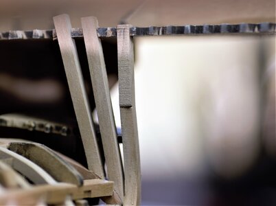
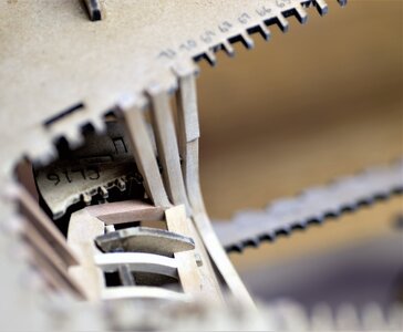
All counter timbers parts AL72-AL77 have their own distinct shapes. The most challenging counter timber to install is part AL72. It requires 'shape & tries' methodology in order to shape correctly. remove a small amount and test\try until happy with the result.

600_1029.jpg

600_1030.jpg

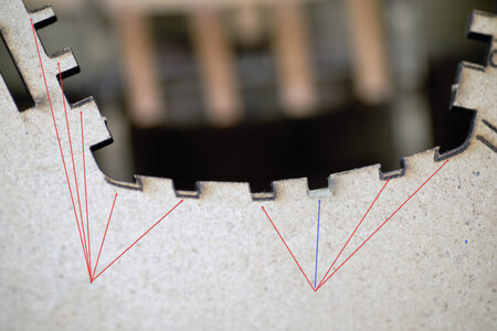
Pay attention to the laser marks notches on the berth. They have to be beveled (where appropriate). The bevel allowed to position counter-frames with the proper angel. Check the image below. The blue arrow pointed to an already beveled\shaped notch.

600_1008_edited.jpg

The rest of the timbers also need to be proprietarily shaped (before gluing) to their positions
600_1025.jpg

The length of the counter timbers has sufficient material in case you didn't shape for the first time. If you initially shape the frame correctly the end of the frames might stick over the berth, it is normal.

IMG_1720.JPEG


IMG_1718.JPEG

IMG_1719.JPEG
600_1028.jpg

With this, we finish with the counter timbers and moving to Stern cant frames. More fun ahead so stay tuned.
 
Stern cant frames.

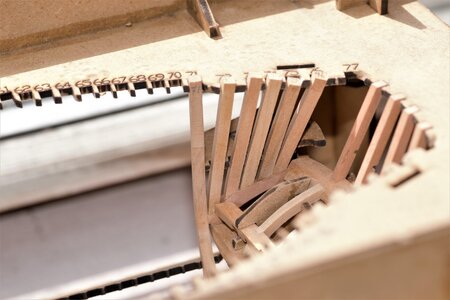
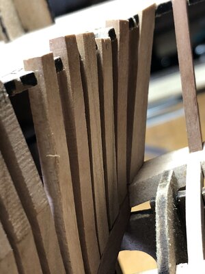
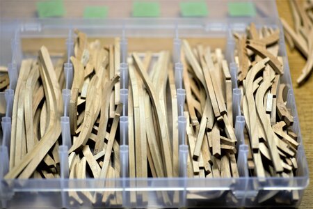
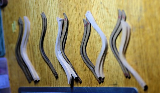
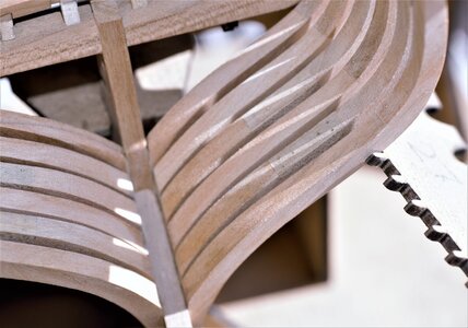
The first Stern frame Part AL71 has been already installed as part of the transom assembly. The rest of the frames must be processed the same way as the Bow cant frames. The frames must be assembled and glued using the MDF jigs. Pay attention to the correct numbers. There are some mismatches specifically for frames 71 and 72. I like Zolly's @zoly99sask idea to separate frame parts in bags for further processing. I have used plastic boxes to store frame parts and lately assembled frames.

600_0887.jpg

600_0888.jpg

Assembled frames, need to bevel using the MDF templates. No need to discuss the procedure, as it is the same as for the bow cant frames.

600_1037.jpg

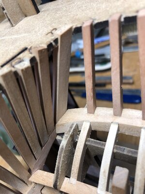
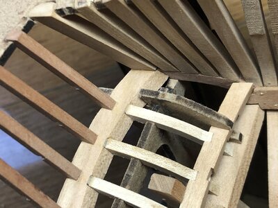
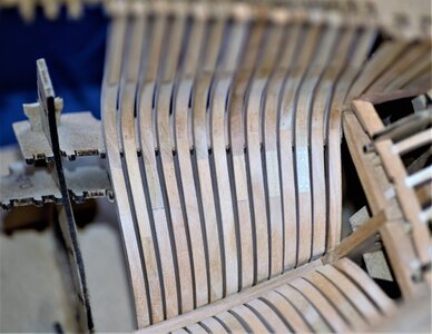
It is advisable to dry fit all the frames prior to permanently gluing, check their positioning against the keel and rising wood. There shouldn't be any visible gaps, from different views, when frame fitted. The top berth notch should hold the frame while you 'adopt' the frame into its position. Only when you 100% satisfied proceed to glue. Fit\glue frame by frame: port and starboard sides, then move to the next frame.

First frames are installed
600_1049.jpg

600_1050.jpg
600_1051.jpg

And here all the frames in place dry fitted.
600_1043.jpg
...and glued to the frame.
600_1053.jpg
Elevated view from the risers (starboard side)
600_1057.jpg
View from the risers (port side)
600_1063.jpg
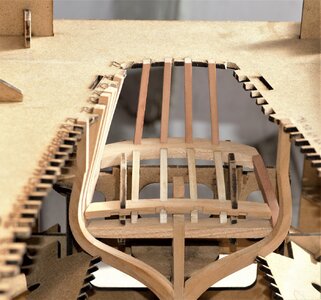
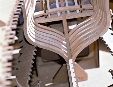
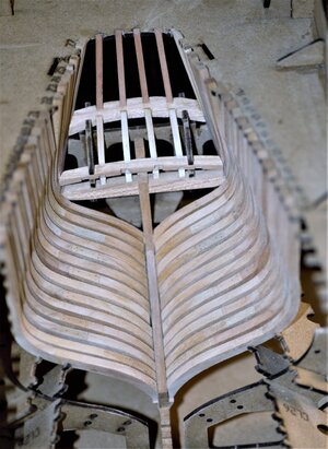
the entire view of the Stern and bow sections completed.
600_1054.jpg

600_1026.jpg

Well...we are done with all cant frames and counter timbers. Be alert for even more fun as we turn the next chapter while assembling 'full frames' e.g. midsection. to be continued...
 
Continue with the Stern assembly. Having fun yet? The next step is to connect side counter timbers with the Helm port transom. You must pay attention to counter timbers (part BL38 and 40) those parts have the notches in both Wind and the Helm pot transoms.
  • measure the parts BL38\40 and widen the notches in both BL30 and BL32 so they fit snug.
  • They must be installed without the gaps.
This is why before gluing parts BL37, I suggest dry-fit parts BL38 and BL40 with a connection of part BL32 (Helm port transom) and side counter timbers (BL37). From my experience, parts BL37 need shaping at the ends to fit nicely into the ends of the part BL32.

View attachment 191759

View from the back. Note, there are no gaps.

View attachment 191761

Here is the photo of the fashion piece (frame AL71) View attachment 191762

Once you satisfy with all parts fit, only then you can glue the side counter timbers in their respective places (both left and right sides) View attachment 191763
View attachment 191764
View attachment 191768

Some macro from the back of the Helm port transom, all parts are fit snug without the gaps.
View attachment 191769

Now, we will talk about the Deck transom, part BL31. Well. this is another part of the Stern and it is installed using the berth parts CL15 as the guides. Deck transom has notches, the size of those notches has to match the width of counter timbers BL38\40. Also, you may need to cut a bit (both ends) so it fits better, and widen the berth parts. To better understand, and visualize how this part attaches to the rest I made some shots in various views.

The Deck transom with notches widened and cleaned. Back view
View attachment 191773
Side\front view
View attachment 191774
Bottom view
View attachment 191775

Counter timbers dry-fitted the way they will be glued.
View attachment 191776
View attachment 191778
View attachment 191779
View attachment 191780

...and now, the Deck transom installed in place. and all parts glued.
View attachment 191785
View attachment 191786
And macro from the back
View attachment 191787

To be continued... stay tuned
Difficult framing, man. You did excellent job! What a kit!
 
@Gennaro and @PoulD Thank you, gentlemen!
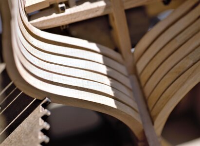
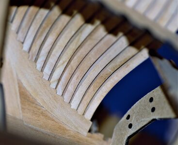
You would be surprised, but the framing is not that difficult as it sounds\seems to be. Yes, they are challenging and required some attention but Trident Models made it easy for us. The frame assembly\gluing boards alone with MDF templates for beveling\fairing are a real jewel for us. I found, if a frame properly made installing is just a matter of 'adoption' & fitting and it creates a nice even flow with adjacent frames without actual sanding. I am really impressed and happy!
 
Now you are going at warp speed Jim, looking great.
To avoid getting bored by repetative work I a m doing my build frame by frame.
So you will overtake my build in the coming days :)
Thank you, my friend, it is just the appearance that I am building fast... However, I am addicted (in a good way) to this kit\build and use every possible chance, and use in full when having one.
 
Back
Top