
-

SUBSCRIBE TO SHIPS IN SCALE TODAY!
The beloved Ships in Scale Magazine is back and charting a new course for 2026!
Discover new skills, new techniques, and new inspirations in every issue.
NOTE THAT OUR NEXT ISSUE WILL BE July/August 2026 -

Win a Free Custom Engraved Brass Coin!!!
As a way to introduce our brass coins to the community, we will raffle off a free coin during the month of August. Follow link ABOVE for instructions for entering.


You are using an out of date browser. It may not display this or other websites correctly.
You should upgrade or use an alternative browser.
You should upgrade or use an alternative browser.
USS Constitution by BlueJacket 1:96
- Thread starter g8rfan99
- Start date
- Watchers 22
-
- Tags
- bluejacket constitution


excellent corrective surgery there, Frank. Yes, I have no doubt you'll be happy with your decision.
congrats
congrats
So time for an update. After repairing the bulwarks, I of course had to paint everything. As I was doing this, I realized that the entire inside really needed a fresh coat. It is surprising how much was chipped/rubbed off while working on the gun deck. In any event, I repainted the entire inside of the bulwarks. With a little wood filler and paint, it is difficult to see where the seam is on the repair
![20260627_110714[1].jpg](https://shipsofscale.com/sosforums/data/attachments/598/598949-6e27749b7e7dadaf3d62f3debdf8f0e3.jpg?hash=oR7_IPBIen "20260627_110714[1].jpg")
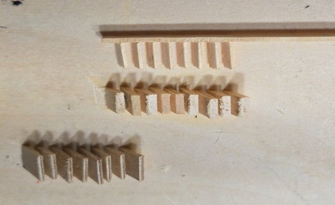
Before getting started on the eyebolts etc. for the spar deck guns, I remembered that I still needed to get the stairs in place leading down to the gun deck. My original plan was to use either the plastic ones from the Revell kit or the cast metal ones from BlueJacket. The problem with either of these is painting them to look like wood. I know there are a lot of folks out there who do a fabulous job of this, but it is not a skill that I have mastered yet. Despite my best effort, they still look "plastic". I decided to give a try at actually making them from wood. I used the ones from the Revell kit to get some measurements for the angles and the thickness of the various components. My plan was to make some spacers for the steps, cut these at the proper angle and glue them to a flat surface. Then I could just slide the steps into the slots and glue the sides on.
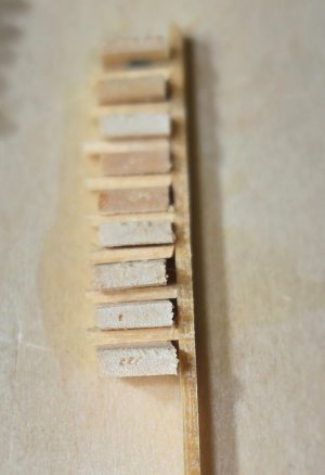
On the first attempt, I actually glued both sides of the ladder onto the steps and then had to wiggle the ladder out of the spacers at an angle. That was not easy trying to get the ladder to move up and sideways without ripping of the spacers. On the subsequent assemblies, I just glued one side and once dried just slid it out sideways before glueing the other side on. This worked much better
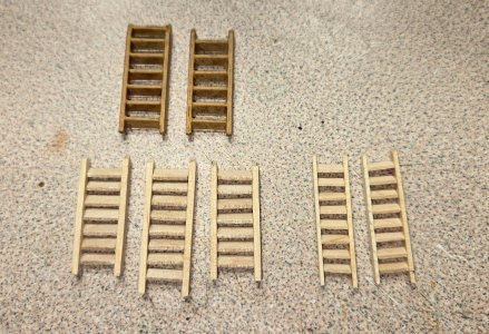
The ladders on the main hatch and the aft hatch are wider than the companionways, thus the difference in size. The second photo shows the plastic painted ladders just for comparison. And here they are after a little stain
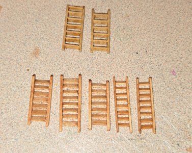
I still have two more companionway ladders to do and then I will install them
Before getting started on the eyebolts etc. for the spar deck guns, I remembered that I still needed to get the stairs in place leading down to the gun deck. My original plan was to use either the plastic ones from the Revell kit or the cast metal ones from BlueJacket. The problem with either of these is painting them to look like wood. I know there are a lot of folks out there who do a fabulous job of this, but it is not a skill that I have mastered yet. Despite my best effort, they still look "plastic". I decided to give a try at actually making them from wood. I used the ones from the Revell kit to get some measurements for the angles and the thickness of the various components. My plan was to make some spacers for the steps, cut these at the proper angle and glue them to a flat surface. Then I could just slide the steps into the slots and glue the sides on.
On the first attempt, I actually glued both sides of the ladder onto the steps and then had to wiggle the ladder out of the spacers at an angle. That was not easy trying to get the ladder to move up and sideways without ripping of the spacers. On the subsequent assemblies, I just glued one side and once dried just slid it out sideways before glueing the other side on. This worked much better
The ladders on the main hatch and the aft hatch are wider than the companionways, thus the difference in size. The second photo shows the plastic painted ladders just for comparison. And here they are after a little stain
I still have two more companionway ladders to do and then I will install them
Beautiful ladders and a seamless repair on the bulwarks. Very nicely done.


Hey Frank, it looks like the "steps" you took to make nice looking ladders paid off. Nice work!
I got the last two ladders completed and was going to get these all installed on the ship, but decided to wait, more on that later.
With all that tended to, I was ready to move on to the bulwark details, with the pinrails being first. I was going to use the same persimmon wood I had used for the hatches on the gun deck, but with ta little tie, it seems to have acquired a little color as it has aged. It is now very much the color of walnut, which looks really good, but to me is too dark for the pin rails which have a very bright finish, more like a honey color. I decided to try another wood that I harvested from my property which is Crepe Myrtle. Myrtle wood is a very hard wood, and was actually used to make golf clubs back in the day. It has a very fine grain, so it looks good at scale and holds an edge very nicely.
Having checked and double checked that I now have the gun port locations correct (according to the BJ plans) I made up the pin rails according to the Navy plan 27076 that I got from the museum website. It gives the dimensions of each rail and it's location on the bulwarks. I used the laser on low power to mark the location of the holes on a piece of wood and then used the drill press to actually drill the holes. In order to securely attach these to the bulwarks, I wanted to use pins, so I flipped the rails on their side and drilled holes to accept the pins that would be inserted into the bulwarks. The rails are only .050" thick. I used 24 ga. wire for the pins, which is .020" thick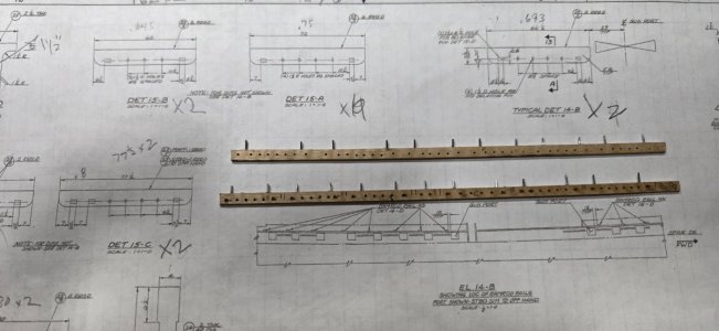
The laser marks will be on the underside and so not visible, whereas the topside has nice clean holes.
After getting all this done, I checked once more to make sure everything fit nicely and of course ran into a problem. It seems that the Navy plans and the BJ plans do not match up. Not totally surprising, since the Navy plans are from 1973. The BJ instructions regarding the size and location of the pin rails is extremely vague, however, they give a very nice belaying diagram for the rigging. So, I used the belaying diagram to determine the length of the rails and the number of holes for each. Thankfully, although being used in different places, all the pieces I had already made up would be sufficient. (big sigh).
So now I just need to get them attached.... big question for all those out there much more experienced than I. Do any of you have a clever way of making sure the holes I put in the bulwarks line up exactly with the pins on the rails?
Also, the Navy plans mention "Ramrod rails" placed next to each gun port, but they are located on the bulwark above the gunports that was added after the 1812 era ( and is not there any more). What were these for and what would have been in their place for this era?
With all that tended to, I was ready to move on to the bulwark details, with the pinrails being first. I was going to use the same persimmon wood I had used for the hatches on the gun deck, but with ta little tie, it seems to have acquired a little color as it has aged. It is now very much the color of walnut, which looks really good, but to me is too dark for the pin rails which have a very bright finish, more like a honey color. I decided to try another wood that I harvested from my property which is Crepe Myrtle. Myrtle wood is a very hard wood, and was actually used to make golf clubs back in the day. It has a very fine grain, so it looks good at scale and holds an edge very nicely.
Having checked and double checked that I now have the gun port locations correct (according to the BJ plans) I made up the pin rails according to the Navy plan 27076 that I got from the museum website. It gives the dimensions of each rail and it's location on the bulwarks. I used the laser on low power to mark the location of the holes on a piece of wood and then used the drill press to actually drill the holes. In order to securely attach these to the bulwarks, I wanted to use pins, so I flipped the rails on their side and drilled holes to accept the pins that would be inserted into the bulwarks. The rails are only .050" thick. I used 24 ga. wire for the pins, which is .020" thick
The laser marks will be on the underside and so not visible, whereas the topside has nice clean holes.
After getting all this done, I checked once more to make sure everything fit nicely and of course ran into a problem. It seems that the Navy plans and the BJ plans do not match up. Not totally surprising, since the Navy plans are from 1973. The BJ instructions regarding the size and location of the pin rails is extremely vague, however, they give a very nice belaying diagram for the rigging. So, I used the belaying diagram to determine the length of the rails and the number of holes for each. Thankfully, although being used in different places, all the pieces I had already made up would be sufficient. (big sigh).
So now I just need to get them attached.... big question for all those out there much more experienced than I. Do any of you have a clever way of making sure the holes I put in the bulwarks line up exactly with the pins on the rails?
Also, the Navy plans mention "Ramrod rails" placed next to each gun port, but they are located on the bulwark above the gunports that was added after the 1812 era ( and is not there any more). What were these for and what would have been in their place for this era?
If memory serves, I made little spacers - on top of which I rested the pin rails. Lining the latter up forward and aft, on the spacers, you should just lightly press the pin rail against the bulwark. That should leave mark's that you can use a pin vise to drill. (I will have to check my own build log to see if I used any fasteners to secure the pin rails to the bulwarks. Or if I just glued them.)
I just checked. On page 17 of 132 in Year 3's build log, I made a note:
"Blast! I should have taken a better picture of the little jig I made to correctly position the pin rails." I honestly can't remember if I used locating pins/nails. But the concept should still work. Make a block the right height for the pin rails. Bevel the bottom of the bulwark side of the block to clear the waterway. Have handy a piece of flat stock about the same thickness and length as your pin rail. Place this and your pin rail on top of the block with the nails/pins facing the bulwark. Line everything up, then tap that piece of stock with a tiny hammer or mallet. That should cause your nails to make marks on the bulwarks. Then get busy with a pin vise to drill into the bulwarks Reposition the block, pin rail and flat stock so that the nails line up with the holes you just drilled then press the pin rails home. (Don't forget the glue). My photo shows the pin rail against the bulwark, the flat stock next to it on top of the block. I don't know why the second block with the dimensions on it is in the photo.
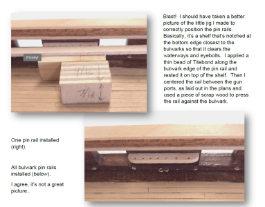
Hope that helps.
"Blast! I should have taken a better picture of the little jig I made to correctly position the pin rails." I honestly can't remember if I used locating pins/nails. But the concept should still work. Make a block the right height for the pin rails. Bevel the bottom of the bulwark side of the block to clear the waterway. Have handy a piece of flat stock about the same thickness and length as your pin rail. Place this and your pin rail on top of the block with the nails/pins facing the bulwark. Line everything up, then tap that piece of stock with a tiny hammer or mallet. That should cause your nails to make marks on the bulwarks. Then get busy with a pin vise to drill into the bulwarks Reposition the block, pin rail and flat stock so that the nails line up with the holes you just drilled then press the pin rails home. (Don't forget the glue). My photo shows the pin rail against the bulwark, the flat stock next to it on top of the block. I don't know why the second block with the dimensions on it is in the photo.
Hope that helps.
Yep, I like to use the sharp nail indentation process in securing items to the bulwarks or deck areas. Continued great work, Frank!
I do too, now...
I wish I thought to do that when I made my Fife rails. Trying to push pins into the bottoms of the stanchions is going to be quite difficult at this point.
Worse, I followed Bob Hunts repeated urging and applied three coats of polyurethane to the deck. Trying to sand little squares to better hold glue is going to be problematic.
I see a long afternoon at the shipyard ahead of me
Cheers,
And Happy 250th 4th...
I wish I thought to do that when I made my Fife rails. Trying to push pins into the bottoms of the stanchions is going to be quite difficult at this point.
Worse, I followed Bob Hunts repeated urging and applied three coats of polyurethane to the deck. Trying to sand little squares to better hold glue is going to be problematic.
I see a long afternoon at the shipyard ahead of me
Cheers,
And Happy 250th 4th...
Well, I finally actually did something on the ship. All the pin rails are installed. Thanks Peter, the suggestion for a little spacer worked perfectly. I just placed the rail on the spacer and pushed it against the bulwark. The pins made a nice little dent that I could then drill out. everything was attached using epoxy.
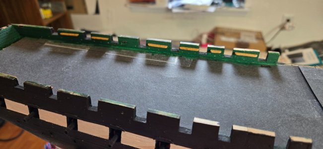
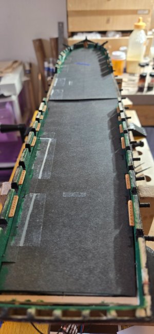
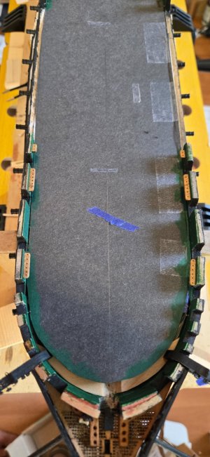
The black card stock is just to keep saw dust etc from getting down on the gun deck while I work on the bulwarks. While I was at it, I went ahead and drilled out all the holes for the eyebolts for gun tackle. Of course this made me realize that I need to make up 20 "double" eyebolts. On the gun deck I made these by looping a piece of wire around two closely space pins. This time I think I might try Mustafa's method of making two loops and then folding them to come together. We'll see. Everything is different at this scale. I've decided that like the gun deck, I'm only going to install the training tackle on the carronades and not the inhaul tackle. To put everything in would just look too cluttered.
The black card stock is just to keep saw dust etc from getting down on the gun deck while I work on the bulwarks. While I was at it, I went ahead and drilled out all the holes for the eyebolts for gun tackle. Of course this made me realize that I need to make up 20 "double" eyebolts. On the gun deck I made these by looping a piece of wire around two closely space pins. This time I think I might try Mustafa's method of making two loops and then folding them to come together. We'll see. Everything is different at this scale. I've decided that like the gun deck, I'm only going to install the training tackle on the carronades and not the inhaul tackle. To put everything in would just look too cluttered.
I believe I employed Mustafa's technique to make the double eyebolts. Actually, I also now make my own single eye bolts using a pointy needle nose pliers as well.
pleasant memories, to be sure.
Have fun.
pleasant memories, to be sure.
Have fun.
Peter, I too tried making my own single eyebolts because the ones supplied by BJ are way oversized, but found something much better. Fish hooks. They come in so many different sizes that you can get exactly what you need. You just cut the eye off the end of the hook. You can buy them dirt cheap from China. I actually cut 75 today in about 30 minutes in preparation for rigging the carronades. And, they can be purchased with a black finish.
Easy peasy.
Easy peasy.
Ach du Lieber! Now why didn't I think of that!!
Well I still have to do a few more, so it's not too late to learn something new.
Well I still have to do a few more, so it's not too late to learn something new.
With all the pin rails finished and in place I was ready to move on to the other bulwark details starting with the cleats. The kit supplies 8 large (5/16") cleats made from Brittania metal. I decided to make these out of wood for a much better look. The Navy plans for these cleats (Plan #28433) gives al the dimensions. They are essentially 8.5" square and 47.5" long and shaped accordingly. I saw three ways of shaping these. First was to use square stock, cut to length and file/sand away the bottom half on each end to make the cleat. I didn't like this as I saw it being difficult to reproduce exactly several times. The next would be to sandwich two thinner pieces of different lengths to make the shape of the cleat. Although this seemed to be a bit more reproduceable, it also seemed like a lot of fiddy work. I finally decided the best approach would be to use a piece of flat stock that was 0.5"x.090" and run it edgewise through the Byrnes saw with the depth set appropriately to trim off the bottom half on either side. This gave me the shape of the cleat which I could then slice off like bread using the chop saw
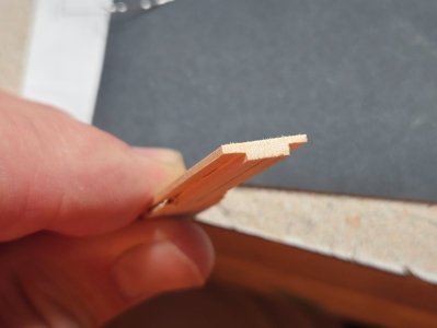
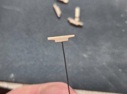
Once cut, I drilled a hole in the center for a pin. A little stain and some black dots for the other "bolts" and they were done
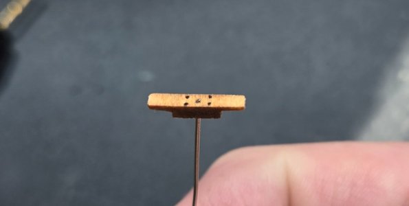
Here's where i ran into some trouble. The BJ instructions once again proved to be a source of frustration. The actual instructions for the spar deck construction make no mention of any cleats. The belaying plan in the back of the book do mention cleats, but with little detail and I believe some missing information. here is the plan
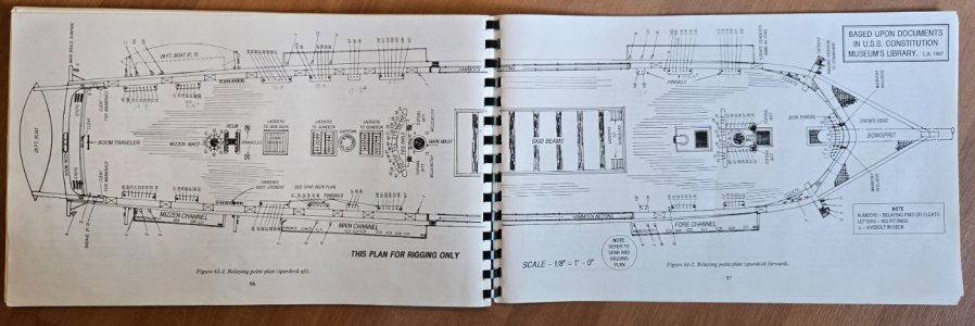
The first thing to mention is the note in the far right corner. It states that numbers = belaying pins or cleats. As far as I can see all the numbers on this diagram point to pin rails. No cleats. Next, if we look closer at the bow, it does mention cleats, but provides no details
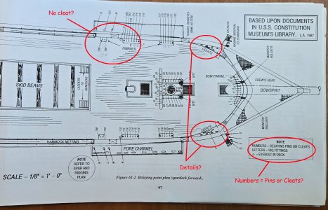
Although it clearly shows some different sized cleats, the larger of course being the large wooden cleat. It only shows four small cleats, whereas there are 5 0n the actual ship. Three wooden ones that appear to be slightly larger than the two iron ones close to the cathead. The kit provides two sizes of small photo etched brass cleats. For now, I am going to assume that the one directly above the cathead was simply omitted in the drawing and that there are five smaller cleats here. As we move aft, you can see that there is no mention of the large wooden cleat that is currently just forward of the waist. Again, I am going to presume that this large cleat should be here.
Looking at the aft end of the plan, there are more missing details
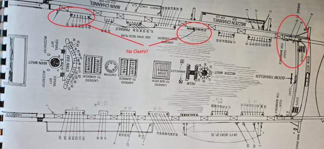
You can see that there is no mention of the large wooden cleats currently just aft of the waist and just in front of the davit just forward of the mizzen channel. As we get to the transom, there is again mention of some cleats. The apparent size of the cleats is similar to the large cleats on the bow, however, the ones currently on the ship are the smaller wooden ones. I guess I will assume that the ones drawn here simply aren't meant to be to scale. In addition to that, the diagram indicates an eyebolt in the deck for the gaff vangs (denoted "B" inside the red circle). The ship currently has cleats in the corner of the transom, and interestingly, the Revell model shows those cleats present and intended for the gaff vangs. Seems to me that a cleat would be more appropriate for this tie off?
Lastly, there is the cleat indicated in the center of the transom, aft of the boom traveler. Currently, this cleat appears to be in the deck forward of the traveler, perhaps because of the gunport there now. Regardless, there once again is no indication of the size of this cleat, although looking at the real ship, it appears to be one of the smaller iron ones.
I guess at this point, I am going to use the current ship for guidance and position the cleats as they are on the ship now, although I would welcome any comments from those of you who might know better. One last detail, there are 8 of the large cleats provided in the kit. If we take into account the ones missing in the diagram above, there would be 8 needed.
Once cut, I drilled a hole in the center for a pin. A little stain and some black dots for the other "bolts" and they were done
Here's where i ran into some trouble. The BJ instructions once again proved to be a source of frustration. The actual instructions for the spar deck construction make no mention of any cleats. The belaying plan in the back of the book do mention cleats, but with little detail and I believe some missing information. here is the plan
The first thing to mention is the note in the far right corner. It states that numbers = belaying pins or cleats. As far as I can see all the numbers on this diagram point to pin rails. No cleats. Next, if we look closer at the bow, it does mention cleats, but provides no details
Although it clearly shows some different sized cleats, the larger of course being the large wooden cleat. It only shows four small cleats, whereas there are 5 0n the actual ship. Three wooden ones that appear to be slightly larger than the two iron ones close to the cathead. The kit provides two sizes of small photo etched brass cleats. For now, I am going to assume that the one directly above the cathead was simply omitted in the drawing and that there are five smaller cleats here. As we move aft, you can see that there is no mention of the large wooden cleat that is currently just forward of the waist. Again, I am going to presume that this large cleat should be here.
Looking at the aft end of the plan, there are more missing details
You can see that there is no mention of the large wooden cleats currently just aft of the waist and just in front of the davit just forward of the mizzen channel. As we get to the transom, there is again mention of some cleats. The apparent size of the cleats is similar to the large cleats on the bow, however, the ones currently on the ship are the smaller wooden ones. I guess I will assume that the ones drawn here simply aren't meant to be to scale. In addition to that, the diagram indicates an eyebolt in the deck for the gaff vangs (denoted "B" inside the red circle). The ship currently has cleats in the corner of the transom, and interestingly, the Revell model shows those cleats present and intended for the gaff vangs. Seems to me that a cleat would be more appropriate for this tie off?
Lastly, there is the cleat indicated in the center of the transom, aft of the boom traveler. Currently, this cleat appears to be in the deck forward of the traveler, perhaps because of the gunport there now. Regardless, there once again is no indication of the size of this cleat, although looking at the real ship, it appears to be one of the smaller iron ones.
I guess at this point, I am going to use the current ship for guidance and position the cleats as they are on the ship now, although I would welcome any comments from those of you who might know better. One last detail, there are 8 of the large cleats provided in the kit. If we take into account the ones missing in the diagram above, there would be 8 needed.
I'm sure Jon will chime in with the appropriate photos. My 2 cent's worth? Nicely done!


Nice job so far!Hello All,
Another victim here of the MSW disaster. Two and a half years into my build and sadly, I did not keep a personal copy of my log. So, instead of trying to re-do the entire thing from the beginning, I am going to start up my log from where I am. As it stands, I am just getting started on the spar deck. Here are a few photos of the ship currently
View attachment 596698 View attachment 596699
View attachment 596705
View attachment 596704
Welcome aboard. Looking forward to following your build log.