USS Constitution Cross Section - Model Shipways MS20245 - 1:76 - by JeffT [COMPLETED BUILD]

Joined
Sep 1, 2020
Messages
811
Points
353

Location
Cicero, NY
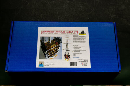
This new build is of the Model Shipways USS Constitution Cross Section (MS2045) at 1:76 (Actually the scale is 1:76.8 or 5/32" = 1'). The finished model is 4"x6"x32". I chose this kit for several reasons: 1) It is a nice kit and I like cross sections; 2) The Constitution cross section is a preliminary to my next build; and 3) I was able to purchase the kit from Model Expo for a very good price during one of their sales.

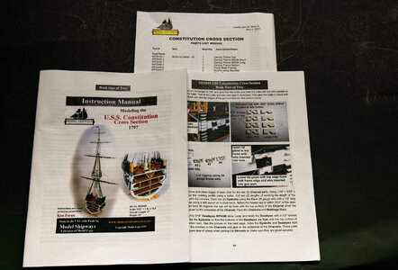
I was not able to find another example of this kit on SOS so I will present the kit contents in this post. The box is the typical Model Shipways blue box, but significantly shorter than most of their kits. The detailed instruction booklets are quite good with 2 booklets of 96 pages total. Relatively clear instructions with lots of pictures.
IMG_7533.jpg
IMG_7534.jpg

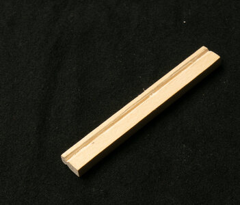
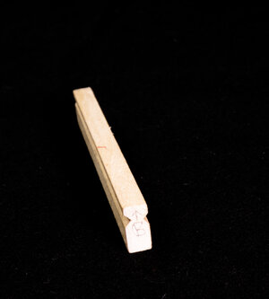
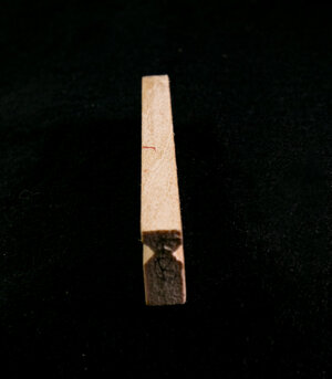
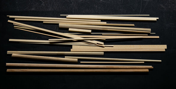
The wood is typical MS quality which is good. There is a bag of pieces of square, rectangular, and round stock.
IMG_7537.jpg

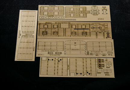
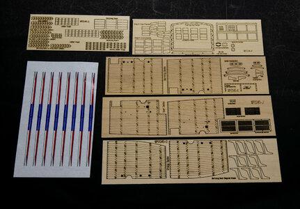
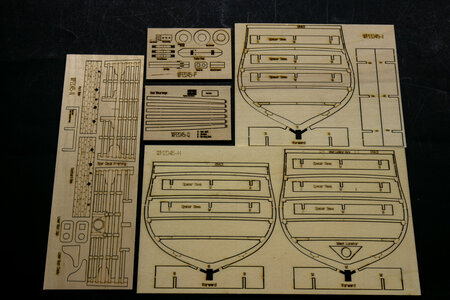
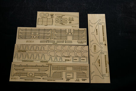
The laser cut wood is of various thickness and the cutting is good for the most part. The parts can easily be cut out and there are a minimal number of hold points to cut.

IMG_7539.jpg
IMG_7541.jpgIMG_7542.jpgIMG_7543.jpg


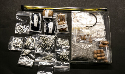
The metal parts are mainly Britannia metal with some brass strips of the typical MS quality which I rate as acceptable, but not the best quality. There are significant amounts of mold flashing to remove from some of the pieces and they are covered with a dull substance which needs to be removed before painting. The rigging thread is MS' nylon and will not be used. I am accumulating a lot of MS rigging line in a box.
IMG_7536.jpg
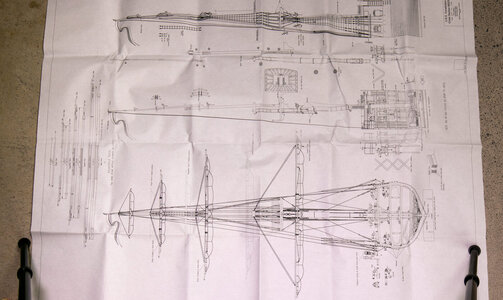
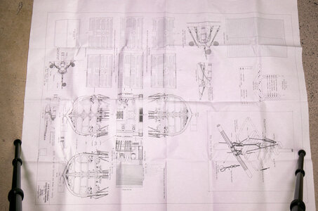
The 2 sheets of plans are large and easy to read. There are also 3 sheets of plans that show the individual parts and their locations on the laser cut pieces. IMG_7544.jpg
IMG_7545.jpg


I have already been working on this kit since I finished my last build (Bluenose by MS). As seems typical for me, I get going on a new build taking pictures as I go along, but don't get around to starting a log until I am well into the build. I will be catching up over the next month or so. I am using one particular build log on MSW (USS Constitution cross section by TomCulb - FINISHED - Model Shipways - 1:76.8) as a reference and to see where the problems lie with this kit.

One thing that I have noticed is that having a downloaded version of the instruction manual on a tablet or computer has been very helpful. The printed manual's pictures are small, a bit dark and not very high resolution. On a tablet they are brighter and of higher resolution so you can zoom in to look at details you cannot see in the printed version.

Edit 30Jan2024
Note to future builders of this kit: MS supplies 10 sets of upper and lower chainplates with the kit. The rigging plans and pictures clearly show that there are 5 deadeyes per side so 10 seems correct. However, there is also a eyebolt required on the channel. This eyebolt is connected to the hull using the same upper and lower chainplates. Model Expo is very good about making good on missing or damaged items in their kits, so I placed a (cost free) order for more chainplates. I suggest that you do this early in the build so that you have them when you reach this point in the build.
 
Last edited:
This new build is of the Model Shipways USS Constitution Cross Section (MS2045) at 1:76 (Actually the scale is 1:76.8 or 5/32" = 1'). The finished model is 4"x6"x32". I chose this kit for several reasons: 1) It is a nice kit and I like cross sections; 2) The Constitution cross section is a preliminary to my next build; and 3) I was able to purchase the kit from Model Expo for a very good price during one of their sales.

I was not able to find another example of this kit on SOS so I will present the kit contents in this post. The box is the typical Model Shipways blue box, but significantly shorter than most of their kits. The detailed instruction booklets are quite good with 2 booklets of 96 pages total. Relatively clear instructions with lots of pictures.
View attachment 399620
View attachment 399621

The wood is typical MS quality which is good. There is a bag of pieces of square, rectangular, and round stock.
View attachment 399623

The laser cut wood is of various thickness and the cutting is good for the most part. The parts can easily be cut out and there are a minimal number of hold points to cut.
View attachment 399624
View attachment 399625View attachment 399626View attachment 399627


The metal parts are mainly Britannia metal with some brass strips of the typical MS quality which I rate as acceptable, but not the best quality. There are significant amounts of mold flashing to remove from some of the pieces and they are covered with a dull substance which needs to be removed before painting. The rigging thread is MS' nylon and will not be used. I am accumulating a lot of MS rigging line in a box.
View attachment 399622
The 2 sheets of plans are large and easy to read. There are also 3 sheets of plans that show the individual parts and their locations on the laser cut pieces. View attachment 399628
View attachment 399629


I have already been working on this kit since I finished my last build (Bluenose by MS). As seems typical for me, I get going on a new build taking pictures as I go along, but don't get around to starting a log until I am well into the build. I will be catching up over the next month or so. I am using one particular build log on MSW (USS Constitution cross section by TomCulb - FINISHED - Model Shipways - 1:76.8) as a reference and to see where the problems lie with this kit.

One thing that I have noticed is that having a downloaded version of the instruction manual on a tablet or computer has been very helpful. The printed manual's pictures are small, a bit dark and not very high resolution. On a tablet they are brighter and of higher resolution so you can zoom in to look at details you cannot see in the printed version.
Good morning Jeff. This is awesome. I will pull up a chair. Cheers Grant
 
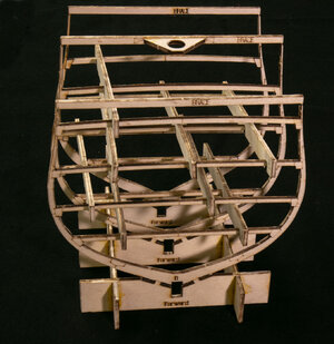
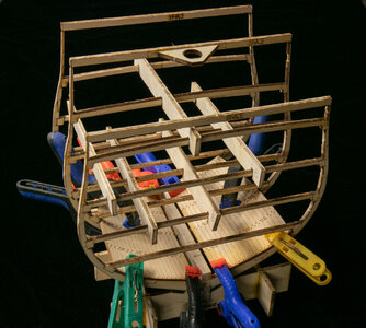
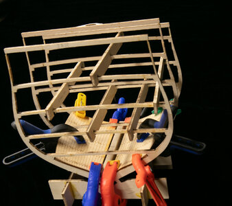
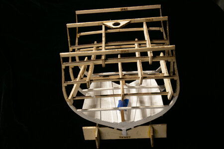
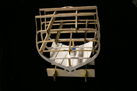
The frame for the Constitution cross section consists of three bulkheads with an integral working base and braces at the top to keep everything in alignment. The middle side to side piece has a piece to help center the mast correctly. Moveable braces are used fore and aft to further aid in maintaining alignment of the frames as you build upwards from the hold. The upperparts of the frames are extremely thin and fragile. (I will address this in a later posting as I broke them all during various parts of the construction process.)
IMG_7552.jpg


Once the frame is constructed, a rabbet is cut into the keel piece and the keel is glues in place in the slot that is part of the base.
IMG_7554.jpgIMG_7555.jpgIMG_7558.jpg
 
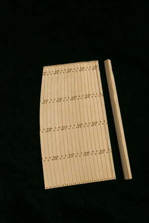
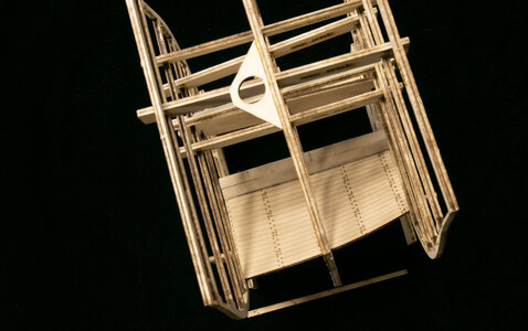
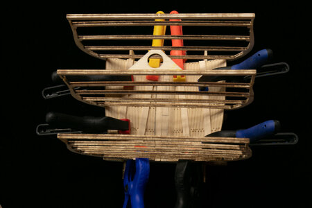
The keel is slip into the build frame and glued in place to the bulkheads, not the build frame. The decking planking for each deck is pre-cut and nicely scribed as laser cut pieces. The hold decking was moistened, clamped to the frames and allowed to dry in place.
IMG_7560.jpg
IMG_7562.jpg
Limber flats (pieces placed along the keel) are shaped to fit next to the keel. These take some effort to get into the correct shape per the plans. I found it easier to make the "steps" for the mast foot separately and then glue them in place on the limbers. The instructions have you shape these steps directly into the limbers. The deck planking pieces were marked and cut down to fit the limbers that I made.
IMG_7565.jpg


Port side of the deck planking and limber installed. The starboard was similar.
IMG_7563.jpg
 
So in your opinion, would there be more frames between the ones represented?

If so, then treenail would need to be added where the deck crossed each frame.

This is something many model companies fail to understand, that a plank or deck board is fastened to every frame piece not just the ones shown up topside.
According to drawings in Marquardt's Anatomy of the Ship: The 44-Gun Frigate USS Constitution "Old Ironsides", there are at least 5 doubled and 4 single width frames between the area spanned by the model. Neither the deck pieces nor the outer sidewalls reflect that number of rows of nails.
 
That issue is why I dislike planking with nails already added. It is hard to add new nail holes that match, and hard not having all the needed rows represented.
 
The hold decking and diagonal braces have been installed and painted white. The blue tape is covering the mast hole for the next step. Some bending is required to get the correct shape to the decking and the braces. Note the use of spacers to keep the frames spaced correctly during the build.
IMG_7567.jpg
IMG_7568.jpg

IMG_7569.jpg
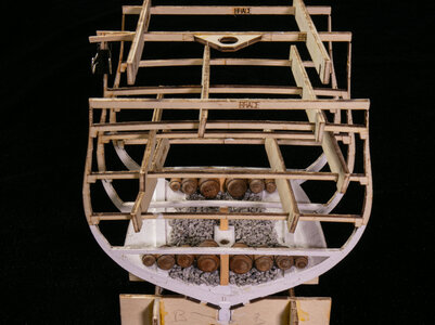
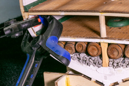
The kit includes "gravel" for ballast in the hold. The posts were fashioned, painted and glued in place next. Following the instructions, I soaked the gravel in a 50/50 mix of white glue /water to thoroughly coat it with glue and placed it into the hold area. I used some tape at the ends to keep the gravel in place while it was drying and tape over the mast hole to keep gravel out of it. Once dry, I added the barrels to the hold. Barrel rings were blacked with a fine point Sharpie.
IMG_7577.jpg
 
The hold decking and diagonal braces have been installed and painted white. The blue tape is covering the mast hole for the next step. Some bending is required to get the correct shape to the decking and the braces. Note the use of spacers to keep the frames spaced correctly during the build.
View attachment 404191
View attachment 404192

View attachment 404193
The kit includes "gravel" for ballast in the hold. The posts were fashioned, painted and glued in place next. Following the instructions, I soaked the gravel in a 50/50 mix of white glue /water to thoroughly coat it with glue and placed it into the hold area. I used some tape at the ends to keep the gravel in place while it was drying and tape over the mast hole to keep gravel out of it. Once dry, I added the barrels to the hold. Barrel rings were blacked with a fine point Sharpie.
View attachment 404194
Good morning Jeff. Looking splendid. Cheers Grant
 
Very impressive build to date. I wish I remembered more of my visit 20 years ago or so.
It's been around 20 years since I was there as well. I have been to Portsmouth to see the Victory in the past 8 years or so (see my avatar). Boston is only about a 5 hour drive away, so I should go visit again. When I was working, I probably went to the Boston area about 6-8 times per year, but never seemed to have time to make a trip to the ship.
 
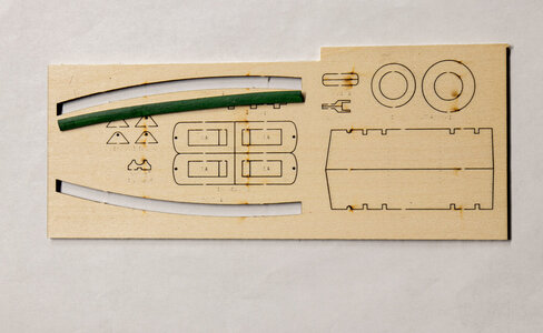
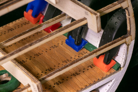
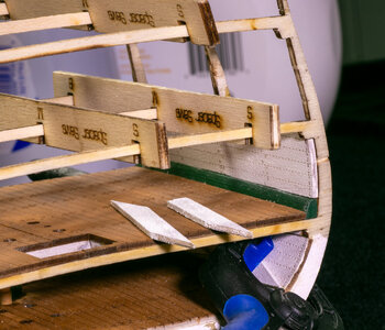
The waterways for the orlop deck are installed next. These are laser cut pieces with a curve. The curve did not match the curve of my hull, so I soaked them in hot water and bent them to fit the curve by clamping in place after soaking. The first photo shows the difference in the curve as supplied and the final curve I needed.
IMG_7579.jpg

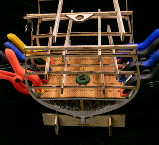
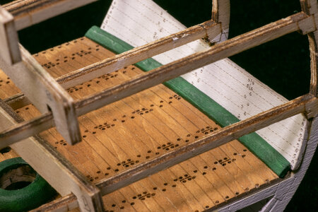
The waterways were painted green and glued into place. I also installed the mast surround for the orlop deck. The sidewalls were also painted and installed but I didn't take any pictures of that step.
IMG_7580.jpgIMG_7582.jpgIMG_7584.jpg


I forget to mention in the previous point something you can see in the second picture. You will note the clamp and "splint" on the middle brace and the bulwarks extension. I broke this connection at some point handling the hull. I am hoping this won't be a problem since the mast guide is important for getting the proper slant to the mast.
 
Installation of the orlop deck diagonals.

After installing the berthing deck and its sidewalls. I cut, painted and glued in the diagonal along the orlop deck sidewalls. You can see how the waterways on the berthing and gun decks fit in these photos as well.
IMG_7586.jpgIMG_7587.jpg
 
Back
Top