Good morning Jeff. Looking good. I love the detail in the close up pics. Cheers grantInstallation of the orlop deck diagonals.
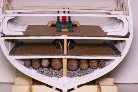
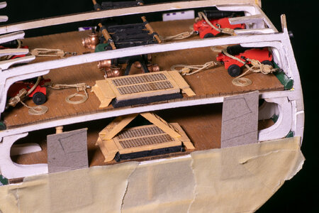
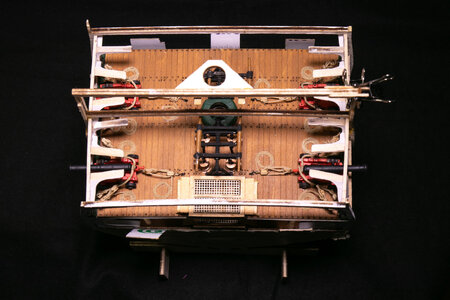
After installing the berthing deck and its sidewalls. I cut, painted and glued in the diagonal along the orlop deck sidewalls. You can see how the waterways on the berthing and gun decks fit in these photos as well.
View attachment 405129View attachment 405130
You are using an out of date browser. It may not display this or other websites correctly.
You should upgrade or use an alternative browser.
You should upgrade or use an alternative browser.
USS Constitution Cross Section - Model Shipways MS20245 - 1:76 - by JeffT [COMPLETED BUILD]
I painted the laser cut knees while still attached to the backbone. After painting the flat portion, I removed them, sanded off the laser cutting debris and painted the edges that were not going to be glued. Three types of knees are needed on the berthing deck: standing, hanging and diagonal braces. I glued them in place with wood glue. Some additional painting was needed after the glue dried. I got better at this as I proceeded with the knees.
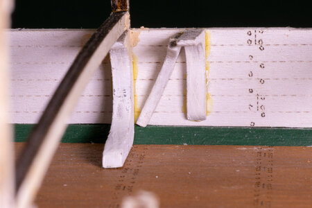
The standing knees need to be adjusted a bit to fit the waterway but fit well for the most part. The diagonal braces need to be fit to both the standing and the hang knees and are a bit more difficult to form correctly.
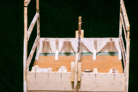
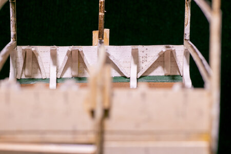
As you might have noticed, I have completely broken off the middle brace at this point. I am going to leave it off until I need it in the future. If I break off the others while constructing the model, I am not going to try to fix them until necessary. I did add some support to what is left of the middle brace as I need this much for the gun deck installation.

The standing knees need to be adjusted a bit to fit the waterway but fit well for the most part. The diagonal braces need to be fit to both the standing and the hang knees and are a bit more difficult to form correctly.


As you might have noticed, I have completely broken off the middle brace at this point. I am going to leave it off until I need it in the future. If I break off the others while constructing the model, I am not going to try to fix them until necessary. I did add some support to what is left of the middle brace as I need this much for the gun deck installation.
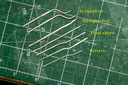
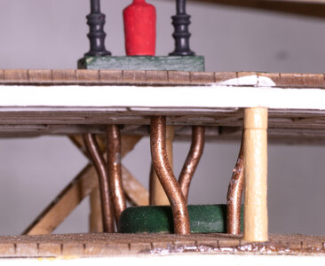
My next project for the build was the pipes for the pumps. These are supplied as Britannia metal. As supplied the bend in the parts is too extreme to mount correctly. I first made a pattern piece out of aluminum rod by fitting it to each of the 6 places where the pipes pass through the decks. The supplied pieces were straightened and re-bent to fit correctly.
The instructions describe gluing the upper parts with the lower parts, but I took a simpler approach and cut the pipes to fit into the collars so the joint would be hidden. Pipes were painted copper and glued in place. The double pump body was painted and installed as were the collars for the single pump forward of the mast.
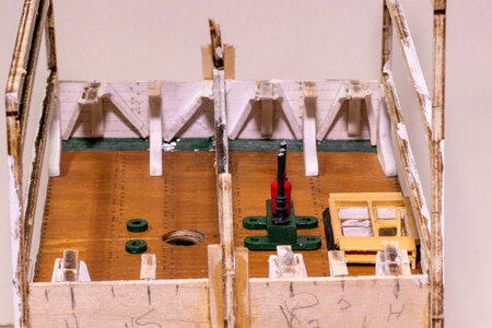

I taped of the lower 2 openings to avoid getting dust in these areas while constructing the upper parts of the model. I latter took off the tape and added some thin cardboard over the posts and retaped. The cardboard helps keep me from pushing the posts out the place while working on the model. Posts were shaped using a mini lathe.
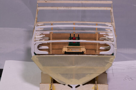
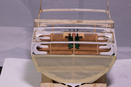

The instructions describe gluing the upper parts with the lower parts, but I took a simpler approach and cut the pipes to fit into the collars so the joint would be hidden. Pipes were painted copper and glued in place. The double pump body was painted and installed as were the collars for the single pump forward of the mast.


I taped of the lower 2 openings to avoid getting dust in these areas while constructing the upper parts of the model. I latter took off the tape and added some thin cardboard over the posts and retaped. The cardboard helps keep me from pushing the posts out the place while working on the model. Posts were shaped using a mini lathe.


Good morning Jeff. Awesome. The detail is wonderful and I love how realistic the copper pipes look. Cheers GrantMy next project for the build was the pipes for the pumps. These are supplied as Britannia metal. As supplied the bend in the parts is too extreme to mount correctly. I first made a pattern piece out of aluminum rod by fitting it to each of the 6 places where the pipes pass through the decks. The supplied pieces were straightened and re-bent to fit correctly.
View attachment 408470
The instructions describe gluing the upper parts with the lower parts, but I took a simpler approach and cut the pipes to fit into the collars so the joint would be hidden. Pipes were painted copper and glued in place. The double pump body was painted and installed as were the collars for the single pump forward of the mast.
View attachment 408471View attachment 408472View attachment 408473View attachment 408472
I taped of the lower 2 openings to avoid getting dust in these areas while constructing the upper parts of the model. I latter took off the tape and added some thin cardboard over the posts and retaped. The cardboard helps keep me from pushing the posts out the place while working on the model. Posts were shaped using a mini lathe.
View attachment 408474View attachment 408476
Thanks, Grant. I did the pipes with some acrylic paint first, but they just didn't seem right, so I removed it and used some enamel paint that I kept from building a plastic ship model over 20 years before. I was surprised the paint was still good. The enamel looked much better in this case.Good morning Jeff. Awesome. The detail is wonderful and I love how realistic the copper pipes look. Cheers Grant
Moving up another level to the gun deck. The deck framing and waterways were installed in a similar manner to the other decks. The 2 decking was then stained and glued in pace. The sidewalls were painted white on the inner surface and the gun breaching rope eyebolts were installed. The build requires some double eyebolts for the gun training tackle. These were made following the description in the instructions. Hopefully pictures of the double eyebolts will be seen in future pictures in the log, as I didn't take any after their installation.
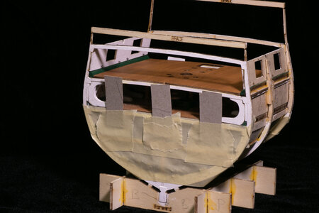
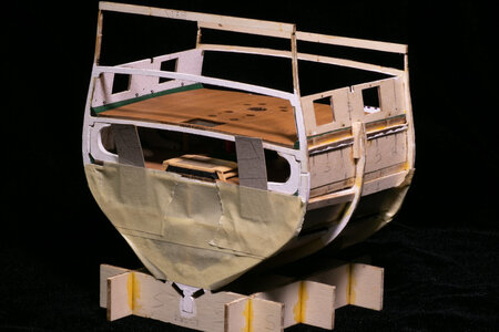
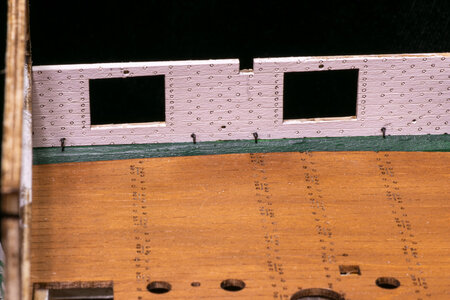
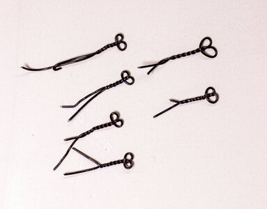


Hi Jeff looks great a huge amount of detail in a small space.Moving up another level to the gun deck. The deck framing and waterways were installed in a similar manner to the other decks. The 2 decking was then stained and glued in pace. The sidewalls were painted white on the inner surface and the gun breaching rope eyebolts were installed. The build requires some double eyebolts for the gun training tackle. These were made following the description in the instructions. Hopefully pictures of the double eyebolts will be seen in future pictures in the log, as I didn't take any after their installation.
View attachment 409145View attachment 409146View attachment 409147View attachment 409148View attachment 409149
Tony
I have the guns for the gun deck completed at this point. I build the carriages as described in the instructions. I drilled out the barrels of the metal cannon some as the barrel was very much undersized. I may have gone a bit too far, however.
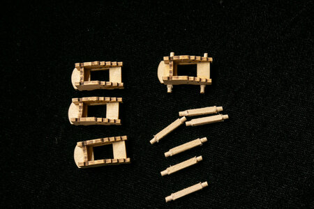
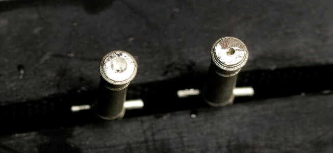
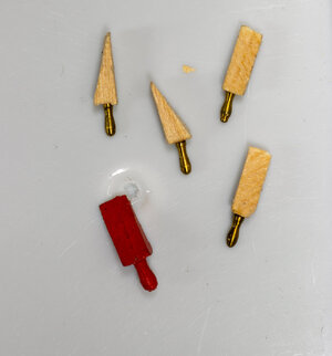
I felt the quoins were oversized as supplied, so I made new ones using some small brass belaying pins that I had in my stash of supplies. The painted one is the original kit supplied version.
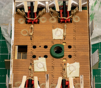
The guns were rigged, and rope coils were added. The tops of 2 of the pumps and the mast ring were installed after the guns were rigged. The guns still need a bit of alignment.
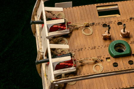
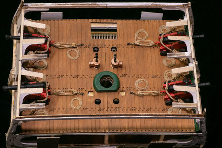


I felt the quoins were oversized as supplied, so I made new ones using some small brass belaying pins that I had in my stash of supplies. The painted one is the original kit supplied version.

The guns were rigged, and rope coils were added. The tops of 2 of the pumps and the mast ring were installed after the guns were rigged. The guns still need a bit of alignment.


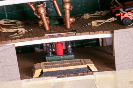
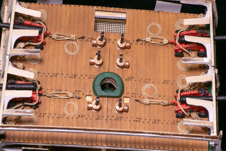
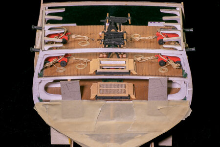
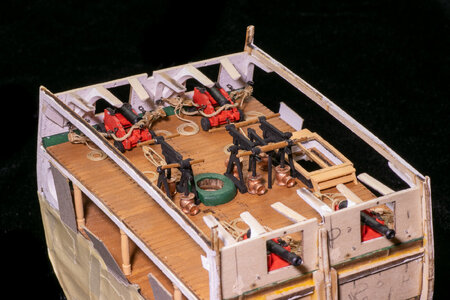
More pictures of knees and gun deck fittings. The pumps were difficult to figure out just how to put them together and they were initially too high for the spar deck. I had to file them down to get the height down to fit under the deck above. You can get some nice views of how much I have broken off the upper deck supports.
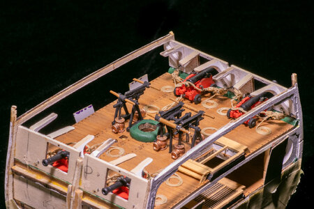
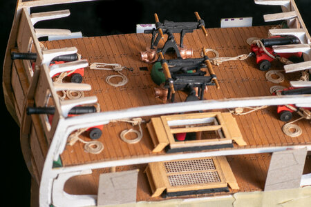


Good morning Jeff. With all those details and cannons she is becoming a classic cross section- looking really good. Cheers GrantMore pictures of knees and gun deck fittings. The pumps were difficult to figure out just how to put them together and they were initially too high for the spar deck. I had to file them down to get the height down to fit under the deck above. You can get some nice views of how much I have broken off the upper deck supports.
View attachment 414101View attachment 414102View attachment 414103View attachment 414104View attachment 414105View attachment 414106
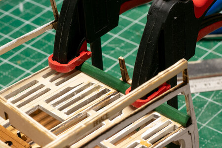
Time to start addressing the broken upper bulwark extensions. I created some "splints" for the center one on both sides first. You can see the break in between the splints. The upper part is held in place with clamps and splints until the spar deck is glued in place.
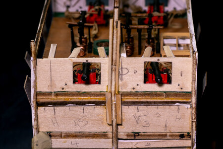
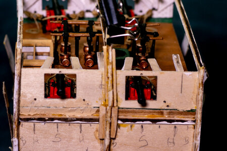
Once the frames and the spar deck were completed the waterways were carved, painted and glued. At this point I made the final repairs to the bulwark extensions using some 1/16-inch basswood. The height above the deck was based on the height of the bulwark sides. As long as I was making repairs, I made the extensions much wider than the original ones for additional support and gluing surface (checking first to make sure I was not interfering with the gun ports in the sidewalls).
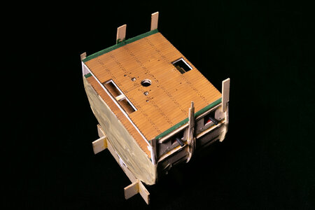
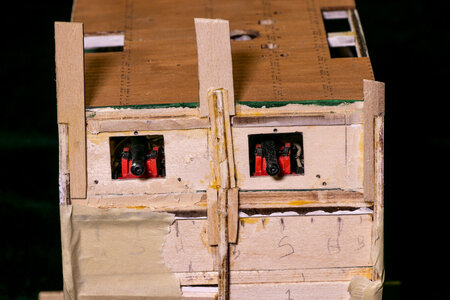
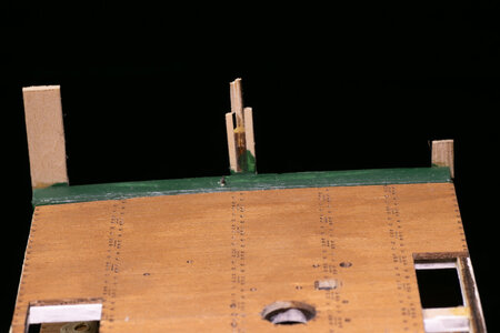
I am pleased with the fixes to the extensions. It was much easier to work on adding items to the decks without the upper parts of the build frames in the way. I might go so far as to suggest that other builders of this kit remove them (in a more controlled manner than breaking them at odd places) so as to make the building go more easily. The fix turned out to be quite easy (and looking ahead a step or two worked out well). Some minor bending will be required to match the slight tumblehome but the support on both sides (bulwarks and sidewalls) will take care of that without much need to carefully bend the new extensions.


Once the frames and the spar deck were completed the waterways were carved, painted and glued. At this point I made the final repairs to the bulwark extensions using some 1/16-inch basswood. The height above the deck was based on the height of the bulwark sides. As long as I was making repairs, I made the extensions much wider than the original ones for additional support and gluing surface (checking first to make sure I was not interfering with the gun ports in the sidewalls).


I am pleased with the fixes to the extensions. It was much easier to work on adding items to the decks without the upper parts of the build frames in the way. I might go so far as to suggest that other builders of this kit remove them (in a more controlled manner than breaking them at odd places) so as to make the building go more easily. The fix turned out to be quite easy (and looking ahead a step or two worked out well). Some minor bending will be required to match the slight tumblehome but the support on both sides (bulwarks and sidewalls) will take care of that without much need to carefully bend the new extensions.
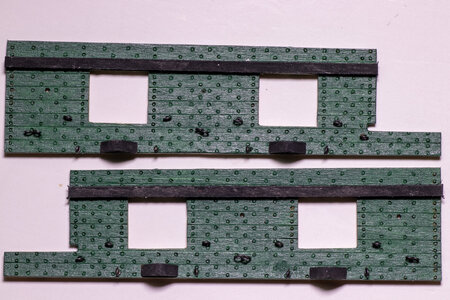
I have progressed to making the bulwarks for the model. These are fairly straightforward since they are laser cut pieces. They required painting them green, placing black strips of wood above the gum ports, adding eyebolts and the mounting pieces for the guns.
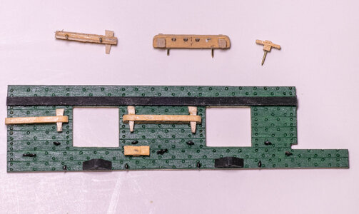
Next the pin rails and a cleat were added.
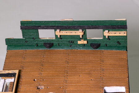
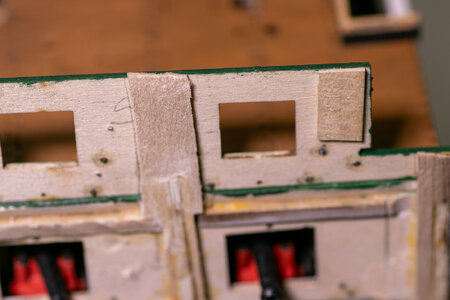
Once the inner bulwarks in place, I added some pieces to reinforce where the inner bulwarks and outer sidewalls would meet.
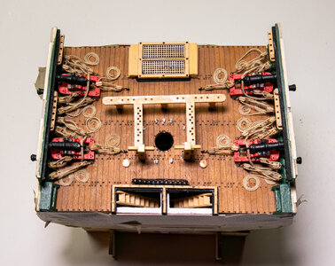
Gratings, support columns, ladders, and steps were built in the same manner as the gun deck.
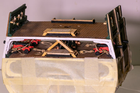
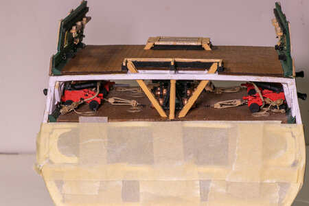
Finally, the 4 carronades were rigged, eyebolts added around the mast, boarding steps built/painted/installed, and cannon balls placed in their frame.
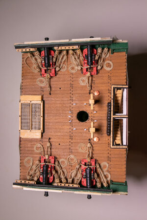

Next the pin rails and a cleat were added.


Once the inner bulwarks in place, I added some pieces to reinforce where the inner bulwarks and outer sidewalls would meet.

Gratings, support columns, ladders, and steps were built in the same manner as the gun deck.


Finally, the 4 carronades were rigged, eyebolts added around the mast, boarding steps built/painted/installed, and cannon balls placed in their frame.

I added the belaying pin rail around the mast. You cannot see them here , but the supports for the rail are difficult to work with and require patience. I also sanded off the area for the top rail on each side.
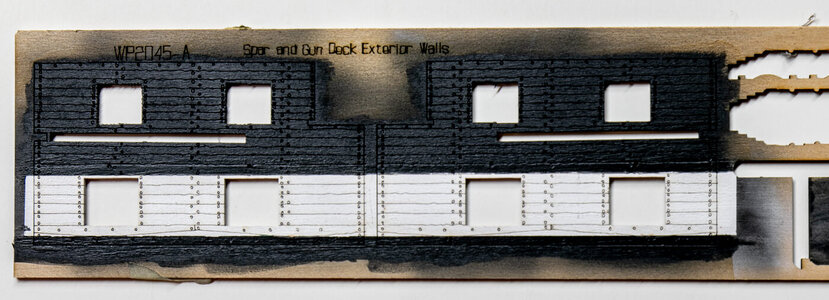
The walls are my next sub-project. I spray painted the laser cut parts before removing them. They are painted with one white stipe and two black stripes.
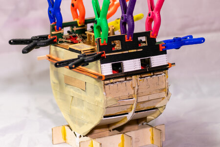
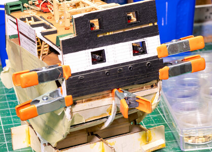
The sides were attached with lots of clamps and a few rubber bands.
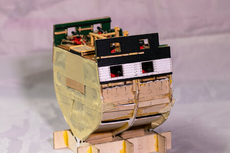
Next I painted and added the strake to the side along with the metal hardware.
I am just about ready to plank the lower part of the hull. This should go fairly easily since it's only 4 inches wide. I have to figure out what I am going to use for some of the planking because the kit does not supply as much as is needed.
If anyone has any ideas about how to make bright brass belaying pins look like wood, I would be very interested. I don't want to blacken then.

The walls are my next sub-project. I spray painted the laser cut parts before removing them. They are painted with one white stipe and two black stripes.

The sides were attached with lots of clamps and a few rubber bands.


Next I painted and added the strake to the side along with the metal hardware.

I am just about ready to plank the lower part of the hull. This should go fairly easily since it's only 4 inches wide. I have to figure out what I am going to use for some of the planking because the kit does not supply as much as is needed.
If anyone has any ideas about how to make bright brass belaying pins look like wood, I would be very interested. I don't want to blacken then.
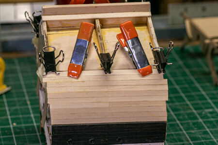
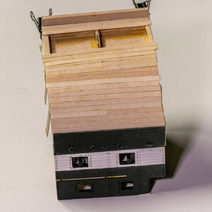
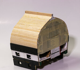
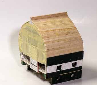
Planking the cross section of the Constitution is not difficult. The only issue that I had was that it was obvious that the amount of wood supplied for the planking was not going to be sufficient to complete the full planking. The supplied strips are 12" long and would have been enough if the lengths needed were 4", but they actual length was about 4 1/8" so I could only get 2 planks from each full length strip. I gain some by using 2 half-length pieces where I could, but I still came up needing to find some final planks from leftovers from other builds. This was not a big problem, but it did require some thought. There is some adjustment required for a couple of strips to match the change in width of the model from bow to stern. Only 2 strips required shaping. Minimal filling will be needed and sanding should go quickly.


Last edited:
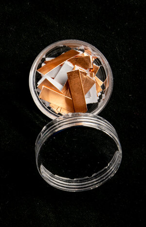
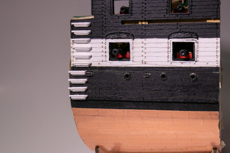
With the planking and sanding completed, it was time to move to the coppering of the hull. I have been apprehensive about coppering for a while, so I read lots of ways to do this before starting. The kit provides copper tape for the task as well as some very detailed information on how to use the tape. I chose to use a different method that while probably taking longer, it seemed easier to me. I cut the tape into individual "plates" at the length that was appropriate for the kit (about 2.2 cm). I choose not to add nail heads to the plates. The decision was based on the scale of the model and (more importantly) the skill of the modeler.
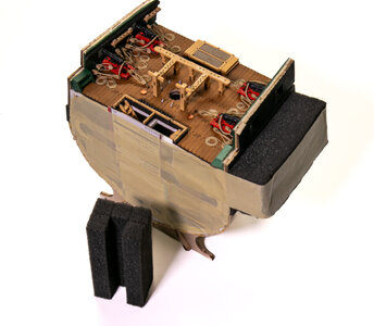
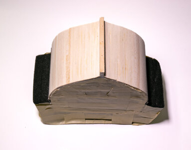
I used some foam strips to create covers for the channels so that I could lay the hull on its side while planking near the top of the coppered area.
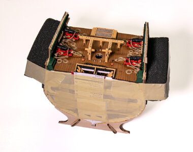
Starting at the keel, I plated upwards (although it felt like upwards considering the hull was upside down) alternately using 5 full plates or 4 full plates and 2 half plates per row. The plates were laid from stern to bow so that the overlap was in the appropriate direction. Once I got to the correct number of rows placed (per the plans), I used a row of partial plates cut diagonally to correct for the curve of the hull. 3 additional rows were added to complete the planking of the sides. The keel was coppered after the first couple of rows of hull plating had been applied.
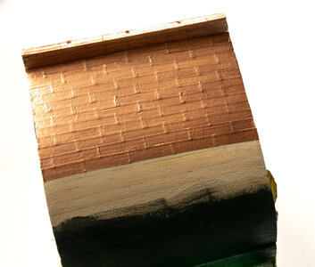
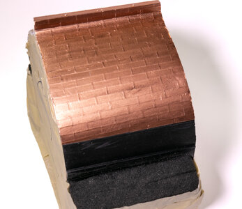
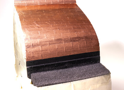
The coppering was not perfect, but I learned a lot about how much pressure to apply and what tools worked reasonably well to smooth out the plates without damaging them. A wide pencil eraser seemed to work especially well. I am happy that task has been completed.

I used some foam strips to create covers for the channels so that I could lay the hull on its side while planking near the top of the coppered area.


Starting at the keel, I plated upwards (although it felt like upwards considering the hull was upside down) alternately using 5 full plates or 4 full plates and 2 half plates per row. The plates were laid from stern to bow so that the overlap was in the appropriate direction. Once I got to the correct number of rows placed (per the plans), I used a row of partial plates cut diagonally to correct for the curve of the hull. 3 additional rows were added to complete the planking of the sides. The keel was coppered after the first couple of rows of hull plating had been applied.


The coppering was not perfect, but I learned a lot about how much pressure to apply and what tools worked reasonably well to smooth out the plates without damaging them. A wide pencil eraser seemed to work especially well. I am happy that task has been completed.
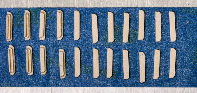
Next - Board Steps. The steps were made in 3 parts held down to tape to keep them from moving all over my work surface. The picture shows the steps in the stages of building them. Once painted they were glued to the sides of the hull on both sides. I also added the "eyebrow" decorations above the gun deck gun ports.


Hi JeffWith the planking and sanding completed, it was time to move to the coppering of the hull. I have been apprehensive about coppering for a while, so I read lots of ways to do this before starting. The kit provides copper tape for the task as well as some very detailed information on how to use the tape. I chose to use a different method that while probably taking longer, it seemed easier to me. I cut the tape into individual "plates" at the length that was appropriate for the kit (about 2.2 cm). I choose not to add nail heads to the plates. The decision was based on the scale of the model and (more importantly) the skill of the modeler.
View attachment 423815
I used some foam strips to create covers for the channels so that I could lay the hull on its side while planking near the top of the coppered area.
View attachment 423812
View attachment 423813
View attachment 423814
Starting at the keel, I plated upwards (although it felt like upwards considering the hull was upside down) alternately using 5 full plates or 4 full plates and 2 half plates per row. The plates were laid from stern to bow so that the overlap was in the appropriate direction. Once I got to the correct number of rows placed (per the plans), I used a row of partial plates cut diagonally to correct for the curve of the hull. 3 additional rows were added to complete the planking of the sides. The keel was coppered after the first couple of rows of hull plating had been applied.
View attachment 423816View attachment 423817View attachment 423818
The coppering was not perfect, but I learned a lot about how much pressure to apply and what tools worked reasonably well to smooth out the plates without damaging them. A wide pencil eraser seemed to work especially well. I am happy that task has been completed.
Great work with the copper plating, I've been putting off doing mine till now. I'm looking at ways to do mine there's lots of different ways to get the job done I just need to experiment a bit more.
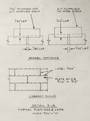
One thing I noticed you cut your plates at 22mm my drawing shows 5/8" (16mm)
Tony
There seem to be some differences between the 2 kits even though they are the same scale. The cross-section kit has been simplified in a number of ways. Like most Model Shipways kits that I have built, the plans offer lots of detail and it is up to the builder to determine how accurate and detailed to build the kit. After doing my plating, I can say that getting a consistent 1/64" overlap would be really difficult for me. Cutting 1/32" from the width is probably doable. The cross-section was designed (in the instructions) to use 1/4" wide plates with 1/32" overlap. As long as the plates are consistently overlapped it will likely look OK even if it is not completely scaled accurately.Hi Jeff
Great work with the copper plating, I've been putting off doing mine till now. I'm looking at ways to do mine there's lots of different ways to get the job done I just need to experiment a bit more.
One thing I noticed you cut your plates at 22mm my drawing shows 5/8" (16mm)
View attachment 424208
Tony
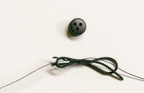
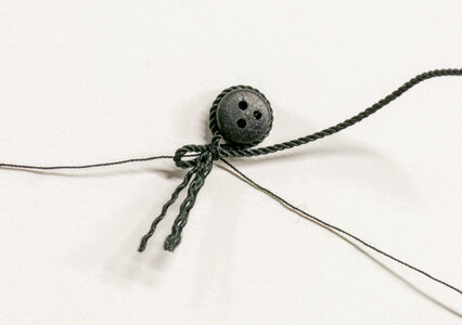
Channel deadeyes. The instructions show a method of mounting the lower deadeyes to the channels the use twisted wire to hold them in place. I chose to use rope instead. This required a different method for mounting them. I seized a loop of rope around the deadeye leaving a second loop to hook with the chainplate. The brass chain plates were blackened and bent prior to connecting them to the deadeye.
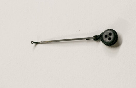
I used thin brass wire to pin the upper and lower chainplates to the hull. I small touch of black paint will be used to darken the pins after cutting them off flush with the chainplates.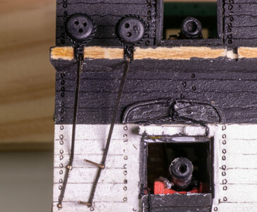
Note to future builders of this kit: MS supplies 10 sets of upper and lower chainplates with the kit. The rigging plans and pictures clearly show that there are 5 deadeyes per side so 10 seems correct. However, there is also a eyebolt required on the channel. This eyebolt is connected to the hull using the same upper and lower chainplates. Model Expo is very good about making good on missing or damaged items in their kits, so I placed a (cost free) order for more chainplates. I suggest that you do this early in the build so that you have them when you reach this point in the build. I will continue to the mast while I wait on the additional chainplates.


I used thin brass wire to pin the upper and lower chainplates to the hull. I small touch of black paint will be used to darken the pins after cutting them off flush with the chainplates.

Note to future builders of this kit: MS supplies 10 sets of upper and lower chainplates with the kit. The rigging plans and pictures clearly show that there are 5 deadeyes per side so 10 seems correct. However, there is also a eyebolt required on the channel. This eyebolt is connected to the hull using the same upper and lower chainplates. Model Expo is very good about making good on missing or damaged items in their kits, so I placed a (cost free) order for more chainplates. I suggest that you do this early in the build so that you have them when you reach this point in the build. I will continue to the mast while I wait on the additional chainplates.
Thanks Jeff I just wanted to make sure that I had the correct size. The copper tape not the easiest to work with, consistency is hard to achieve.There seem to be some differences between the 2 kits even though they are the same scale. The cross-section kit has been simplified in a number of ways. Like most Model Shipways kits that I have built, the plans offer lots of detail and it is up to the builder to determine how accurate and detailed to build the kit. After doing my plating, I can say that getting a consistent 1/64" overlap would be really difficult for me. Cutting 1/32" from the width is probably doable. The cross-section was designed (in the instructions) to use 1/4" wide plates with 1/32" overlap. As long as the plates are consistently overlapped it will likely look OK even if it is not completely scaled accurately.
I like the way your model is coming together and am toying with getting one for myself.
Tony


