USS Indianapolis CA-35 1/350 scale by Academy (Will @ Trilogy)

Looking at the bow and studying the photos I've found of navel records I"ve decided to use both Prontos and Eduard pe. Both kits bring different things to the build such as more detail with Prontos. Study the navel photo and compare it to the Eduard parts on the forward deck.
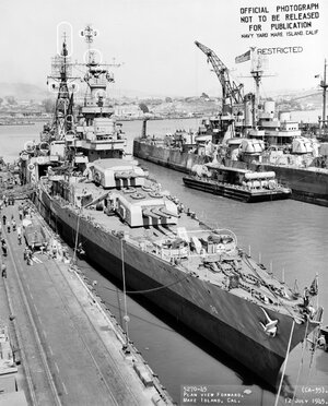
48EF1B12-B47D-49B2-BB89-A000071FF5FC.jpeg

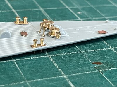
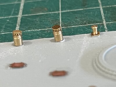
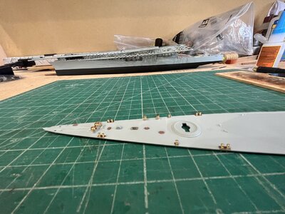
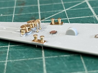
Looking closely you can see the ventilators which were left off the model. The large and small capstan bollard bits were just moulded bumps as seen in the above photo from yesterdays work. The wildcat control wheels were also omitted. All these parts are modeled with Pontos pe as seen in the following photos.
Photo of all pe from structure forward. (the white circles are modifications made in yard and detailed in the text.)
4C3E2A43-4C72-4F89-A077-808CD01AD6A9.jpeg
Port view of capstan to bollard bits and wildcat control wheels
D7764052-A686-47A6-96BC-D31CEBDAB7BC.jpeg

Same view from starboard
DDD58445-684A-44D1-BE32-CF9852D1D690.jpeg

Close up of ventilators on port side
BACBF491-ECF3-429E-BFAF-339CE911A22B.jpeg

That takes care of the forward deck and now is ready for assembly and painting. I"ve found the same differences in both pe kits so I"ll use both bringing the USS Indianapolis to a great display model.
 
Looking at the bow and studying the photos I've found of navel records I"ve decided to use both Prontos and Eduard pe. Both kits bring different things to the build such as more detail with Prontos. Study the navel photo and compare it to the Eduard parts on the forward deck.
View attachment 326041

Looking closely you can see the ventilators which were left off the model. The large and small capstan bollard bits were just moulded bumps as seen in the above photo from yesterdays work. The wildcat control wheels were also omitted. All these parts are modeled with Pontos pe as seen in the following photos.
Photo of all pe from structure forward. (the white circles are modifications made in yard and detailed in the text.)
View attachment 326044
Port view of capstan to bollard bits and wildcat control wheels
View attachment 326043

Same view from starboard
View attachment 326042

Close up of ventilators on port side
View attachment 326045

That takes care of the forward deck and now is ready for assembly and painting. I"ve found the same differences in both pe kits so I"ll use both bringing the USS Indianapolis to a great display model.
Hi Will,
I found the same thing with my current 1/200 USS Arizona build. I got both the Eduard and Mk1 PE upgrades because, as you said, each brings some different detail to the party.
Good luck with the build.
 
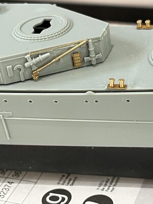
Well here we are in September and a month of slow progress on the Indianapolis. I've completed putting the Eduard and Pontos photo etch on the fore deck, aft deck, and fore structure. On the fore and aft decks the Eduard pe was for hatches and inner rings of the aft 40 mm bofor tubs.D844D51A-8C47-4881-973B-D9DADF9EA4A2.jpeg While the balance of the pe is from Pontos bonus parts. The Pontos parts are the deck vents ,fore and aft deck, capstan bollard bits.
On previous post I showed the ventilators on the fore deck while on the aft deck there are three sizes of ventilators with three gathered aft of the third 8" gun turret. Spent many hours working of the railings and ladders on the fore structure aft side that will be just forward of the airplane service deck. F8B75329-39D0-4758-908E-D4588EF0CCCF.jpegPontos also had the booms for securing launches.A4FFCCB9-7FB4-4561-9B66-BF41964629BC.jpeg

photo of fore deck and fore structure
4B2B6BC6-00AC-4C7D-917F-594825878B44.jpeg

Next will be the main gun turrets and then the fore and aft funnels.

To the next time sooner I hope.
 
I want to thank all for the likes of my work on the Indianapolis and hope you like the work ahead.

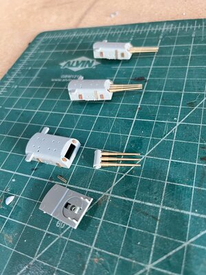
Doesn't seem that much is accomplished in the time spent but when the parts are done they look really good. I've found a wonderful YouTube build video of the Academy USS Indianapolis with Eduard photo etch by MaxAfterburner that I'm following the building steps. After what is already done the next thing is the main 8" gun turrets. It had doors to add and a ladder along with the barrel mounts. The Eduard kit uses the Academy parts and Pontos kit has very nice brass turned barrels which I used.
The finished main turrets
C6445CD0-F38E-48B6-AE02-D9EF0BA8FD5B.jpeg
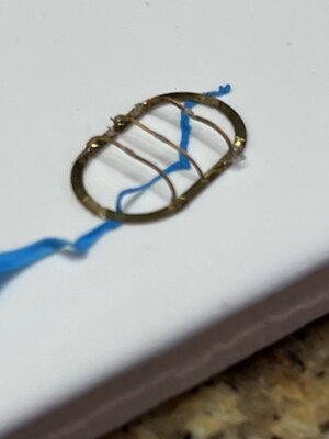
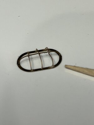
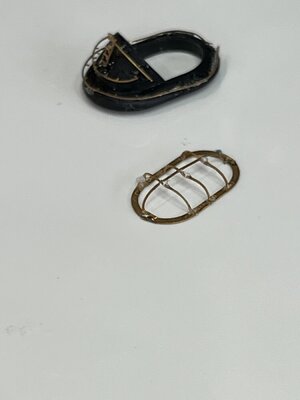
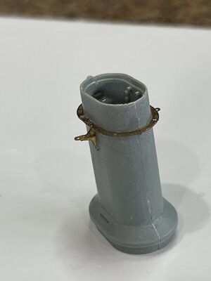
The forward funnel detail proved to be as difficult as the railings. The first thing is to remove the moulded shelf from the funnel and when complete add the rear steam vent pipe and once complete add the pe shelf in place of the moulded shelf. Under the shelf are 13 small triangle supports which gave me fits. Working with these tiny parts was very difficult with my left hand still somewhat restricted due to the shingles nerve inflammation. One tip I'd like to pass on is to cut an old pillowcase into squares and stretch and tape a square on the work surface. This resulted in a flat hard work surface the the small pe parts didn't bounce from after being dropped and landing who knows where. First part was the grill that fits in the top of the funnel. The parts are VERY thin and cutting them from the fret required a new blade after two or three cuts. To place the parts was fairly easy as the base piece had indentations where the cross wires attached. Using the sticky stuff to hold the base in place while attaching the cross wires.
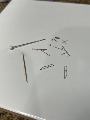
70F5373E-D718-4F5A-BFC9-83A1E88E3D37.jpeg
The last step is placing the longitudinal wire.
478EBE85-0BE1-4988-B595-39D2F83F1C4C.jpeg
Just a picture of the grill and top of funnel
A8AF5B5F-EA62-45C2-86B8-41FE89681367.jpeg

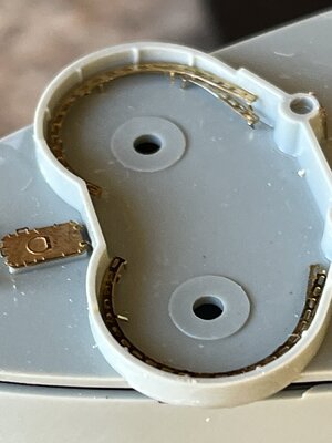
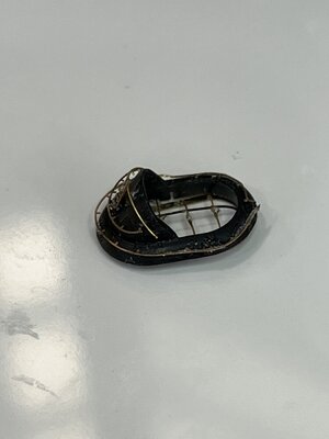
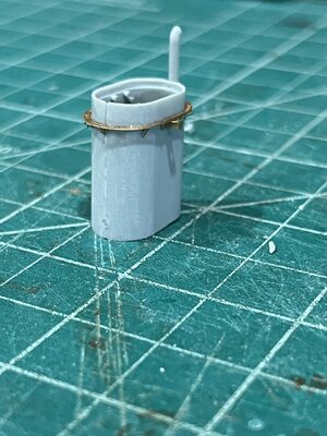
I forgot to take pictures of all the parts for the funnel top so I'll try to describe them the best I can. First is the ring around the base. It was on the fret it the size and shape ready to attach. Here is where I learned about new blades as you can see the ends are not against the base. The plan is to epoxy them in place holding with clips while the epoxy sets. Next is the lower hand hold which needs better attachment. Photos show all. It looked good til the photo. The the top hand hold and ladder. The grill inserted into the funnel top
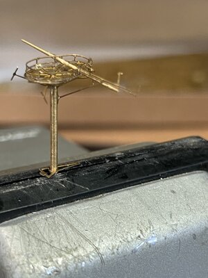
6D1C3604-90B6-490B-B350-02C9217DE24C.jpeg
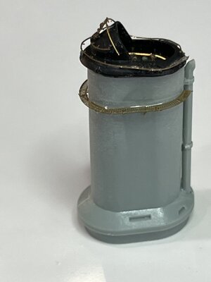
All the work with grill it really doesn't show itself very well but I know its there. This is the funnel and top dry fit and ready for primer and then glueing together.
The shelf on the funnel looks out of level but when the funnel is attached the angle makes the shelf parallel with the deck. You can barely see the little triangles supporting the shelf.
0D617121-26BD-4D75-93CC-5466517DFE67.jpeg
The next thing is the aft funnel which is just another exercise in frustration like the forward funnel. Maybe I'll start today. When preparing the moulded parts I'll take pictures of the process removing moulded features and attaching the pe parts.
 
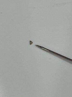
I forgot to post a couple of things about the forward funnel. First I complained about the size of the support gussets for the shelf so here is a picture. The pin is a standard push pin.
1F94EF48-5283-4965-AA61-82D062C86EAF.jpeg
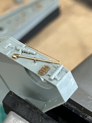
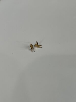
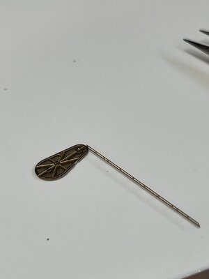
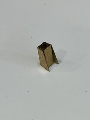
Now the same thing on the after funnel. The other thing I forgot to make was the whip antenna mounting bracket.
Bracket folded up

AEF39B22-D429-4FCF-B0E4-2878F1EA0ABE.jpeg
Brackets on sticky stuff and gussets ready for attaching.
1C49663E-B726-44F0-9CF4-1F788F89CCC5.jpeg
Gussets attached
001B9708-1328-4AED-86D3-1A6B4555A44C.jpeg
Finish brackets
02D7ABB1-8D0A-4034-88D7-155CF4C981D0.jpeg
Finished funnel
277C58BF-34B4-4E3C-89F5-E4F6DB84785D.jpeg
That's all for today Hope you enjoy
 
amazing all these small details - I am every time newly surprised how you guys can do these small details
 
As the builder on a 1:350 scale, I add to Uwe's post, those tiny details add to the model so much I can hardly explain, but working on those requires a good vision and perseverance as well as diligence. ;)
 
First things first and that is a BIG THANK You to Uwe and Jim for the nice comments it really helps my confidence. Being that this is the first plastic model in years and never using photo etch I look at my results and wonder if I could do better. I can see that I'm improving with my photo etch skills. So again guys thanks for the comments and likes.
Now I'm really proud of myself with the aft funnel work I've completed in four hours.
The sides of the funnel were not as flat as the forward funnel. I carefully filed them flat being sure not to disturb the alignment pins. The assembly of the funnel and steam exhaust pipe went smoothly and dried while eating lunch.
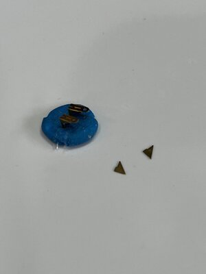
The pe shelf was easier to attach and went quickly and then came the dreaded triangle gussets. My method of working over a smooth cloth helped so when the tweezers dropped one it didn't bounce to "who knows where". With all 13 gussets placed and only lousing 2.
The mounting for the 36' whip antenna was different than the forward mount. This is a box with an open bottom. I folded up the box and attached to the shelf. I was amazed and getting it all done in 4 hours.
Picture of the aft funnel ready for the top.
7AA0436B-C57D-4A87-A435-CEDD817573C7.jpeg
 
I want to thank all for the likes of my work on the Indianapolis and hope you like the work ahead.

Doesn't seem that much is accomplished in the time spent but when the parts are done they look really good. I've found a wonderful YouTube build video of the Academy USS Indianapolis with Eduard photo etch by MaxAfterburner that I'm following the building steps. After what is already done the next thing is the main 8" gun turrets. It had doors to add and a ladder along with the barrel mounts. The Eduard kit uses the Academy parts and Pontos kit has very nice brass turned barrels which I used.
The finished main turrets
View attachment 329501
The forward funnel detail proved to be as difficult as the railings. The first thing is to remove the moulded shelf from the funnel and when complete add the rear steam vent pipe and once complete add the pe shelf in place of the moulded shelf. Under the shelf are 13 small triangle supports which gave me fits. Working with these tiny parts was very difficult with my left hand still somewhat restricted due to the shingles nerve inflammation. One tip I'd like to pass on is to cut an old pillowcase into squares and stretch and tape a square on the work surface. This resulted in a flat hard work surface the the small pe parts didn't bounce from after being dropped and landing who knows where. First part was the grill that fits in the top of the funnel. The parts are VERY thin and cutting them from the fret required a new blade after two or three cuts. To place the parts was fairly easy as the base piece had indentations where the cross wires attached. Using the sticky stuff to hold the base in place while attaching the cross wires.
View attachment 329518
The last step is placing the longitudinal wire.
View attachment 329517
Just a picture of the grill and top of funnel
View attachment 329520

I forgot to take pictures of all the parts for the funnel top so I'll try to describe them the best I can. First is the ring around the base. It was on the fret it the size and shape ready to attach. Here is where I learned about new blades as you can see the ends are not against the base. The plan is to epoxy them in place holding with clips while the epoxy sets. Next is the lower hand hold which needs better attachment. Photos show all. It looked good til the photo. The the top hand hold and ladder. The grill inserted into the funnel top
View attachment 329521
All the work with grill it really doesn't show itself very well but I know its there. This is the funnel and top dry fit and ready for primer and then glueing together.
The shelf on the funnel looks out of level but when the funnel is attached the angle makes the shelf parallel with the deck. You can barely see the little triangles supporting the shelf.
View attachment 329522
The next thing is the aft funnel which is just another exercise in frustration like the forward funnel. Maybe I'll start today. When preparing the moulded parts I'll take pictures of the process removing moulded features and attaching the pe parts.
Fine work Will.
 
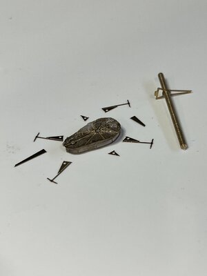
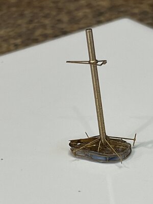
This morning I finished the aft funnel top as the forward top, so no excitement. The next step is the forward mast. Studying the Academy plans to understand the construction of the mast. Then comparing the Eduard and Pontos photo etch instructions I decided to use the Pontos photo etch. The Eduard pd modifies the original plastic by removing and then adding pe. The Pontos makes the mast out of turned brass and photo etch.
So off we go
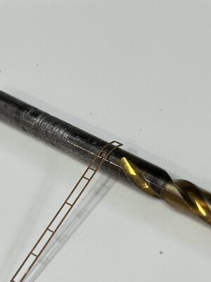
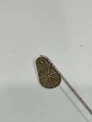
You need to take a platform of pe screen attach a layer of supports that are like the supports on the moulded piece. Not much to show. Then comes the fun there is a 2 row rail the goes around the perimeter of the platform.
My first idea was to attach the rail the smaller diameter and bend it around glueing as I went. We that didn't work as the glue adhesion wasn't sufficient to hold the rail. I went to lunch.
061C1835-9FD7-43AC-B211-887739F9EFA7.jpeg
In this picture you can see the support layer on top of the platform.
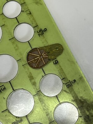
Thinking while eating I came up with an idea of how to get the radius of each end. Using a circle template identified the radius of each end.
5804A602-157D-44FF-AC90-B5E4D37BE03E.jpeg
With the diameter it was easy to use drill bit a mandrel to bend the rails radius.
0D35E25F-016D-41EE-8C53-0517C5405F93.jpeg
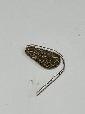
Once bent it was easier to attach the rail. One thing I found out the hard way was the rail sits on top of the platform not around its circumference.
F54633B8-5AEC-44A6-B525-445E3839B8CC.jpeg
using the same process for the large end forming the radius with a drill bit.
E3E9F913-D7A3-495A-AADE-2B8C85447792.jpeg
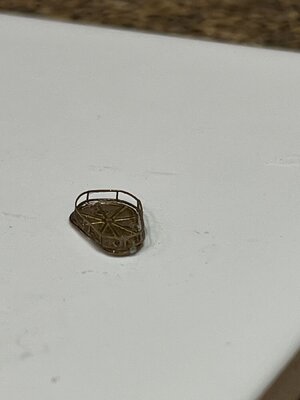
I had to smooth the top rail correcting the flat areas but when all done it came out nice. You can see a small space in the rail there will be a cross piece through this smaller opening and to my surprise the are in alignment.
ED18CB98-230B-44DE-9909-E139CBC13AA6.jpeg
The photos really magnify the flaws but the actual size the look great. No work tomorrow as we have a very busy day.
 
Got up early and had time to due some work on the Indianapolis. First thing was to cut all the parts from the fret.
4B9364A2-DA33-4F1E-9378-BA8D9BACE4DF.jpeg
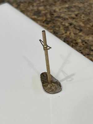
Next standing the mast shaft and attached the support angle. This angle will be for the rear mast shroud.
B22622E4-322A-4424-ABE7-B626264419A3.jpeg
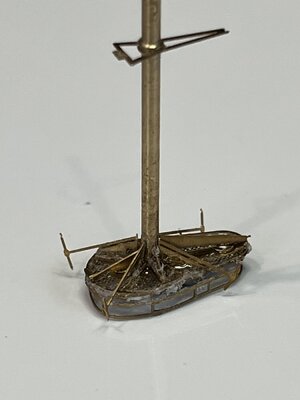
Next attach the antennas and angle supports and the finished top mast.
9F762499-8CF0-4281-9956-B366019C92DA.jpeg
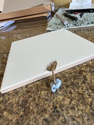
mast standing as will be mounted on ship and next the items on top of the topmast.
91435232-4D44-4169-83CA-61AA6E1977BF.jpeg
Until tomorrow

D2FA625C-017B-4B92-8C43-BA7654E8D462.jpeg
 
Note to self and anyone working with photo etch. When you have a joint between pe pieces that has a small attachment area (.i.e. a post attached perpendicular to a pe surface) CA glue will not offer sufficient joint strength. When I started attaching the cross yard the joint failed. I was very fortunate that all the support angles held and the topmast just rotated. What to do? Having read about similar problems they used 5 minute epoxy. I mixed up a batch and made fillets around the mast to topmast joint. Lets hope it holds.
With the yard mounted it is time to add the the equipment.
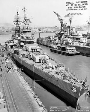
Here is a photo of the Indianapolis in 1945 while be refitted a the Mare Island navy base.
48EF1B12-B47D-49B2-BB89-A000071FF5FC.jpeg
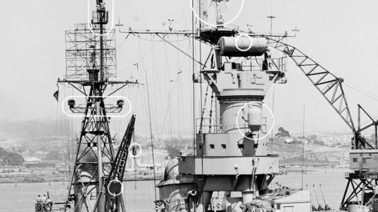
A closeup of the foremast taken from above photo
B8BA562B-5CBE-4F71-A921-0A996D2BEDF4_1_201_a.jpeg
The white circles are additions made in the yard during refit. On the cross yard notice all the gear attached on the top.
This photo shows all the Pontos pieces to make the cross yard.
D228C8F1-FED6-4278-9378-3F4165607A00.jpeg
and the top piece attached now need to place all the tiny pieces after the CA sets hard
D3B82339-F1DC-45A7-811F-4333F1E7ECF3.jpeg
Lunch time better the watching glue dry.
 
Thanks to all for the comments and likes. I check them each day and it helps me continue seeing all the likes.

Yes Paul I use magnification and if I need more a magnification glass to see tiny details and then go back to the headset. Thanks for asking I thing it was a tongue in cheek. HA HA HA
 
I'm new to the group, and Will, am really enjoying your build. I'm actually getting ready to start this ship with PE. Reading about your build is inspiring me to get started. I purchased the Pontos kit and now realize why I've heard so much griping about the instructions....holy crap!!! Will, your build looks fantastic and I'm looking forward to seeing more. Bob
 
Thank you Bob for the nice comments. My progress is very slow as I'm still recovering from a Shingles attack that has made my left thumb and forefinger paralyzed. The nerves are regenerating and movement and feeling are returning.
Enough about me lets talk modeling. Here are some things I've found.
Study the plans
Search YouTube for 'Build the USS Indianapolis 1/350 Academy MAX_Afterbuner' this is a great step by step build
Follow the Academy flow adding the PE as you go
Cut PE with sharp blade on a hard surface.
Blades make 3 cuts without damaging the PE
Good luck
 
Thanks Will, I appreciate your advice. I've used pe quite a bit with aircraft models so hopefully I won't have too many issues in that regard. Interpreting some of the instructions with the Pontos pe is going to be a challenge. I started working on the hull and secondary armament, so far so good.

Hang in there with your recovery. I went through that a few years ago and it does get better. Take care. Bob
 
Thanks Bob. Yesterday I made some progress on the forward fire control director.
Couple pictures of the process
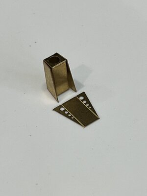
The base for the director made from one piece with three folds. Side, back, side as show standing
EB0BECFB-08D5-412B-B56D-D80C01165086.jpeg

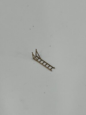
Two ladders folded
3EFC7016-3B33-4FE0-BAB8-4FB1B4DB0197.jpeg
Looking at pictures of the ship showing a ladder attached to the post that I assume would gain entry to the gun director. On the forward gun director this ladder would not be required due to the close proximity of the bridge.
With the base finished the cross support can be added
7BA29B0C-152E-4981-A25E-B1B289EF7D74.jpeg
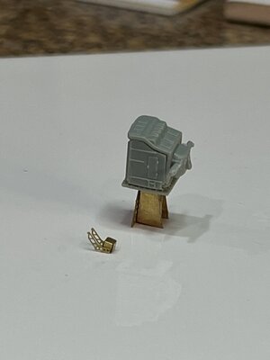
Now the director house is added to the base
C2D831F0-EA02-4AC5-A5CC-C4F6FDC7D3DA.jpeg
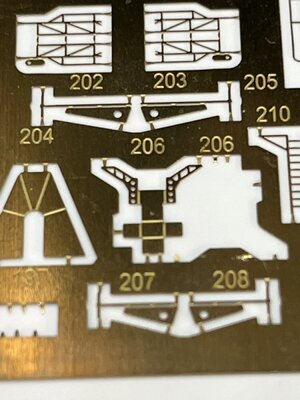
The antenna support can be seen at the bottom of the gun director. The little antenna support can be seen on the sheet for your reference. (item 206)
E216DD30-179D-4F2E-8FAB-89A9E0874D9D.jpeg
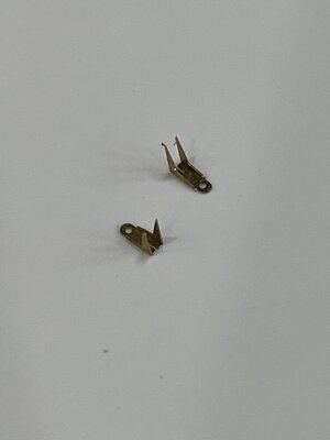
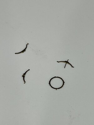
The antenna is made from below pieces. The two eyebrow shaped pieces are to be bent to 60 degrees forming a V and the cross shaped piece is the center. When all assembled it form the dish shaped antenna.
B899A5B5-E529-4B14-A5C6-D08A6B08F457.jpeg
You'll notice the amount of filling to be done before attachment.

So long for now
 
Thanks for sharing Will. You're doing a fantastic job with all of the small PE parts and the model in general. These parts add so much to the overall look of a build in this scale, truly impressive. I look forward to seeing more. Take care
 
The next step is to prime the bridge structure components and that brings up a question that i'd like some help with, the 1945 ship paint color measure calls for all horizontal decks to be deck blue (US10) and superstructure to be haze gray (US08). My question is: Should I paint the deck blue and then tape it over to paint the haze gray or just paint everything haze gray? I plan to paint all the component prior to assembly so the taping would be on each of the individual pieces.

Help or suggestions
 
Back
Top