-

Win a Free Custom Engraved Brass Coin!!!
As a way to introduce our brass coins to the community, we will raffle off a free coin during the month of August. Follow link ABOVE for instructions for entering.
-

PRE-ORDER SHIPS IN SCALE TODAY!
The beloved Ships in Scale Magazine is back and charting a new course for 2026!
Discover new skills, new techniques, and new inspirations in every issue.
NOTE THAT OUR FIRST ISSUE WILL BE JAN/FEB 2026
You are using an out of date browser. It may not display this or other websites correctly.
You should upgrade or use an alternative browser.
You should upgrade or use an alternative browser.
USS Oliver Hazard Perry FFG 7 by Academy with Pontos 1:350
- Thread starter Will @ Trilogy
- Start date
- Watchers 21
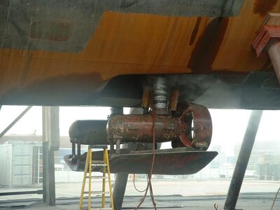
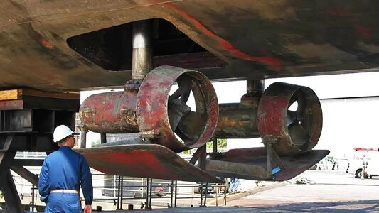
Yes Igor. The two shown I believe are the side thrusters that deploy when needed. The book by Glenn Hoover is a step by step instruction of how he built the model.
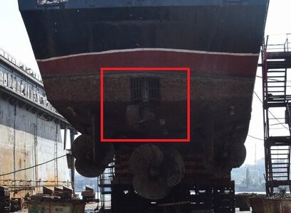
This device is designed to maneuver the ship at low speeds in ports when the main propeller cannot provide maneuverability at low speeds. During the attack on USS Stark (FFG-31), when the stationary frigate was hit by two anti-ship missiles, this device could help turn the ship in place so that the missiles were in the Vulcan Phalanx sector of fire. But that didn't happen...not side thrusters as would have been installed into the sides of the bow for sideways motion. look at Sheet 12 Hold as they are apu 1 & 2 for use if the main prop stops working for whatever reason.
You are wrong. They really rotate around their axis. But there are clear recommendations for their use from NAVSEAi don't think the apu's can rotate as distance between the 2 is not great enough that they don't interfere with each other. i think they can only go forward & reverse as they are emergency propulsion units.
Handling the FFG-7
- Joined
- Aug 14, 2018
- Messages
- 825
- Points
- 403

I agree JJ..You are wrong. They really rotate around their axis. But there are clear recommendations for their use from NAVSEA
Handling the FFG-7
Great comments on the side thrusters, I learned a lot. Thank you navsea information and yes this is the book I wrote about.
- Joined
- Jul 2, 2022
- Messages
- 137
- Points
- 88

Nice to have. Very cool.
The PE work is a lot of work! But looks fantastic. I hope the epoxy and JB Weld is working. A few years ago I half tried to build a "PE Welder." It's sort of a "flash" soldering iron: high juice for super quick solder melting. You can buy them for the cost of a Lamborghini, so I thought I'd make one. But the parts add up to the cost of just buying one...
I don't really do very much PE work, but I thought it would be handy and cool.
Keep us updated with your progress.
A "PE Welder" hum!! On another project I'm making small fittings using brass rod and copper wire bonding the parts with silver solder. A problem was some of the parts are around wooden blocks and too much heat. I invested in a resistance soldering system which did not burn the wooden blocks and might try this on pe parts. I don't think this would work on the plastic model but many of the pe parts have to be assembled i.e. the radar towers. Something to try.
Thanks Rokket it was a very challenging and fun model and makes a great display. Most people who look at models don't notice the detail on board but everyone who has seen the Perry always comments on the masts.
- Joined
- Jul 2, 2022
- Messages
- 137
- Points
- 88

OK, it's a resistance soldering system. Uses a foot pedal. Sort of like spot welding. Seemed cool (or really hot!). If I ever do a heap of PE, I'll look at investing in one. My super-cheap scheme to build had way too many holes! It might be bad for plastic, but anything that could be constructed separate might be good.A "PE Welder" hum!! On another project I'm making small fittings using brass rod and copper wire bonding the parts with silver solder. A problem was some of the parts are around wooden blocks and too much heat. I invested in a resistance soldering system which did not burn the wooden blocks and might try this on pe parts. I don't think this would work on the plastic model but many of the pe parts have to be assembled i.e. the radar towers. Something to try.
Nowhere can I find the second sheet of this drawing, with a description of all the markings
Indeed, I meant the first sheet. On this sheet of the drawing there should be a specification, namely the dimensions and purpose of all external holes, which are indicated on the drawing only by numbers.don't you mean the 1st sheet as that is the 2nd sheet as stated on bottom right corner "2 of 2"? i do not have the 1st sheet. what markings are you looking for?


