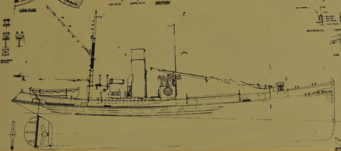
Working Steam powered wooden Drifter trawler, Formidable LT100, 1:24th scale

Part 8.

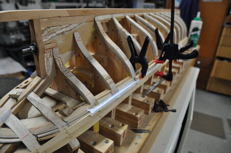
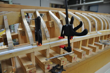
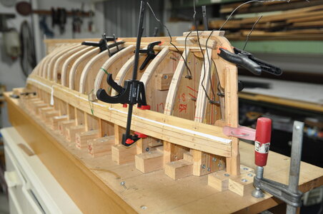
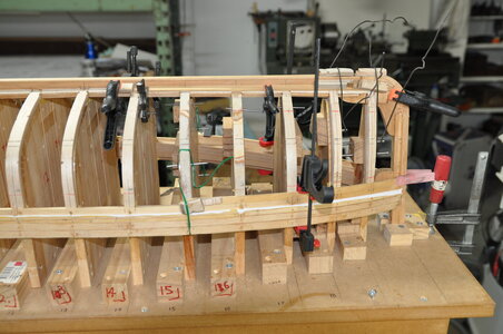
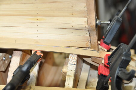
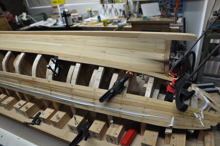
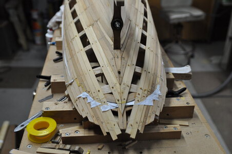
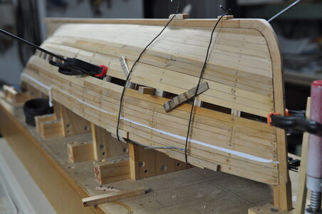
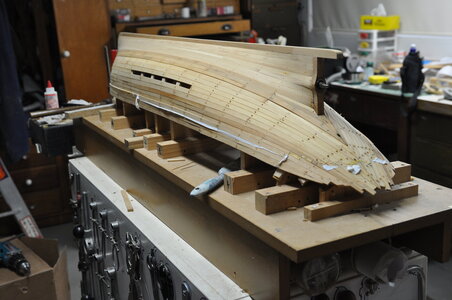
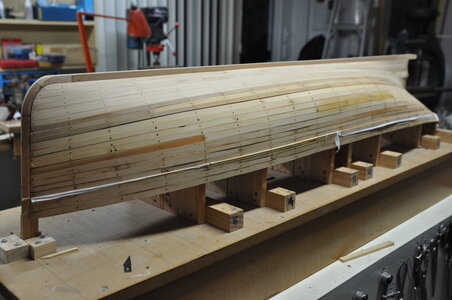
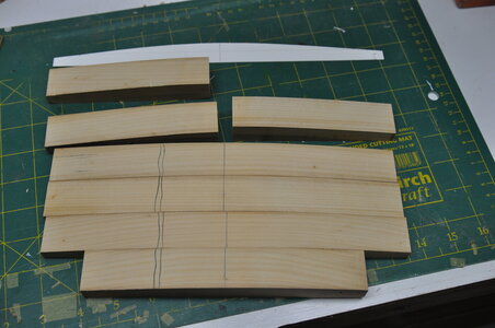
Planks are made of Huon pine, rubbing strakes being thicker than the normal planks, all to a scale thickness. This wood has a unique aroma, I my opinion quite a pleasant smell it seems to permeate the workshop when sawing/sanding.

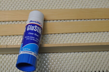
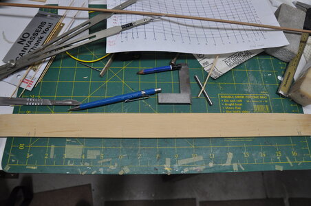
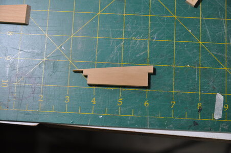
Planks were made in pairs being temporarily glued together using a Glue stick. First the planking material would have a straight and square face planned on using a jack plane, then the width marks would be marked at each frame along with the overall length.

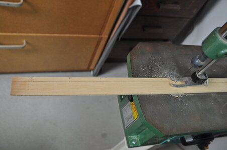
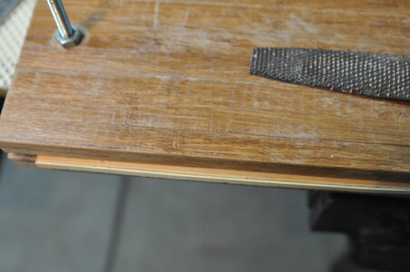
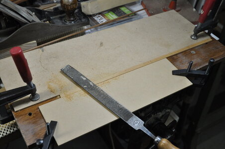
Next rough cut on a scroll saw finishing to the line with rasp and sand paper making sure the edge remained square, in the end it became a process and I got faster and better as I progressed.

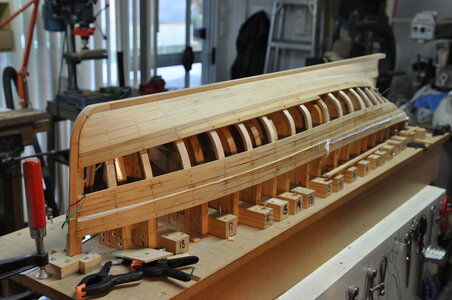
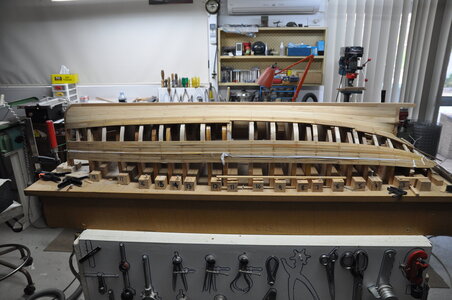
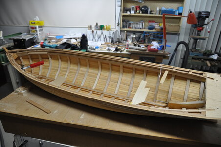
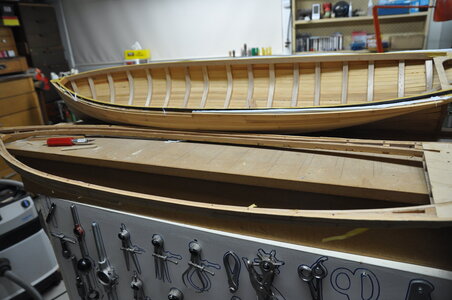
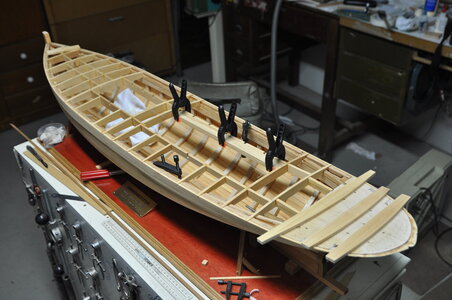
I would go out to my workshop on a week night after dinner for an hour or so and from memory I could make steam then fix two pair of planks in a week. I planked from the keel and deck edge meeting in the middle

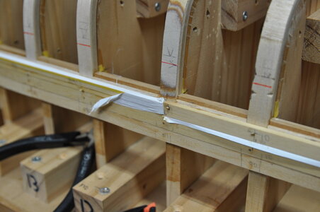
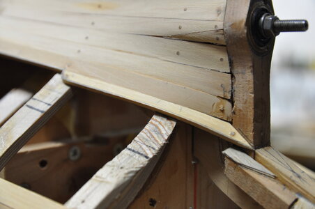
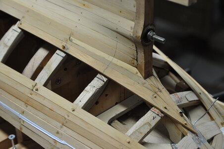
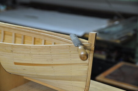
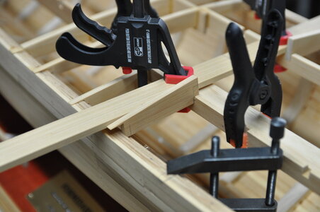
Planks were made and attached in pairs, when needed they were steamed, waiting a few days after steaming then glued, drilled and having bamboo tree nails knocked in. The tree nails are a lot bigger than scale mainly to improve strength and seeing that the hull will be painted you probably wont see them.

DSC_1075.JPGDSC_1077.JPGDSC_1079.JPGDSC_1080.JPGDSC_1081.JPGDSC_0576.JPGDSC_0577.JPGDSC_0580.JPGDSC_0587.JPGDSC_0588.JPG

Cheers,
Stephen.
 
Part 7.

Returning to completing work on the removable section once that was done I could start on planking.

After adding some keel doublers, fairing the frame’s checking progress with a fairing batten until I was happy that my planking would sit flat on the frame’s and into the rabbet.

From Tree to Sea tells me that LT 100 had 22 strakes on each side of the hull. Following Harold Underhill’s instructions to work out the run of planks I ran 3 temporary battens starting around mid ships on the turn of the bulge on each side of the hull to divide it into 4 areas, the other two battens halving the area left.

The objective is to get these battens to sit flat on the frame doing this without bending up or down pull them around the hull so they sit nicely, a fair bit of fiddling around is required, adjusting looking from different angles until you are happy with there appearance, then walk away for a while come back and check again!

I ended up changing the run of these battens several times, ending up using a red pencil to mark the final run because there were too many pencil marks! Once these 4 areas had been marked out accurate measurements were taken along the circumference of the frames.

Two of the areas would have 6 strakes each, with the other two areas having 5 strakes. Proportional dividers were used to divide these areas to give the plank width at each frame.

Before going any farther a “butt diagram” was worked out to find where the plank ends would fall, as it turned out this was a very handy thing to have.

I made a plank holding clamp that made it easier for me to hold and trim down planks.

I also made a steaming apparatus, an old electric kettle being the steam source a length of galvanised down pipe with a “T” put into it at one end and a piece of mesh bent to form a shelf for planks to lay on while being steamed.

I intended to plank this model in a fashion similar to the real boat, for the most part I think I have achieved this.View attachment 183121View attachment 183122View attachment 183123View attachment 183124View attachment 183125View attachment 183127View attachment 183128View attachment 183129View attachment 183130

Chers,
Stephen.
Your care for precision and patience are showing and will pay off in the final results. Well done! PT-2
 
Part 7.

Returning to completing work on the removable section once that was done I could start on planking.

After adding some keel doublers, fairing the frame’s checking progress with a fairing batten until I was happy that my planking would sit flat on the frame’s and into the rabbet.

From Tree to Sea tells me that LT 100 had 22 strakes on each side of the hull. Following Harold Underhill’s instructions to work out the run of planks I ran 3 temporary battens starting around mid ships on the turn of the bulge on each side of the hull to divide it into 4 areas, the other two battens halving the area left.

The objective is to get these battens to sit flat on the frame doing this without bending up or down pull them around the hull so they sit nicely, a fair bit of fiddling around is required, adjusting looking from different angles until you are happy with there appearance, then walk away for a while come back and check again!

I ended up changing the run of these battens several times, ending up using a red pencil to mark the final run because there were too many pencil marks! Once these 4 areas had been marked out accurate measurements were taken along the circumference of the frames.

Two of the areas would have 6 strakes each, with the other two areas having 5 strakes. Proportional dividers were used to divide these areas to give the plank width at each frame.

Before going any farther a “butt diagram” was worked out to find where the plank ends would fall, as it turned out this was a very handy thing to have.

I made a plank holding clamp that made it easier for me to hold and trim down planks.

I also made a steaming apparatus, an old electric kettle being the steam source a length of galvanised down pipe with a “T” put into it at one end and a piece of mesh bent to form a shelf for planks to lay on while being steamed.

I intended to plank this model in a fashion similar to the real boat, for the most part I think I have achieved this.View attachment 183121View attachment 183122View attachment 183123View attachment 183124View attachment 183125View attachment 183127View attachment 183128View attachment 183129View attachment 183130

Chers,
Stephen.
Dear Stephen
This is a very creative invention, well done
 
Part 9.

Some more planking photos….. I hope you enjoy them.

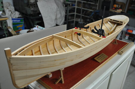
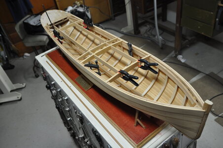
When it came to fitting the rubbing and bilge strakes I tapered the respective planks which are thicker than the rest of the planking material, before fitting them I felt that I would make a mess of it if I tried tapering them once fitted.

Planking around the stern I found to be the trickiest especially around the prop shaft. In one of those regrettable moments of “she will be right” and take the easy rout I will just make up a couple of wedge shaped planks to fill a hole, instead of making a proper “stealer”. Later on I did go to the trouble of making a better “stealer” this can be seen in a couple of the photos.

When I got to the last plank ( quite a mile stone event ) I was very happy and relived that there were no large adjustments to be made. I doubt anyone would be able to find it without referring to a photo first.

Somewhere in the 2 or 3 years that planking took me to do, I showed the model at a few shows.

One show in particular at Queenscliff maritime museum in Victoria Australia. I ran into a guy Les Lauder he had built 2 engines to the same design as I did, he told me that one of them ran beautifully without problems while the other had similar problems to mine.

He told me that he had fixed this problem by using a floating frame to push the cylinders onto the valve face. He very kindly sent me some photos of his modified engine.

This mention of steam engine problems and other steam related issues will be covered in the future.

Updates will slow considerably now that the pre-written stuff is depleted, also I work full time. There is still quite a bit to catch up to the latest work.

DSC_1153.JPGDSC_1259.JPGDSC_1260.JPGDSC_1266.JPGDSC_1268.JPGDSC_1278.JPGDSC_1279.JPGDSC_1284.JPGDSC_1291.JPGDSC_1308.JPGDSC_1312.JPG

Cheers,
Stephen.
 
WOW
Just "found" your new building log
This is a great project and a very good and informative building log - I am looking forward to see much more of your work on this model
BTW: Your "steamer" is great - wonderful idea
BTW2: Can you show us a photo or sketch / drawing, so we see how the ship will look like?
I found a kit including a GFK-hull, which is in the meantime available
 
Last edited:
Hi Uwe,

This is a small section of a brief introduction that I use when displaying my model.

1601963363415.png


Formidable, LT 100, a wooden steam drifter trawler built in 1917 by Chambers Ltd at their no.3 yard, Oulton Broad, Lowestoft, Suffolk, England.

Approximately 88 feet in length, 19 feet beam with a depth of 9 feet 9 inches, 40 tons net, carrying capacity of 52 tons, fitted with a two-fired Riley boiler, and a Crabtree compound steam engine of 33hp she could run economically at a speed of 9 knots.

The model is being built to 1/24th scale and is scratch built from plans drawn by John Pottinger; she is 1.2m long, powered by a steam engine and radio controlled.

Cheers,
Stephen.
 
Part 10.

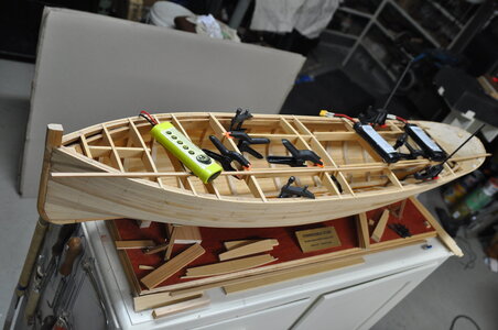
After planking had been finished came removal from the building board then removing all the former's from inside the hull, and at last time to separate the upper and lower parts of the hull (that’s if I hadn’t accidentally glued them together).

I used small wedges to force the parts apart and to my relief after some initial reluctance to move with a pop the two parts started to separate.

I continued carefully prising the two parts apart taking my time to ensure I didn’t damage anything.

I would have to say that I was very happy with my effort so far, I quite like the lines on this hull.

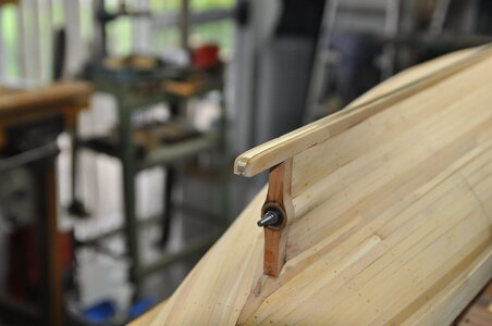
I used a rasp and sandpaper on a stick to carefully trim down to the sheer line.

I put the hull back on the building board temporally using a couple of former's to hold it in position this was so I could make and fit the “sand band”.

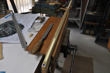
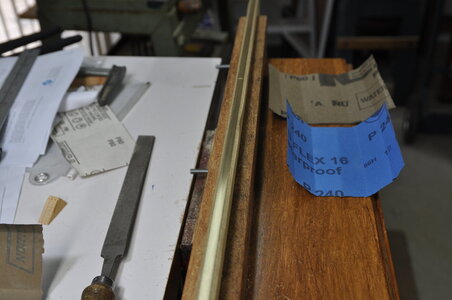
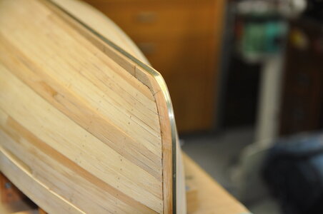
The sand band on the real thing was a “D” section made of mild steel. After looking around I couldn’t find any brass “D” section the right size so I decided to make my own from brass strip shaped into a “D” section.

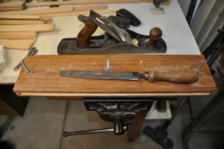
After contemplating how I could do this I came up with attaching the strip to a flat board with double sided tape.

Then using a file and sand paper producing the required shape.

After bending to shape the sand band was glued with Titebond 3 and pinned using brass pins.

I did some experiments gluing brass to wood using Titebond 3 with great results it adhered very well, I scratched up the brass before gluing with coarse sand paper, then chemically cleaned using thinner or isopropyl alcohol to remove any contaminates.

DSC_1328.JPGDSC_1333.JPGDSC_1335.JPGDSC_1339.JPGDSC_1340.JPGDSC_1341.JPGDSC_1346.JPGDSC_1394.JPGDSC_1397.JPGDSC_1400.JPGDSC_1407.JPGDSC_1415.JPGDSC_1435.JPGDSC_1420.JPG

Cheers,
Stephen.
 
Beautiful work indeed Stephen. I really like your way to use the laminated bulkheads! I am going to steal this idea for my next build.
And your way to separate hull in two is a splendid one, giving full access to the lower part of hull for installing engine & other components. Another great idea for copying.
I will follow your build with great interest into the very end, we will see what other exceptional ideas there will still be uncovered.
 
Hi Moxis,
Thanks for your comments, I appreciate them. They say, imitation is the greatest form of flattery.
If you do go down the laminated frame path I would recommend using a good quality thin ply wood.
I would not recommend the removable section if going for the bent frame method the amount of work is ridiculous.
For me the removable section was an after thought, it would have been better to have used cut frame I think. Then you could plan the removable section from the start.
I hope you enjoy the build and I don't disappoint you in future posts.
Cheers,
Stephen.
 
Stephen,
Have just found this thread! Beautiful work!
The steam trawlers have always had a great attraction for me, and I always intended to build one, but sadly I am now a SABLE and will probably never get round to it. Your construction techniques are excellent, and remind me so much of my build of 'Natterer' - except I took 33 years on her, rather than 20!
I agree that Ted Frost's book is superb.

Regards

Ted
 
Part 10.

After planking had been finished came removal from the building board then removing all the former's from inside the hull, and at last time to separate the upper and lower parts of the hull (that’s if I hadn’t accidentally glued them together).

I used small wedges to force the parts apart and to my relief after some initial reluctance to move with a pop the two parts started to separate.

I continued carefully prising the two parts apart taking my time to ensure I didn’t damage anything.

I would have to say that I was very happy with my effort so far, I quite like the lines on this hull.

I used a rasp and sandpaper on a stick to carefully trim down to the sheer line.

I put the hull back on the building board temporally using a couple of former's to hold it in position this was so I could make and fit the “sand band”.

The sand band on the real thing was a “D” section made of mild steel. After looking around I couldn’t find any brass “D” section the right size so I decided to make my own from brass strip shaped into a “D” section.

After contemplating how I could do this I came up with attaching the strip to a flat board with double sided tape.

Then using a file and sand paper producing the required shape.

After bending to shape the sand band was glued with Titebond 3 and pinned using brass pins.

I did some experiments gluing brass to wood using Titebond 3 with great results it adhered very well, I scratched up the brass before gluing with coarse sand paper, then chemically cleaned using thinner or isopropyl alcohol to remove any contaminates.

View attachment 184635View attachment 184636View attachment 184637View attachment 184638View attachment 184639View attachment 184640View attachment 184641View attachment 184642View attachment 184643View attachment 184644View attachment 184645View attachment 184646View attachment 184647View attachment 184648

Cheers,
Stephen.
Dear Stephen
as always, you are doing excellent job, it's looks beautiful
 
G'day Stephen, what a beautiful model you are building, just when I had decided not to build anymore 20th century type ships, you go and post this fantastic build, would you believe that I had got rid of any plans for them except this one, I had tossed and turned whether to give the plan away but in the end I kept it.
I will have to go back and read all through your log, I expect it will be a very enjoyable read,

best regards John.
 
Last edited:
Stephen,
Have just found this thread! Beautiful work!
The steam trawlers have always had a great attraction for me, and I always intended to build one, but sadly I am now a SABLE and will probably never get round to it. Your construction techniques are excellent, and remind me so much of my build of 'Natterer' - except I took 33 years on her, rather than 20!
I agree that Ted Frost's book is superb.

Regards

Ted
Hi Ted,
Thank you very much, I was hoping that you might find my build.
I am in awe of your work and there are some parallels with your magnificent "Natterer", though I am hopeful that completion of my model will be less than 33 years.
I don't know where I would be without Ted Frosts book it is indispensable.
Cheers,
Stephen.
 
Back
Top