Working Steam powered wooden Drifter trawler, Formidable LT100, 1:24th scale

G'day Stephen, what a beautiful model you are building, just when I had decided not to build anymore 20th century type ships, you go and post this fantastic build, would you believe that I had got rid of any plans for them except this one, I had tossed and turned whether to give the plan away but in the end I kept it.
I will have to back and read all through your log, I expect it will be a very enjoyable read,

best regards John.
Hi John,
Thanks.
Sorry for upsetting the apple cart for you.
Let me know what you think of the log. I am always happy to hear constructive comments.
Cheers,
Stephen.
 
Part 11.

I got a bit excited and posted more photos than than were required in the last post, mainly referring to deck beams.

So here is the description.

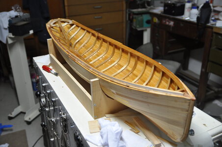
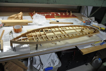
I made up a cardboard template for the deck beam camber and using some Kari pine made up a batch of deck beams.

Using my newly acquired Byrnes Table saw I cut and fitted the beams placing them in reference to major deck openings.

The width of deck beams is close to scale, though the number is not correct. Depth of these beams is not to scale due to a desire to stiffen up the removable structure.

Then my focus turned to how I was going to attach the removable section and how I was going to secure it.

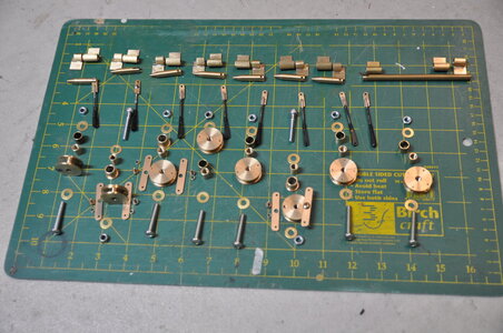
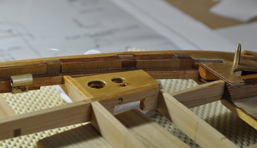
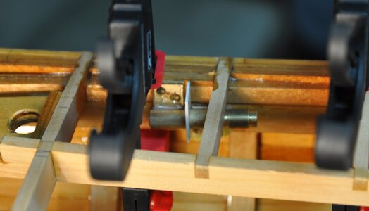
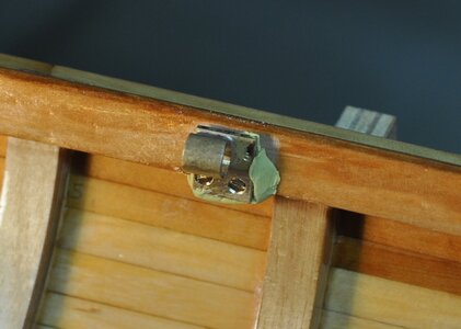
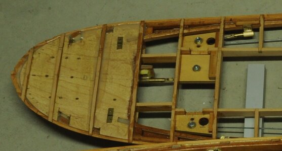
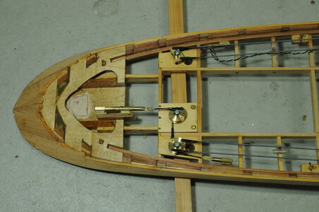
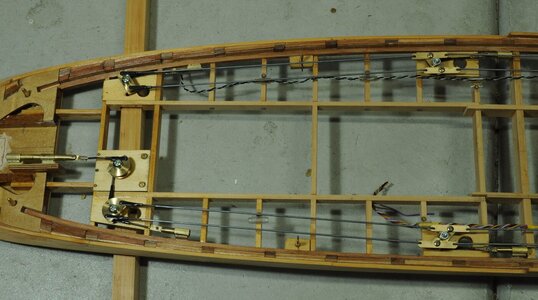
What I came up with was a system of cams and push rods, having 4 sliding pins on each side for a total of 8 pins.

To achieve this required a lot of components, once again taking a lot longer than first thought. The main motivation for this design was my distaste for removing 6 to 8 screws each time I wanted to remove the top section, I wanted to just turn 2 screws and then be able to remove the top section.

You may ask why so many pins, in my opinion the top section is not a stable structure by it self, if it is not held in place properly it will move out of shape over time, hence all the pins to hold it in place.

When I was making the components, in the back of my head was if any of this fails removal will be difficult in the extreme. With this in mind all rotating elements had bushings. Pivots for linkages on the pins were “riveted” using a watch makers staking set to ensure no pivot falls out.

Locating pins were also fitted to ensure alignment when putting the top on, hopefully eliminating possible damage to planking when replacing the top section.


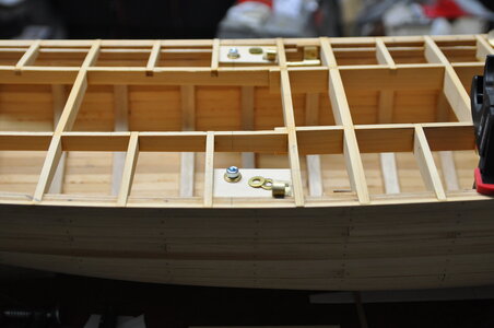
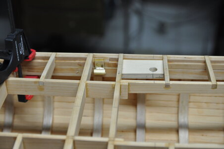
I then installed the pin guides and sockets, not relying on an adhesive alone I used small brass wood screws to mechanically fix the components. I started with the pin guides mounting then to the removable section. Then aligning the sockets using a tight fitting pin together with a spacer between the two I initially glued the sockets in position with Milliput once set I screwed them in just to be sure.

DSC_1437.JPGDSC_1463.JPGDSC_1464.JPGDSC_1479.JPG
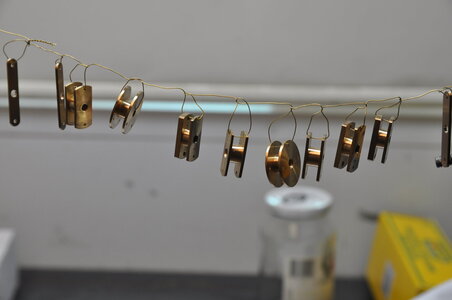
All components were given a coat of clear lacquer before fitting.

DSC_1488.JPG
The inside was given a couple of coats of epoxy resin. I am happy to say that very little epoxy ran through to the other side as there were not many gaps in the planking.

DSC_1489.JPGDSC_1493 (2).JPGDSC_1496 (2).JPGDSC_1497 (2).JPGDSC_0637 cropped.jpgDSC_0953.JPGDSC_0954 (2).JPG

Thanks for looking in.

Cheers,
Stephen.
 
G'day Steve, well what can I say, your model is absolutely impeccable, and the description and photo's are the same, I have a 32" monitor on my PC set up and your pics are absolutely stunning, you got me worried now.

I was sitting having a conversation with myself, it happens quite often, I was telling myself that I couldn't find the plans for the Formidable and that I must have given them away with the other plans, anyway a little voice answers back and says dont worry I have ordered a new set from Cornwall Model boats, cor blimey I say's now I'm gonna be in the deep you know what with the missus, and the little voice comes back again and says, its gonna be very deep because I also bought the book from Tree to Sea as well, so while I'm waiting for them to arrive Iv'e gotta couple of trips booked for the psychiatrist for the both of us.

If I build it, thats a big if after reading through your build log, I will probably just build as a decorative model, anyway thanks for the inspiration, and i look forward to the rest of your build,

best regards john,
Thanks John,
Why are you worried? Sorry I can be a bit thick sometimes.

What you too, conversing with yourself... I hope the Admiral is not too upset, and From Tree to Sea is indispensable in my opinion, all those little nuggets of information.

I hope I don't put you off building your own drifter.
Cheers,
Stephen.

Its just that you have made such a superb job of yours, I'm waiting for the plansto see if I can build her with just frames no formers, if it comes to it I can just make the frames a little bit wider than they should be, will see how it goes,

best regards John,
 
Part 12.


I decided to leave planking the deck and making the bulwarks until later, my main reason is ease of positioning equipment when I have clear sight through the deck beams, this turned out to be a really good idea.

Back to the steam engine. The following steam engine issues happened over a number of years, not necessarily in order with building of the hull as presented in these articles.

To recap from part 2; first run showed that it took a very very long time to raise steam and once it did raise steam the engine didn’t run for long before the pressure dropped.

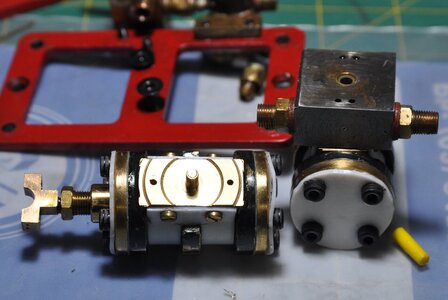
I only ran the engine three times before I had large leaks mainly between the cylinder port and distribution block faces, the leaks being so big the engine wouldn’t run properly!

I wasn’t sure why I was having these problems, I thought I had made the engine as accurately as I could. I pulled the engine apart and found that the distribution block now had slop in the bearing for the cylinder pivot.

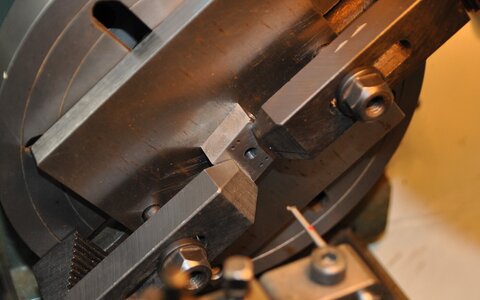
I was puzzled that this should occur with so little running time, at that point I thought either the pivot pin or bearing hole wasn’t square to there respective face. I couldn’t understand how this could happen, but I couldn’t think of any other reasons either. So I set up the cylinder in a 4 jaw independent chuck, not easy to do, then took a skim off the face, then repeat again for the other cylinder.

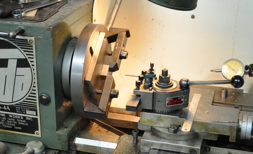
Next I setup the distribution block on a face plate and bored the bearing hole out this would ensure an absolutely perpendicular hole, then made a bronze bush and pushed it in.

I reassembled the engine with high hopes only to have a similar result after a few runs I had huge leaks again, I started to think this steam thing might not be for me.

Then while I was exhibiting my partly built drifter at a model boat show at the Queenscliff Maritime Museum in Queenscliff a bay side township in Victoria, Australia, I met a guy who had built 2 of the same engines that I had. While talking he asked me how my engine was going and I told him not so good. He told me that one of his engines ran beautifully while the other was terrible like mine.

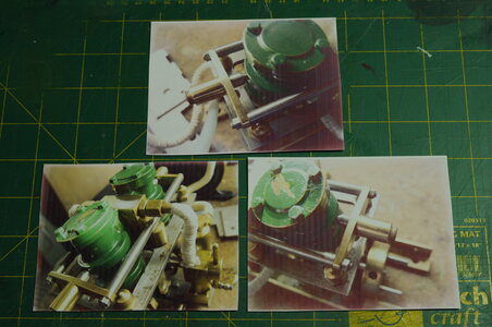
He then proceeded to tell me how he over came the problem also saying he would send me some photos of his modification, photos eventually arrived of his floating cylinder retaining device ( I don’t really know what to call it ).

DSC_1705.JPG

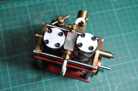
I proceeded to copy his modification along with another modification on the cylinder faces to under cut between the pivot pin and steam port, reducing surface area.

DSC_0044 (2).JPG

Then for the second time I set the distribution block on a face plate and bored the pivot hole out this time for DU Glacier bushes.

DSC_0123 (2).JPGDSC_0124 (2).JPG


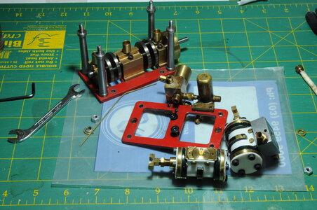
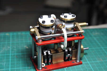
I re-assembled the engine then put it aside, hoping it would run as intended.

DSC_0046.JPGDSC_1709.JPGDSC_1708.JPG

Thanks for having a look.

Cheers,
Stephen.
 
G'day Stephen. my book has arrived but I'm still waiting for the plans, had a quick look through the book and there is a great deal of useful info in it, a joy to read on its own, I'm looking forward to more of your build,

best regards john,

947.jpg


.
 
Part 12.


I decided to leave planking the deck and making the bulwarks until later, my main reason is ease of positioning equipment when I have clear sight through the deck beams, this turned out to be a really good idea.

Back to the steam engine. The following steam engine issues happened over a number of years, not necessarily in order with building of the hull as presented in these articles.

To recap from part 2; first run showed that it took a very very long time to raise steam and once it did raise steam the engine didn’t run for long before the pressure dropped.

I only ran the engine three times before I had large leaks mainly between the cylinder port and distribution block faces, the leaks being so big the engine wouldn’t run properly!

I wasn’t sure why I was having these problems, I thought I had made the engine as accurately as I could. I pulled the engine apart and found that the distribution block now had slop in the bearing for the cylinder pivot.

I was puzzled that this should occur with so little running time, at that point I thought either the pivot pin or bearing hole wasn’t square to there respective face. I couldn’t understand how this could happen, but I couldn’t think of any other reasons either. So I set up the cylinder in a 4 jaw independent chuck, not easy to do, then took a skim off the face, then repeat again for the other cylinder.

Next I setup the distribution block on a face plate and bored the bearing hole out this would ensure an absolutely perpendicular hole, then made a bronze bush and pushed it in.

I reassembled the engine with high hopes only to have a similar result after a few runs I had huge leaks again, I started to think this steam thing might not be for me.

Then while I was exhibiting my partly built drifter at a model boat show at the Queenscliff Maritime Museum in Queenscliff a bay side township in Victoria, Australia, I met a guy who had built 2 of the same engines that I had. While talking he asked me how my engine was going and I told him not so good. He told me that one of his engines ran beautifully while the other was terrible like mine.

He then proceeded to tell me how he over came the problem also saying he would send me some photos of his modification, photos eventually arrived of his floating cylinder retaining device ( I don’t really know what to call it ).

View attachment 187382

I proceeded to copy his modification along with another modification on the cylinder faces to under cut between the pivot pin and steam port, reducing surface area.

View attachment 187386

Then for the second time I set the distribution block on a face plate and bored the pivot hole out this time for DU Glacier bushes.

View attachment 187383View attachment 187384


I re-assembled the engine then put it aside, hoping it would run as intended.

View attachment 187387View attachment 187388View attachment 187389

Thanks for having a look.

Cheers,
Stephen.
Your machining skills are Outstanding and the assembled engine shows it!!!!! PT-2
 
G'day Stephen. my book has arrived but I'm still waiting for the plans, had a quick look through the book and there is a great deal of useful info in it, a joy to read on its own, I'm looking forward to more of your build,

best regards john,

View attachment 188803


.
Hi John,
Yeah that book is crammed with information, indispensable in my opinion. You are right, a good read as well when Ted is telling a story.

Cheers,
Stephen.
 
Part 13.

One of the guys at the model boat group I belong to tried a Flash steam / steam generator / mono tube boiler or which ever name you wish to use. Tom was saying that he should be able to raise steam within a couple of minutes with his new system, this got my attention!

I don’t like the amount of time my boiler takes to raise steam, so I thought I would look into this different way of producing steam for those who may not know a steam generator otherwise known as flash steam or monotube boiler, all the same thing, you pump water in one end of a tube, heat it and steam comes out the other end, as there is no storage of steam unlike a conventional boiler, when you take the heat off the steam stops, more importantly for me it raises steam quickly.

There is not a lot of information about flash steam. Most information I found was related to steam cars or tethered hydroplanes. Although there are a couple of sites that are of use.

Then once again it is a good thing to read a magazine like Model Boats because in the January 2016 Model Boats mag there was an article about an Edwardian Steam Launch, for those who are interested here is a link to the article;

I tried to find out more about this model, eventually I found that Ian Gerrard wrote an article for Engineering in miniature magazine.

By now I was totally sold on the idea of a steam generator.

Below is a link for the article in PDF that goes into how he used computer control to control his monotube boiler!! Wow I was and still am blown away by his approach to controlling his steam generator.

I am not even close to having the ability to do such a thing although initially I thought I would probably use an Arduino Nano as the micro processor if I went down that path. Again for those interested in how he made it happen, copy the link below.
This is a you tube video of the latest boat this guy has made.

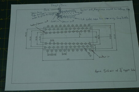
From the research I did it appeared that heavy wall 3/16” copper tube was preferable the other important requirement is for the tube to be as long as possible.

I had a couple of ideas for how to improve the insulation of my future steam generator and whilst discussing this at a model boat group meeting Alan came up with the brilliant idea of using a vacuum to insulate the inner from outer.

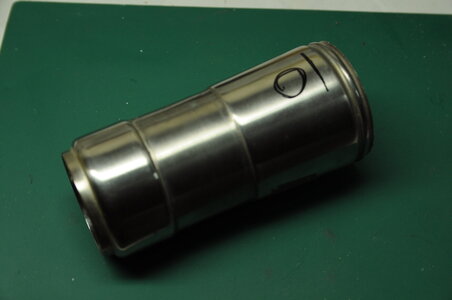
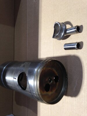
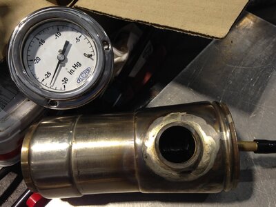
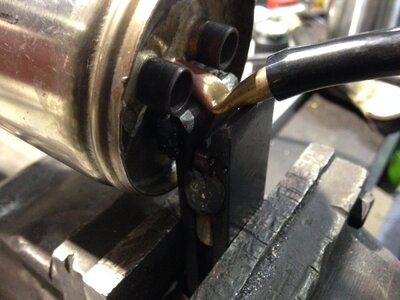
I found an old stainless steel vacuum flask that looked like the right size, checked it in the hull to make sure. Holes were cut into the vacuum flask where required then bushes silver soldered in. This really tested my silver soldering ability.


DSC_0945.JPG

DSC_1620.JPGIMG_0608.JPGIMG_0609.JPG
Successful test, reading after overnight vacuum test holding at 27" of mercury that's as high as our vacuum pumps would go. 30" of mercury is an absolute vacuum.


IMG_0612.JPG
Crimping vacuum line while drawing a vacuum, I have no way of knowing if the crimp is good!


DSC_1633.JPG
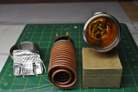
Inner coil, end cap and some aluminium backed insulation, ready for installation.


p024.JPG
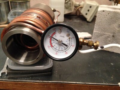
Inner and outer coils joined and being hydraulically tested holding at 150 PSI.
Stainless end cap in position.
Outer coil provides pre-heating.

Thanks for looking in.
Cheers,
Stephen.
 
Thats just beautiful Steve, my plans arrived this morning and I just have to decide what scale I will use, and if I will power her or just have her for display, thank you for all the help and the info,

best regards John.
 
Back
Top