Black Pearl 1:50 ZHL

¿No lo tienes? ¿Porque no? ¿Tienes el equipo?
¿Tienes el equipo de ZHL? Llama Max de ZHL. Perhaps I should say this in English. I understand that Max at ZHL is pretty helpful to cover any deficiencies of his kits. Did you buy the kit fro ZHL and it had no instructions? Is that the problem?
 
So onward we go. This model definitely is one that a person wants to spend some extra time thinking about what to do when. There is a lot of potential to close something up like the lower deck to early and then have real problems doing something you forgot about under the deck.

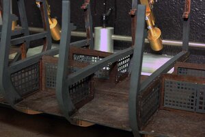
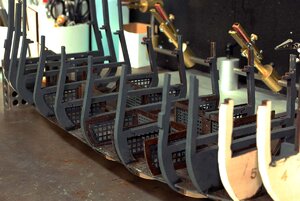
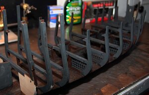
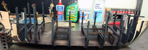
I spent quite a bit of time pondering the color of the frames but decided I should at least darken the walnut frames it just looks odd to have wood and then stark black to me.

bp050.jpg

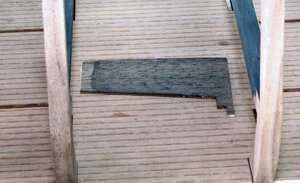
So I got the stain I mentioned above and did a test piece of the walnut deck. In the photo below you can see the stained piece lying on the deck and I have decided to go with a darker appearance.

bp051.jpg

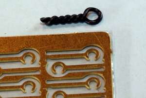
I decided to add the hangers for the lights on the lower decks. I was concerned about the brass hooks that come with the kit having sharp edges and damaging the magnet wire when installing the lights. The magnet wire is painted with a clear coating that insulates the wires. It’s tough stuff but even so you’ll want to be careful not to scratch it up or the lights might not work. After I downloaded the photo below from my camera the photoetch doesn’t look particularly sharp so it was probably unnecessary but I decided to go with it anyway. And the closed loops will hold the wire better anyway.

Edit: I can tell you from the work I've done since I'm glad I did these rings to hold the lights because there is just a lot of handling building this model and it would be easy to know the lanterns out of the hooks

bp052.jpg

I then went ahead and drilled the holes for the lantern hooks and with these I actually just screwed them in. If you make the hole the correct size the twisted wire acts like a screw and goes in really solid just like a screw does.

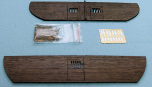
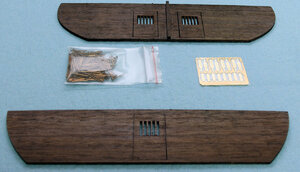
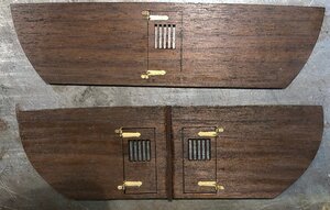
Edit: This is a place where I made a bit of a mistake. There are two bulkheads with doors that need to be attached to the framing. One fore and one aft. The aft piece with 2 doors on it needs to be attached before the two hangers for the lanterns. I didn’t figure this out till I was in the decorating stage. They are parts E-1 and E-2. The manual calls for this later in the build. It also calls for putting in the hooks for the lanterns later I just figured it’d be easier to do it now. This is the bulkhead I'm talking about

BP205.jpg

I also went ahead and painted the rest of the frames black to match the rest of the framing. If I had this to do over I would just paint the black before I even put them on. I also stained the deck with the black stain and then used 600 grit sandpaper to make it look worn.

bp060.jpg
 
I’m going to hijack my own thread for a second again and point out that I mostly work on this stuff at night and therefore most of the photos are taken with a flash and then get adjusted in photo shop, so the colors tend to be kind of all over the place. The last photo in the previous post was taken in natural light and is the actual color you would see if you were here. So if you think my model is changing colors regularly it really isn’t for the most part and I’ll tell you if I did actually change the color of something.

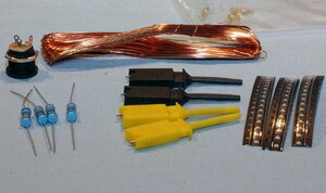
So on a Friday night. That’s when I usually have most of the night to myself, I started on the lanterns for the lower deck. Here are the parts that were included in the electrical bag. This is going to get pretty basic for people that don’t do electronic stuff.

First the copper wire is what is known as magnet wire. It's 28AWG in case you need more I ordered some extra which will be explained later. It appears to be bare wire but is actually coated with a clear really durable coating. Like a flexible varnish for lack of a better term. It’s kind of finicky stuff to work with. It’s tough which makes it hard to scrape off, so IMO the best way to use it is to solder pretty much all joints with it. The solder is hot enough to burn the insulation coating off of the wire. If I just want to touch the wire to a battery for testing for instance, I just tin the end of the wire with solder.

Also included are 330 ohm resistors, the plug socket for the power supply, 51 Surface Mount LEDS, and 4 test leads.

bp062.jpg

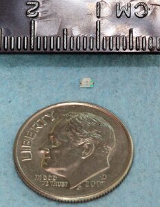
Near as I could tell from studying the plans the kit requires 29 LED’s so 51 is probably sufficient. These microscopic things like to magically disappear when you least expect it. Here’s a reference as to the size at about 1 ½ mm square.

bp064.jpg

This is something that if you don’t have any experience soldering, it might be worth it to look at Evan designs or a similar place and just buy leds already wired. I don’t know what it would cost but I assume Evan designs would put longer leads on their pico sized leds, or you could just extend the wires on theirs and avoid having to actually solder the leds. Or maybe see if you can find someone that solders well.

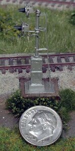
I’ve had quite a bit of experience with these little things and can tell you at first they seem like a cruel joke, but you can handle these with a few pointers. I built a bunch of signals with surface mount leds and much smaller magnet wire, and can’t say I like it, but it’s doable. There are actually 3 colored leds in the heads so there are 6 wires running down the mast in the signal below. These signals will definitely make you hate magnet wire.

bp063.jpg

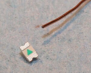
Here’s a closeup of the wire and what you’re wiring too. The metal tabs on the back of this is where the solder actually sticks.

bp065.jpgBP065

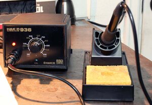
I’m not going to do a full soldering tutorial, there are plenty of those on the internet, but here’s some basics you need to know. You need a soldering iron with a fairly small tip. It helps in both being able to see your work, and not just burning up the LED. I highly recommend a soldering station like the one below. This is a Hakko 936. They're a pretty nice middle of the road soldering station. Probably the most important thing about soldering stations is they maintain a particular temperature.

BP066.jpg

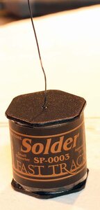
I also recommend a thin rosin core solder. I got mine from Fast Tracks which is a Canadian company that sells train stuff. The really thin solder makes it much easier to get just a tiny amount of solder where you want it. Make sure you avoid acid core solder. The acid not only makes a mess that’s hard to clean off, it also eats the tip of the soldering iron.

BP067.jpg

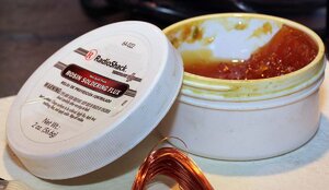
I also use rosin flux like below when I solder this kind of stuff. I soldered for years with just rosin core solder and did fine until I started working on smaller stuff like N scale railroad track. Believe me flux is you friend when soldering something this small. It actually makes normal soldering much easier as well. This is no longer available but it’s the type of paste flux I use. Similar products are available from the usual sources.

BP068.jpg

Continued in the post below
 
When I pulled the gizmos below out of the bag, I was a bit confused by what they were for. I’m pretty sure these are actually test equipment leads. Based on the pictures in the manual, the idea is you push on them so the little claw comes out, and then lock the claw around a wire etc.

BP069.jpg

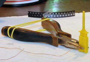
The instructions show placing a smd (Surface Mount Diode) in the claw of one of these clips. Then use pliers with a rubber band to hold it up while soldering.

BP070.jpg

I decided to give it a try. As it turns out these little clips, I tried one of each color, are actually magic. They make leds disappear right before your eyes. I never managed to get one to stay in one of these clips. I’m pretty sure there is one somewhere in the furnace and the dog wasn’t amused by being shot by some strange projectile while she was sleeping at my feet. I’m just kidding about the furnace and the dog, but I did shoot 3 of the smd’s off into oblivion.

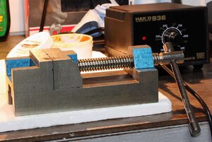
So my rather odd solution was to go back to what worked for me before. I have a small machinists vice. A machinists vice has jaws that run along a track which keeps the moving jaw from tipping therefore keeping the two jaws much more parallel to each other. This vice is about 2 inches(50mm) wide and 6” (300mm) long. I don’t know where I got it but I’d bet the Proxxon MS 4 Machine Vise would be just as good as long as it has metal jaws.

BP071.jpg

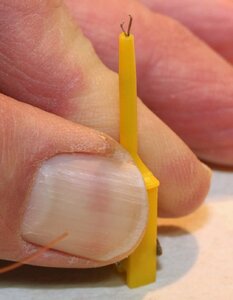
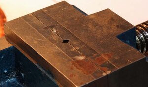
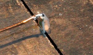
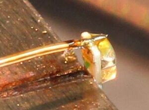
So I first put one ear in the vice as shown below. The tiny led makes the vice look massive.

BP072.jpg

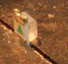
Next I put a tiny bit of solder on from the top side.

BP073.jpg

Then I tin the wire to melt the insulation off the very end and add a tiny bit of flux and solder the wire as seen below.

BP074.jpg

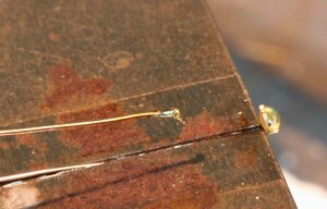
I then turn it sideways in the vice and clamp the wire holding the led with the other side up. Below you can see the tinned wire with a bit of paste flux, and the led on the right side of the vice.

BP075.jpg

And here it is soldered on.

BP076.jpg

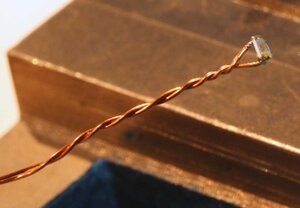
Then twist the wire with the led. If your solder joints are good, they will be strong enough, you can take the led in one hand and twist the wires with it. I do that as a test because if it can't hold up to that, it is probably going to fall apart while you’re trying to install it.

BP077.jpg

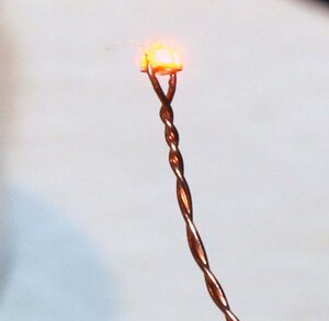
And then it’s wise to use a battery and make sure you didn’t kill the led in the process of putting it together. I did cook one led myself because I got in a hurry and put way to much heat and solder to it. Here’s one being tested.

BP078.jpg

On to assembling lanterns tomorrow.
 

Attachments

  • BP073.jpg
    BP073.jpg
    29.8 KB · Views: 7
When I pulled the gizmos below out of the bag, I was a bit confused by what they were for. I’m pretty sure these are actually test equipment leads. Based on the pictures in the manual, the idea is you push on them so the little claw comes out, and then lock the claw around a wire etc.

View attachment 179124

The instructions show placing a smd (Surface Mount Diode) in the claw of one of these clips. Then use pliers with a rubber band to hold it up while soldering.

View attachment 179125

I decided to give it a try. As it turns out these little clips, I tried one of each color, are actually magic. They make leds disappear right before your eyes. I never managed to get one to stay in one of these clips. I’m pretty sure there is one somewhere in the furnace and the dog wasn’t amused by being shot by some strange projectile while she was sleeping at my feet. I’m just kidding about the furnace and the dog, but I did shoot 3 of the smd’s off into oblivion.

So my rather odd solution was to go back to what worked for me before. I have a small machinists vice. A machinists vice has jaws that run along a track which keeps the moving jaw from tipping therefore keeping the two jaws much more parallel to each other. This vice is about 2 inches(50mm) wide and 6” (300mm) long. I don’t know where I got it but I’d bet the Proxxon MS 4 Machine Vise would be just as good as long as it has metal jaws.

View attachment 179126

So I first put one ear in the vice as shown below. The tiny led makes the vice look massive.

View attachment 179127

Next I put a tiny bit of solder on from the top side.

View attachment 179129

Then I tin the wire to melt the insulation off the very end and add a tiny bit of flux and solder the wire as seen below.

View attachment 179130

I then turn it sideways in the vice and clamp the wire holding the led with the other side up. Below you can see the tinned wire with a bit of paste flux, and the led on the right side of the vice.

View attachment 179131

And here it is soldered on.

View attachment 179132

Then twist the wire with the led. If your solder joints are good, they will be strong enough, you can take the led in one hand and twist the wires with it. I do that as a test because if it can't hold up to that, it is probably going to fall apart while you’re trying to install it.

View attachment 179133

And then it’s wise to use a battery and make sure you didn’t kill the led in the process of putting it together. I did cook one led myself because I got in a hurry and put way to much heat and solder to it. Here’s one being tested.

View attachment 179134

On to assembling lanterns tomorrow.
I'm totally befuddled. Never done anything like this before. I'll be following you. Hope I won't be burning up all my leds.
 
I'm sure you'll figure something out.

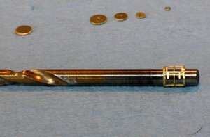
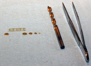
Next up was the brass portion of the lantern. I decided to stick with bare brass being as this is a fantasy ship anyway. I used a #21 drill a pair of tweezers and the parts below for each lantern.

BP079.jpg

I wrapped the brass cage around the #21 drill bit, which is 3.97mm diameter,

BP080.jpg

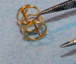
Then bent the inner tabs in opposite directions to hold it in place.

BP081.jpg

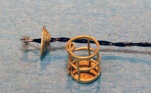
The two wires on the led have to be fed through the holes in the 4 washers to make the top. I glued this all together with a railroad type glue sold by Woodland Scenics here in the US called “Scenic Glue”. It pretty much regular white pva glue of some sort. It’s really tacky like Eileens tacky glue. What I like about it is it dries absolutely invisible. It has a flat finish when dry so there’s no shiny spots.

BP082.jpg

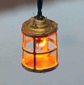
And here’s the finished product. These look great on the ship.

BP083.jpg
 
Next I assembled the walls for the lower deck. The bars for the jail cells are photo etched brass. I just painted it flat black. I find it odd that the brass for the bars is slightly bigger than the holes cut in the wood parts. You could I suppose file the brass down or make the holes larger and glue the bars in the center of the wood partition, but I decided to do as shown in the manual and just glue them on one side.

bp085.jpg
bp084.jpg
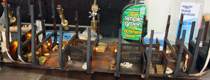
I stained the wood portions with black stain to darken them and put on a light coat of amber shellac. The photos above and below I adjusted in photo shop to appear about the way it looks in real life.

bp086.jpg
 
In reference to decorating this lower deck there are tons of improvements that could be made. Some I think might be worth it others probably not. As mentioned above the bars could be centered in the partitions, or maybe even better walls could be built to sandwich the bars which would look far better. I considered putting a groove in the top of the beams where the gun deck attaches and run the wires basically on top of the beam to hide them under the above deck. IMO it comes down to what your goal is and how much time you want to spend on it. I doubt anyone who actually sees this model in person will look close enough to see the wires that are painted black running along the roof or notice the bars aren’t centered in the walls. But it’s something to think about.

I also put some consideration into the possibility of making it more true to what an actual ship might have in it. There is no were to cook in this thing. At the same time I doubt anyone will ever look at this model and seriously critique the accuracy.

So I got back to work on this after a bit of a break and the first thing I discovered was I made a mistake. Parts E1 and E2 are fore and aft walnut bulkheads that need to be added. The rear bulkhead needs to be installed before the hangers for the lanterns. I edited the earlier posts to reflect this.

BP205.jpg

I did some sanding on the deck to give it more of a warn appearance.

BP200.jpg

Next up was the decorations for the lower deck. There are two piles of skeletons. They have a bottom that is about 1/16th of an inch thick and it needs to be sanded off. It’s pretty easy to do with a rotary tool and sanding drum as shown in the instructions. I also cut out the single skeleton and painted it all white.

BP202.jpg

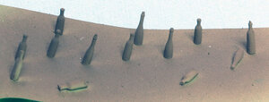
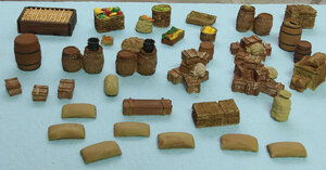
Then it was painting bottles and miscellaneous boxes etc. Here is what I came up with.

BP201.jpg

BP203.jpg

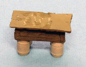
I also created this little carpenters table by cutting the top off of one of the fruit and vegetable stand decorations and adding some small barrels below it for legs.

BP204.jpg
 
I got the hinges put on the fore and aft doors.

BP-220.jpg

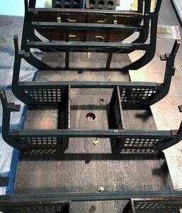
On Tuesday night I had a little more time so I got the fore and aft bulkheads in and hung up the lanterns. This is a pretty fiddley project and I’m glad I did it before starting on other decorations. It takes a lot of flipping it over etc to get the wiring done. I used Weld Bond to glue the wires to the beams and then painted over it with flat black to cover the glue.


BP-222.jpg
 
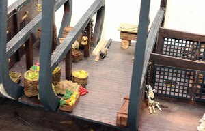
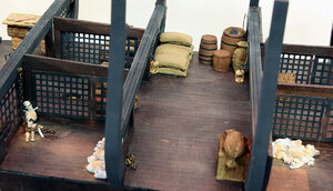
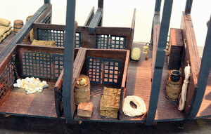
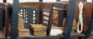
I pretty much decorated the lower deck to match what the instructions called for.

BP225.jpg

BP226.jpg

BP227.jpg

I left some areas a little more open so I could add other items later from the side, like sea monsters figures other skeletons etc. but tried to get the it to look like it’s got a good amount of random stuff in it. These photos give a better idea of what a person will really see.

BP228.jpg

BP229.jpg

BP230.jpg

And here’s a photo of the lanterns lit up. I wanted to be sure these were all on before I put the above deck on. It would be really hard to replace or repair these lights with the deck on.

BP231.jpg
 
Absolutely. I can get lost in all those little details.
 
Thanks for the compliments

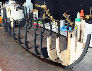
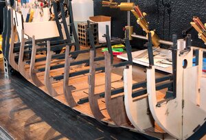
I went ahead and added Bulkhead 15, that’s the rearmost one in the photo below. The instruction tell you when you’re assembling the bulkheads in the beginning that you can leave these last two frames off, but don’t really tell you when to put them on. This one sits under the second deck so it has to be on before the deck above is installed.

BP232.jpg

Next up I put a coat of my black stain on the 2nd deck and then a coat of shellack like I did the lower deck.

BP234.jpg

While that was drying I started prepping the parts in the photo below. I'm not as patient as I might ought to be. One trick I learned over the years id to work on groups of parts at a time. That way when something needs to just sit I have something else to keep me busy while I wait.

BP233.jpg

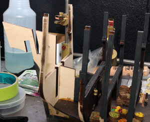
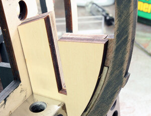
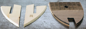
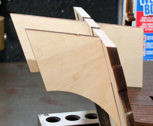
The instruction show gluing parts 20 on each side of the front at this point, however these will need a fairly radical flare angle so I sanded the taper before gluing them on. Here is what I’m talking about.

BP236.jpg

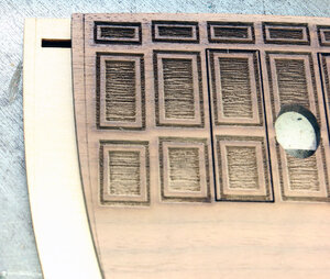
The front bulkhead is made up of 2 pieces. You can see the extra score line on the front of the decorative piece. I assume this is a fairing line. Why there is a similar score on the piece behind is a mystery to me, you definitely would not want to fair each part individually.

BP235.jpg

So I glued them together and faired the top as seen below. We’ll see if this was a mistake later I bet. You can also see how I faired part 20 on the left.

BP243.jpg
 
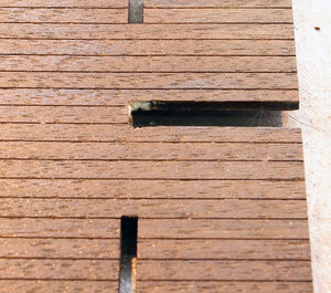
So next I went back to the 2nd deck and decided it was time to install it. So here’s where thing went off the rails a little bit. First I tried to test fit the deck and it simply didn’t fit. I finally deiced the keel is about 2 millimeters shorter than it is supposed to be. If you go back to the beginning of the thread you’ll see the photo of the play in the false keel at the beginning. I’m guessing when I tightened up the joint I slightly shortened the ship. The frames still fit fairly well but I had to trim the slot in the deck to get it to fit.

EDIT: This appears to be a flaw in the cutting of either the keel of the deck. I personally think the deck is what is cut wrong. @Ahoy All had the same issue on his deck even after reading this and not tightening up the joint in the keel. This modification did not hurt anything going forward in the build. I might have had to sand a little on the side of the deck but no real issues.

BP237.jpg

At this point I glued and managed to get the deck down in place without breaking anything. I took the photo below.

BP238.jpg

What you can’t see in the photo is after about half an hour, I noticed that the large deck portion was not against the frames. Fortunately the glue wasn’t completely set because I had to break the deck loose and re-glue it.

It was at this point I came up with the idea that I should glue I the narrow part first, making sure to have it all the way against the frames. Then immediately glue in the wider portion to make sure I could get everything to fit. It took some wrestling but here’s the finished product.

BP244.jpg

I did put a small amount of glue under the “removable” panels. I’m sure I can get them out without damaging them (significantly anyway) You really need the panels in place to make sure you don’t close up the holes. You could do a lot more fitting than I did ahead of time but I chose the more forceful approach.

BP245.jpg
 
Last edited:
I did put a small amount of glue under the “removable” panels. I’m sure I can get them out without damaging them (significantly anyway)
Too late now Jodie but for another time sake maybe, if you glue paper to one part and glue the other part to the other side of the paper, it should be easy to take apart, leaving a thin layer of paper on both parts that can easily be sanded away.
 
Poul that's a great idea I'll keep that in the memory bank for the future for sure.

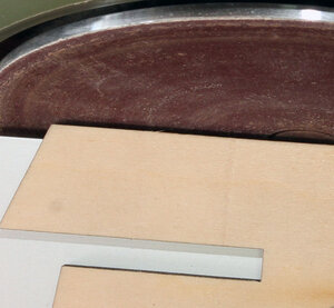
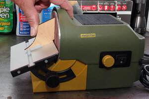
Next I turned my attention to the canted frame that goes at the rear of the ship. The top of the frame needs to be sanded to match the false keel so the deck of the main cabin can set flat. I used one of the side pieces to set the angle on my disk sander.

BP239.jpg

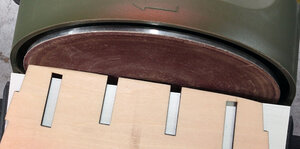
I then sanded the top of the frame to match this angle. This might be self explanatory but I’m going to show it anyway. In the photo below you can see the gap between the part and the sanding disk.

BP240.jpg

I sanded the top of the frame till the gap just disappeared and then stopped. This will give you the correct angle without shortening the part. I also wanted to point out the gap you see now is because the top of the frame has a slight curve for the deck camber. Make sure you don’t just sand it flat and take the arc out.

BP241.jpg

Here it is in place. I wanted to point out if I didn’t have the disk sander I would have lightly tack glued the end pieces I used to set the angle on the disk sander to the frame and used them as a reference to sand the frame to the correct angle with a sanding block.

BP242.jpg
 
Back
Top