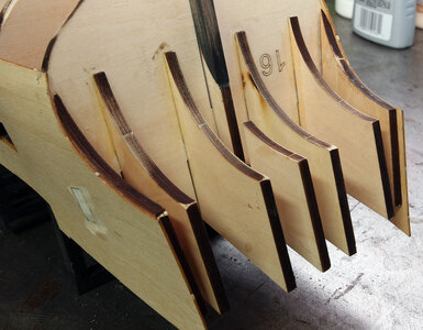
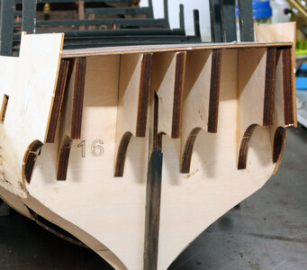
Black Pearl 1:50 ZHL

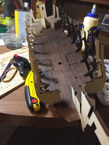
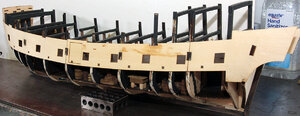
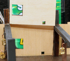
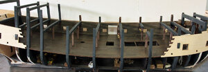
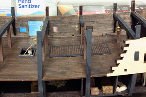
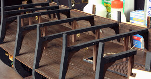
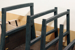
Next up I glued the front pieces in place and then went to work cleaning and painting the upper beams for the second deck. On the next Saturday I spent most of the day soldering up more lanterns and installing them. I previously showed the lantern construction so I didn’t document that again. Here’s the ship with the beams, pillars and lights in place.
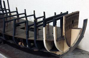
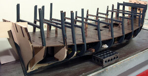
BP247.jpg

BP246.jpg
I had to chuckle after I got this done I noticed a note, that I interpreted to mean "you could sand the pillars to make them round which would look better." I thought to myself that this could be a neat idea, but if you were going to make the pillars round it would be good to think about that before doing the lower deck. Not to mention doing that after installing the pillars like I have would absolutely result in breaking a lot of parts.. Well maybe next time if I build the inside of a ship again. It would look nice IMO to turn the center of the pillars so they are round just as an added detail.

So my next decision was to glue the top of the rear frames on. The instructions tell you to do this, but it might be better to leave them off for a bit. It’s a tough call IMO because they do reinforce the top of the frame for when you flip it over.

Edit; After moving forward in the build I highly recommend gluing the aft of the three cross beams in place. The forward 2 might still end up being in the way, but the aft one makes it so you can flip the ship over and work on the bottom without breaking anything. It's interesting the manual tells you to glue these on in step 105 but you never see them in another photo till you get to step 189.
BP248.jpg
 
Vic, took me a while to make sense of it. We have to do some surgery on the white cable that is in with the remote control. The black power jack goes into the coffin from the wall transformer. It powers the little rectangular white thing which gets attached to the spring loaded pins on the top of the coffin. The pins are then placed under the keel where there are four brass strips. Three of the brass strips are connected to resistors and the negative wire bundles, one from each deck. The 4th strip is connected directly to all of the positive wires.

I'll detail how to do that when I get there. I haven't gotten to the coffin it's the last step in part 1. I kept thinking I was missing a circuit board after about 15 minutes I finally figured out it was the one on the end of the white cable with the plastic removed. The instructions actually show that.
 
Last edited:
My plan at this point is to go with a ghostly pearl white with a greenish patina on the decorations, but I really won't make that determination for sure till I get the hull color settled on. I still have a lot to do before external decorations. I answered the question about the back wall in your build log.

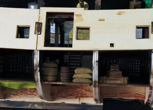
I then started on the outside skin I’ll call it. This is 1mm thick ply and was a little tricky. I started with the center section. I filed the notches where they go to the tabs on the frames to get it to fit they were a little tight, the panel wouldn't lay flat. Next I added the rear section. The distance from the notch in the front to the rectangular hole on the rear that goes around the tab was too long. I’m guessing by the approximate 2 millimeters I was short to begin with, I filed the notch in the front first to get it aligned with the tab and the center piece. Then I ended up filing the front and top of the diagonal hole in the back to make it square with the center section and glued it on. Next I added the front section in a similar manner.

BP249.jpg

The front is where I ran into more of a problem. There are three tabs on the front of this piece. The instructions say to trim the ends of the tabs and put them in the rabet. I was concerned about the shape of the bow and so I found the deck for the front and compared the shape of it in place with the curve formed by the tabs. They weren’t even close and the tabs wanted to come up so the top tab was about 3/8 inch above the deck it should sit under. Getting it down where it belonged forced the skin off of the forward frame. After a little coercion I finally decided the best bet would be to make a filler block for the bow. So I glued the skin to the forward frame and then just cut off the tabs. I’ll create a filler block before it’s time for planking.

BP250.jpg

Next I glued parts L and LC together. I finally decided it doesn’t matter which you glue on which side. They're exactly the same shape just different thicknesses.

BP251.jpg

The manual has a lot of photos but often leaves me wondering if it’s time to do something because the photos often have parts installed that you weren’t told to install yet. If there were more written instructions it wouldn’t be much of an issue, but I keep finding myself seeing parts attached and wondering where I missed that. I bring it up because looking ahead in the instructions adding these panels and the planking on the back wall of the gun deck are shown being done after the barrels and hammocks are in place. I definitely recommend waiting on the decorations on the deck till after the inner gun deck bulkhead is done.

I also found myself thinking it would be easier to add the planking on the bulkhead without the upper beams in place. After thinking about it a bit I realized that the lights need to be in first because the wire go down by the ends of these pieces, and it would be hard to leave them hanging and do the installation after the bulkheads are done.

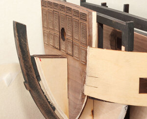
The reason the lights have to be in is because the wires take up some of the space for the blocks as seen below. Also here’s a un sanded block. You can see it barely fits which wouldn’t leave any room for the wiring.

BP252.jpg

So I sanded it down enough on the side to leave a gap for the wire.

BP253.jpg

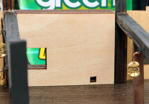
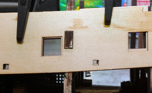
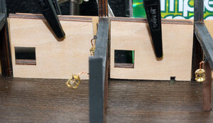
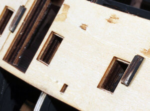
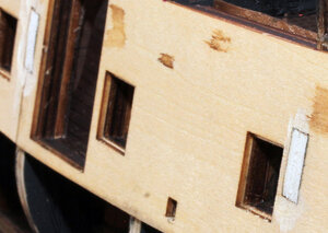
There is one other issue you have to watch for. In the photo below you can see the gun port and sweep port on the inner part are lined up with the holes in the skin on the left. This took quite a bit of sanding to accomplish. Y

You can see how far off the one on the right is. I had to do a considerable amount of sanding on nearly every piece to get these to line up.

BP254.jpg

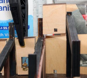
It took about an hour to get all of the pieces sanded so everything lined up. That was using a disk sander. I was concerned that I just got the skin on the sides on wrong, but they really can’t be nearly that far off. I considered that the deck might be mis-positioned, but it is also all the way down. I think a big part of the reason there is a lot of material that needs to be removed is a combination of not taking into account that the wires would be in the way, and the fact that the two layers create a 7MM thick part and it has to lean back toward the center of the ship. So it’s at least partly just the fact that you can’t easily cut compound angles on a laser cutter. Wat I mean is the gun port is cut the correct distance above the deck but when you lean the part back the gun port moves up so it's no longer aligned. This photo gives an Idea how much I sanded the parts to make them fit.

BP255.jpg

I’m not showing this to bash ZHL. I just wanted to say that if I didn’t have a disk or belt sander I would use a saw to remove the bulk of the necessary material. I’ve seen several builds on the internet, and even the instructions where there was quite a bit of mis-alignment of parts. The instructions just tell you to glue these in and move on. If you just glue these in you’ll have a nightmarish task trying to fix the gun ports etc. on the side of the ship, Not to mention you'd likely damage the wires on the lanterns.

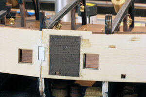
In the photo below you can see that I placed the forward bulkhead on the wrong side of the beam. I didn't figure this out till later. I had to sand the side piece to fit. This doesn't make any difference in the long run, but you can save yourself some sanding by gluing the front bulkhead on the back side of the beam..

BP256.jpg
 
Last edited:
My plan at this point is to go with a ghostly pearl white with a greenish patina on the decorations, but I really won't make that determination for sure till I get the hull color settled on. I still have a lot to do before external decorations. I answered the question about the back wall in your build log.

I then started on the outside skin I’ll call it. This is 1mm thick ply and was a little tricky. I started with the center section. I filed the notches where they go to the tabs on the frames to get it to fit they were a little tight, the panel wouldn't lay flat. Next I added the rear section. The distance from the notch in the front to the rectangular hole on the rear that goes around the tab was too long. I’m guessing by the approximate 2 millimeters I was short to begin with, I filed the notch in the front first to get it aligned with the tab and the center piece. Then I ended up filing the front and top of the diagonal hole in the back to make it square with the center section and glued it on. Next I added the front section in a similar manner.

View attachment 181770

The front is where I ran into more of a problem. There are three tabs on the front of this piece. The instructions say to trim the ends of the tabs and put them in the rabet. I was concerned about the shape of the bow and so I found the deck for the front and compared the shape of it in place with the curve formed by the tabs. They weren’t even close and the tabs wanted to come up so the top tab was about 3/8 inch above the deck it should sit under. Getting it down where it belonged forced the skin off of the forward frame. After a little coercion I finally decided the best bet would be to make a filler block for the bow. So I glued the skin to the forward frame and then just cut off the tabs. I’ll create a filler block before it’s time for planking.

View attachment 181774

Next I glued parts L and LC together. I finally decided it doesn’t matter which you glue on which side. They're exactly the same shape just different thicknesses.

View attachment 181775

The manual has a lot of photos but often leaves me wondering if it’s time to do something because the photos often have parts installed that you weren’t told to install yet. If there were more written instructions it wouldn’t be much of an issue, but I keep finding myself seeing parts attached and wondering where I missed that. I bring it up because looking ahead in the instructions adding these panels and the planking on the back wall of the gun deck are shown being done after the barrels and hammocks are in place. I definitely recommend waiting on the decorations on the deck till after the inner gun deck bulkhead is done.

I also found myself thinking it would be easier to add the planking on the bulkhead without the upper beams in place. After thinking about it a bit I realized that the lights need to be in first because the wire go down by the ends of these pieces, and it would be hard to leave them hanging and do the installation after the bulkheads are done.

The reason the lights have to be in is because the wires take up some of the space for the blocks as seen below. Also here’s a un sanded block. You can see it barely fits which wouldn’t leave any room for the wiring.

View attachment 181776

So I sanded it down enough on the side to leave a gap for the wire.

View attachment 181777

There is one other issue you have to watch for. In the photo below you can see the gun port and sweep port on the inner part are lined up with the holes in the skin on the left. This took quite a bit of sanding to accomplish. Y

You can see how far off the one on the right is. I had to do a considerable amount of sanding on nearly every piece to get these to line up.

View attachment 181778

It took about an hour to get all of the pieces sanded so everything lined up. That was using a disk sander. I was concerned that I just got the skin on the sides on wrong, but they really can’t be nearly that far off. I considered that the deck might be mis-positioned, but it is also all the way down. I think a big part of the reason there is a lot of material that needs to be removed is a combination of not taking into account that the wires would be in the way, and the fact that the two layers create a 7MM thick part and it has to lean back toward the center of the ship. So it’s at least partly just the fact that you can’t easily cut compound angles on a laser cutter. Wat I mean is the gun port is cut the correct distance above the deck but when you lean the part back the gun port moves up so it's no longer aligned. This photo gives an Idea how much I sanded the parts to make them fit.

View attachment 181779

I’m not showing this to bash ZHL. I just wanted to say that if I didn’t have a disk or belt sander I would use a saw to remove the bulk of the necessary material. I’ve seen several builds on the internet, and even the instructions where there was quite a bit of mis-alignment of parts. The instructions just tell you to glue these in and move on. If you just glue these in you’ll have a nightmarish task trying to fix the gun ports etc. on the side of the ship, Not to mention you'd likely damage the wires on the lanterns.

The photo below shows that they failed to take into account the thickness of the front bulkhead. So this part had to be sanded a good 1/8th of an inch.

View attachment 181780
Yowsers! That’s another part I’m not looking forward to.
 
My next mission was to work on the planking on the gunwale. First thing I had to do was figure out what strips of wood to use. In the photos they looked thin so that narrowed it down to 2 bundles, but it wasn’t clear which was being used. So I counted the number of planks in the photo from top to bottom which is 9. Then I measured the height of the wall, which is about 43MM. So I divided 43 by nine and got a little less than 5mm. So I decided it must be the 5mm wide strips I should be using. The other strips are 3.75mm.

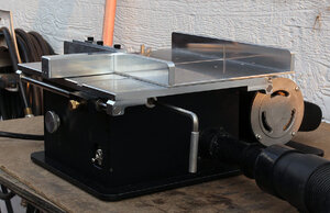
There are a lot of sweep ports along the deck and I thought about trying to cut these from the plank before installing it, but due to the lack of good access because of the main deck beams, decided it would be best to just glue the plank over the hole and then drill and file them afterward. So I tried to glue the lower plank along the deck. The 5mm width with a super thin plank made it really hard to bend the plank to the side. So Back to the drawing board as they say. I considered just painting everything black, that would be the easy way and it’s not going to be very visible anyway, but that felt a little to sub standard to me. So what I decided to do is cut the planks to 2 inch (50mm) lengths and plank it with those. That also gave me an excuse to try out the sliding table I bought with the Byrnes saw, which worked awesome.

BP257.jpg

So I got the first 2 layers of planking in the first night.

BP258.jpg

I finished up the planking and hit it with some of the black stain so it all matches the next evening.

BP259.jpg

I started on the parts that go on the first deck. I painted the frame for the grate and stairway black and then stained and finished the grate. I had a little trouble finding the stair treads. The instructions aren’t real clear. The treads are laser cut parts on one of the sheets. Here they are in place.

BP260.jpg

I stained the knees that go under the beams and glued them in place. You can leave out the front 2 and aft 2. The instructions mention that. It doesn’t really matter it's not likely anyone will see them anyway so I left them out.

BP261.jpg
 
I also stained the buckets and barrels with black stain. I wanted it to be random and inconsistent so instead of painting it on, I just put a little bit in a plastic bag rolled the stuff around in it.

BP262.jpg

And here’s the results

BP263.jpg

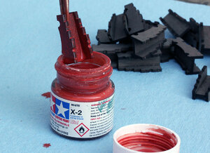
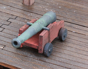
So I spent quite a few days thinking on how to decorate the canon. Being as I’m going with the weathered look for the whole build I decided to try a faded red with patina on the barrel. I used Tamiya acrylic Nato Black paint on the barrel. Then the green patina is just weathering powder.

I made a wash of dark red paint about 80% water and 20 percent paint and then dipped the carriage in it.

BP264.jpg

And the final result

BP271.jpg

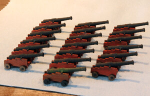
I will add more detail before I mount the canon this was just to figure the process out. I then did 18 more canon that way.

BP265.jpg

Edit: I realized at a later date that I glued the carriages backward, they should be narrower in the front instead of the back. So, I have taken them apart, they popped right apart easily, and will put them together correctly after I finish the lower planking.

At this point I stopped and got the manual out. I do this periodically to figure out what I have done or missed etc. As I’ve mentioned before the photos in the manual at times seem to be kind of all over the place. Technically I’m at step 135 in the manual. This is one of those better have everything the way you want it before you go forward steps. It’s putting the Main deck in.

Now I know I’m not really ready because I haven’t put much of anything on the gun deck. So according to the instructions I skipped the following steps.

97 & 98 which is the 2 hammocks in the instructions. Not sure I want to do those at all but didn’t see a need to do them that early.

109 which is barrels and boxes that I didn’t want to put in until the guns are in place.

110-111 I really did this but didn’t cross it off because it’s the bow where I cut the wood off and I still need to build some filler blocks.

And last Step 120 which is the canons, canon balls etc..

So I have everything together to decorate the gun deck with the exception of ropes to hold the canons and any other minor details I want to put on this level.
 
Last edited:
What occurred to me at this point is, do I really want to mount the canons and have to try and work around them when I’m planking. It really is something of a problem. The gun deck is deep enough it would be exceptionally difficult to detail it with the main deck in place. At the same time doing all of the planking work with 18 canons sticking out the side would be a nightmare. I’d be constantly hitting them and knocking them back into the gun deck etc.

So I did a lot of studying of the photos and how the sides are planked etc. And my final conclusion is there is no reason I can’t just plank the lower portion of the ship before finishing the gun deck, and putting the main deck on. I believe I can add the bracing at the stern with the aft portion of the main deck in place at least temporarily. After which point I can actually plank both the first and final layer from just below main deck level all the way to the bottom before I have to put on the main deck. So I won’t be knocking the guns out while doing planking. I also won’t have to try and sand around them. I would like to note I don’t consider this a design flaw it’s just an inherent problem with building the inside of a model.

So right or wrong that is the direction I’m going. One big thing I made note of is the wiring for the lanterns in the captain’s cabin and the stern lanterns needs to be in place before I close up the bottom. I’m a little confused rite now about how the stern lanterns are supposed to be wired. There appears to be only 2 wires run to them. I might have to send Max an e-mail and ask if that is a series or parallel setup for those led’s. I’m guessing they will be in parallel, It’s just odd that all of the other led’s are in parallel but have individual wires going to the bottom of the ship.

So I switched gear and started prepping for planking. First thing was dealing with the hole in the side of the ship. For some reason there is a large hole in the port side of ship. It appears to be a large door or ramp to the gun deck. However; going through the manual about half the photos have a hole and about half don’t. Not in any particular order, even the last 2 photos in the first part manual, one shows a hole and the other shows it planked over. Either way I know I don’t want the hole there so I put the part in like shown in step 147. Here’s what I’m talking about.

BP267.jpg

BP268.jpg

I also got out the flex shaft for my Dremel and sanded down the tabs on the frames that stick through the skin.

BP269.jpg

Here they are ground down.

BP270.jpg

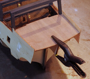
At this point I decided the rear structure needed to be strengthened so any planking back here was solid. I got out the deck of the Captain’s cabin and set it in place. Once again like with the main deck when attaching the Walnut ribs I didn’t glue it in just held it in place with a clamp.

BP272.jpg

I then flipped it over and glued in the supports for the deck. These aren’t really supports at this point because as the instructions point out they are actually a little short of reaching the deck. The instructions tell you to fill the gap under the deck later on.

BP273.jpg
 
Did you find anywhere how many lights to have on the main deck, including the captain's cabin? I tried to count them, but it wasn't clear to me.

I've decided there are supposed to be 9 on the main deck including the 3 stern lanterns. I believe there are 4 inside the captains cabin, 2 on the front wall of the captains cabin that light the deck, and the three stern lanterns. Somewhere in the instructions it says to run 9 pairs of wires to the captains cabin.

So I think based on the manual it's 8 on the lower deck, 11 or 12 on the gun deck and 9 on the main deck for a total of 28 or 29.
It’s a good thing they give us extra leds.
 
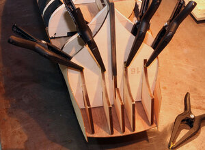
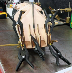
The real purpose though of placing the deck in is to adjust the sides to the correct angle. These outer two pieces need to be sanded to match the curve of the hull at the bottom (Top in the photo). In the photo below the brass bar clamp is holding the outsides of the 1mm skin against the deck so the plywood parts are at the correct angle.

BP274.jpg

After I got this put together I began questioning if there is any reason not to glue this portion of the deck on. I’ll have to look at the manual in that regard.

BP275.jpg

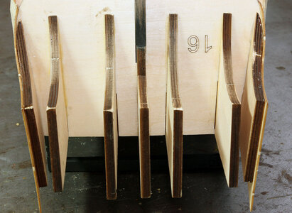
And lastly notice the outer plywood parts don’t actually match the size of the outer skin. The side of the part against part 16 needs to be flush and based on the photo in the manual it should match the arc along the skin. SO that leaves it long on the back end and top. I’m not going to do anything with it at this point I assume it’ll become clear if it needs to be shortened or not in the near future.

BP276.jpg

I came to the conclusion that there was no reason not to attach the floor of the captains cabin, So I glued it up to strengthen the rear structure.

BP283.jpg
 
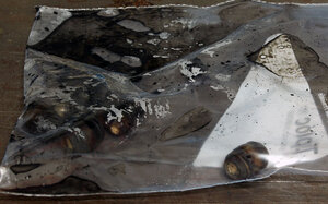
When I pulled the gizmos below out of the bag, I was a bit confused by what they were for. I’m pretty sure these are actually test equipment leads. Based on the pictures in the manual, the idea is you push on them so the little claw comes out, and then lock the claw around a wire etc.

View attachment 179124

The instructions show placing a smd (Surface Mount Diode) in the claw of one of these clips. Then use pliers with a rubber band to hold it up while soldering.

View attachment 179125

I decided to give it a try. As it turns out these little clips, I tried one of each color, are actually magic. They make leds disappear right before your eyes. I never managed to get one to stay in one of these clips. I’m pretty sure there is one somewhere in the furnace and the dog wasn’t amused by being shot by some strange projectile while she was sleeping at my feet. I’m just kidding about the furnace and the dog, but I did shoot 3 of the smd’s off into oblivion.

So my rather odd solution was to go back to what worked for me before. I have a small machinists vice. A machinists vice has jaws that run along a track which keeps the moving jaw from tipping therefore keeping the two jaws much more parallel to each other. This vice is about 2 inches(50mm) wide and 6” (300mm) long. I don’t know where I got it but I’d bet the Proxxon MS 4 Machine Vise would be just as good as long as it has metal jaws.

View attachment 179126

So I first put one ear in the vice as shown below. The tiny led makes the vice look massive.

View attachment 179127

Next I put a tiny bit of solder on from the top side.

View attachment 179129

Then I tin the wire to melt the insulation off the very end and add a tiny bit of flux and solder the wire as seen below.

View attachment 179130

I then turn it sideways in the vice and clamp the wire holding the led with the other side up. Below you can see the tinned wire with a bit of paste flux, and the led on the right side of the vice.

View attachment 179131

And here it is soldered on.

View attachment 179132

Then twist the wire with the led. If your solder joints are good, they will be strong enough, you can take the led in one hand and twist the wires with it. I do that as a test because if it can't hold up to that, it is probably going to fall apart while you’re trying to install it.

View attachment 179133

And then it’s wise to use a battery and make sure you didn’t kill the led in the process of putting it together. I did cook one led myself because I got in a hurry and put way to much heat and solder to it. Here’s one being tested.

View attachment 179134

On to assembling lanterns tomorrow.
Hi,

Following along with interest as I have a Black Pearl ordered.

What temp did you set the solder iron too?
 
I have it set at about 750F degrees (400C). To be honest though it might be set a little high, I didn't really think about it and the last time I was soldering I was building railroad turnouts which typically need more heat because of the size of the rail. Personally I've always had better luck with soldering a little hot but you have to be fairly quick or you burn stuff up.

I still need to do my captains cabin LEDS. I'm going to try to make a video of me soldering these, given the problems others are having. I'm sure it'll be a lousy video, but I think I can convey the information that matters.
 
Back
Top