Black Pearl 1:50 ZHL

yikes, 750F .... seems like that would burn out the LEDs.
Apparently it works though.

A video of the soldering job would be great help. Thumbsup
 
400 degrees will burn up an led if you hold it on the joint too long. Far more electronics are damaged by people using too cool of an iron and holding the iron on the joint to long, than by using too hot of an iron. A person should be able to solder a wire to an led in a couple seconds. 2 seconds at 750 degrees won't heat a part up like 20 seconds at 400 degrees.

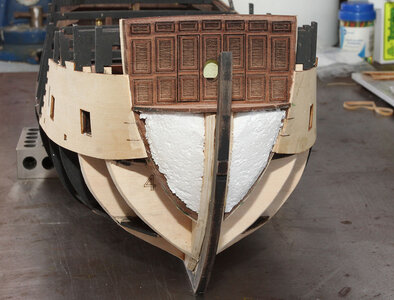
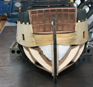
So next up I switched to preparing the bow for planking. I took some Styrofoam I had lying around and shaped it to fit in the bow behind where the skins I had previously cut off where supposed to be attached. I just roughly cut the Styrofoam to fit in the recess and the freehand carved to fit between the deck, the stem, and the bulkhead.

BP277.jpg

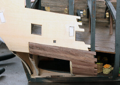
I then grabbed a reject Alaskan Cedar plank that just happened to be on the workbench and reconstructed the upper skin. I cut 3 full width planks placing them just under the forward deck and then placed the third below the second in the front and matched the lower edge of the skin in the back. I then filled the gap with a sliver piece. My main thought was to do something similar to the original and have it match on both sides.

BP278.jpg
 
Last edited:
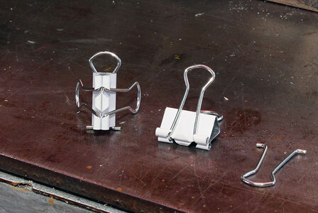
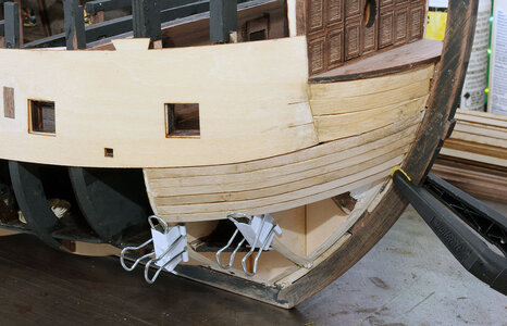
Next up it was time to do some planking. So I got my clamps out. Most people have seen this I would imagine but figured it wouldn’t hurt to show it. These clamps are just Binder clips from the office supply store. You can take the handles off of one and place it I another clip to make a planking clamp.

BP279.jpg

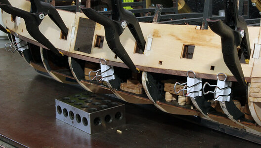
In the photo below you can see how the binder clips work.

BP280.jpg

The instructions are really ambiguous about how many planks to put where. I spent a lot of time going back and forth through the photos in the manual trying to figure out how many of what type of planks went where. I can’t say I really figured it out so much as I just developed a strategy and went for it. I was working on the starboard on the front and back and the stern on the port side lower deck area all at the same time. This allowed me to work continuously by going from one area to the next.

BP281.jpg

BP282.jpg

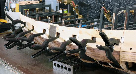
You can see in this photo that by not installing the guns and other items on the gun deck I was able to utilize the gun ports for clamping.

BP284.jpg
 
Next up it was time to do some planking. So I got my clamps out. Most people have seen this I would imagine but figured it wouldn’t hurt to show it. These clamps are just Binder clips from the office supply store. You can take the handles off of one and place it I another clip to make a planking clamp.

View attachment 183401

In the photo below you can see how the binder clips work.

View attachment 183402

The instructions are really ambiguous about how many planks to put where. I spent a lot of time going back and forth through the photos in the manual trying to figure out how many of what type of planks went where. I can’t say I really figured it out so much as I just developed a strategy and went for it. I was working on the starboard on the front and back and the stern on the port side lower deck area all at the same time. This allowed me to work continuously by going from one area to the next.

View attachment 183403

View attachment 183404

You can see in this photo that by not installing the guns and other items on the gun deck I was able to utilize the gun ports for clamping.

View attachment 183405
I tried the binder clip thing when I was doing the planking’ on my Black Pearl. Didn’t seem to hold the planking down as firmly as I would have liked so I ended up using push pins. How did yours work out?
 
The paulowina in particular in my kit was easy to bend once it was wet, my planks were probably within 1/16th of an inch of laying flat without anything holding them down. So the binder clips don't need to hold real strongly. If the wood was dry you're correct that they wouldn't hold.

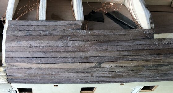
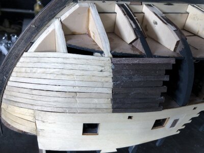
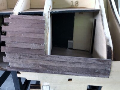
There are only 7 in place at this point but I ended up placing 10 full walnut planks across the area shown in the manual on the port side. I stained the planks with the black stain on the inside because these form the back wall of the lower deck. The instructions say the walnut planks are 450mm. I don’t know if that is the cut length or what. Mine were actually 500mm long so they were all cut down, but I didn’t measure the length I just cut them to fit from bulkhead center to bulkhead center where shown in the pictures in the manual.

BP285.jpg

On aft portion of the lower deck there is a pretty significant gap so I placed 4 planks across the bottom (top in the photo) below. I was a little concerned I might need some of the walnut strips later so didn’t want to use too much excess.

BP287.jpg

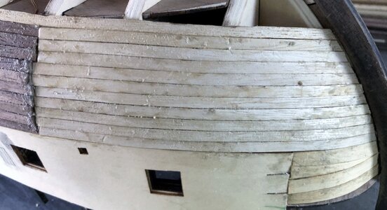
I ended up placing 11 paulowina strips and 10 walnut strips on the starboard bow area. This should get me to the level to run a plank along the lower deck. I trimmed the paulownia plank to match the walnut plank on the bottom.

BP288.jpg

On the port side I then placed 10 pieces to match the walnut planking and an eleventh that goes back to the first short walnut plank, to match the distance planked on the starboard side.

BP286.jpg

On the starboard aft section I placed the upper 4 walnut strips as shown in the photos. Then placed 8 offset length planks under those 4. I’m pretty sure the instructions show putting a wedge shaped plank between the planks in the photo and the one running the length of the deck. So that is my plan when I do the next section down.

BP289.jpg
 
Last edited:
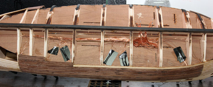
I mentioned when I posted the lantern build that I had ordered some extra magnet wire. The reason is because I’m concerned I used too much on some of the lower deck lanterns and don’t have enough for the captain’s cabin and lanterns on the back of the ship. The wire is scheduled to be here in a couple days so not a big problem. However; rite now I have to be careful not to close the bottom up to the point I can’t get the wires for the upper decks through.

I also wanted to mention the relatively obvious note that it doesn’t make a ton of difference if this first layer of planking is pretty because it’ll be covered by the second layer. Though, with that being said the plans show kind of an odd planking method of laying a plank in the middle of the bottom and then scab in a bunch of wedges on each side”. I haven’t decided the best way to approach it but I’m inclined to think I should just continue going down toward the keel and scab it in along the keel. I’ll think some more on that and let you know what I decide.

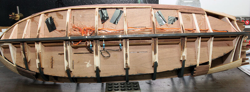
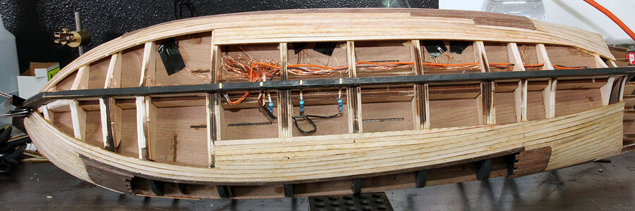
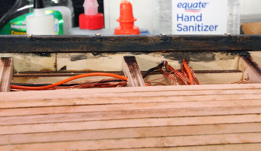
So at this point I decided it was time to figure out what to do with the rats nest of wires under the ship. I spent a significant amount of time studying how the electronics setup was intended to work. From that I decided it would probably be best to cross the wires to the opposite side of the ship to hook them up. In the photo below you can see I soldered the groups of wires into bundles that are sorted by deck so there is a positive and negative bundle for the lower deck and one for the gun deck in the photo below.

BP-290.jpg

Just a note about electronics. When I was in the US Navy they had a catchy phrase to remember all kinds of electronic stuff. For anodes and cathodes the saying is ”Don’t PANIC”. Positive is Anode Negative Is Cathode. The manual uses anode and cathode instead of positive and negative.

Oh! they had one for resistor color codes too!!! “Bad Boys Rap……” oops I’ll have to find a civilian version for that one. :D

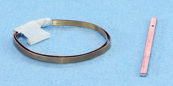
So Next I set off through the boxes in search of several parts. First was the copper strips that the instructions call out being attached to the keel for electric pickup. After some fairly extensive searching I decided the rolled up brass strip in the photo below must be what they really mean. I’ve noted several places where the manual incorrectly identifies what I believe to be brass as copper. The item beside the roll of brass is a strip of copper clad circuit board. I’ll explain what I’m going to do with that later it’s not part of the kit.

BP-291.jpg

While doing this I was going back and forth through the manual and it occurred to me that I had taken note of circuit board that they show being mounted inside the coffin, but I never saw one. I spent quite a bit of time looking for the circuit board before I noticed a little picture in the manual that shows the circuit board with a white chunk of plastic beside it. That’s when the bell finally went off, and I realized the circuit board is the end of the little cable with the writing on it in the photo below. The cable below needs to be unwrapped and modified which I’ll get to when the time comes. Also there are spring loaded pins that stick out of the top of the coffin and touch the contacts on the keel. That is how the light system is intended to work with the remote control.

BP-292.jpg

So now I had a grip on how this was designed to work. I’m not convinced this is a great idea and I have no idea why it was designed this way. But I decided it should work so I don’t know that I necessarily have a better way, just different ones.

This finally brings me back to what I was working on in the first place which was not closing up the bottom of the hull to early.

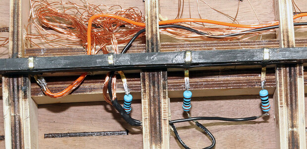
The instruction have you attach all of the positive wires to a brass strip toward the front of the ship, then has you create 3 more strips equally distanced and attach a 330 ohm resistor and then the negative side of each deck to a separate contact and resistor.

BP-293.jpg

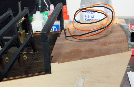
At this point I still had not installed the nine leds that go on the main deck (captains cabin / Lanterns) on back. I still hadn’t gotten the extra wire I ordered. So I thought about it a little and it occurred to me that there really isn’t and need to have 18 wires running beside each other all the way from the back of the ship to the connection point on the bottom, and then connect together. So I got out some 20 guage wire and just ran two wires one positive and one negative to the Captains cabin. That is what I got out the Copper clad strip for. I’m going to attach all of the lights in the captains cabin area to the copper strips and all of it will be powered by the pair of 20 guage wires. Orang and black ones in the photo. I’m pretty paranoid about doing my own wiring design without running all the numbers, but in this case all of the leds eventually get hooked to a single 28 gauge wire inside the coffin, and if that works the 20 gauge wires will be far more than adequate. Here’s a closer view of how I wired it up.

BP-294.jpg

Note in the photo above that I had a little trouble with getting a good bond between the brass and the keel so I took a thin strip of the walnut planking and glued a piece on each side of the keel to hold the brass strips in place. By staining it black it blends to where I don't expect people will notice it.
BP-295.jpg
Here’s where the wires come up into the captains cabin.
 
You’re doing great, Jodie! I got frustrated with soldering the tiny leds and ordered some already made. Would a 3 volt 1 amp adapter/transformer work instead of the 12 volt with resistors? That way I could solder all the positives to just one lead coming from the adapter. And the negatives to the other wire.
I also stained the buckets and barrels with black stain. I wanted it to be random and inconsistent so instead of painting it on, I just put a little bit in a plastic bag rolled the stuff around in it.

View attachment 182208

And here’s the results

View attachment 182209

So I spent quite a few days thinking on how to decorate the canon. Being as I’m going with the weathered look for the whole build I decided to try a faded red with patina on the barrel. I used Tamiya acrylic Nato Black paint on the barrel. Then the green patina is just weathering powder.

I made a wash of dark red paint about 80% water and 20 percent paint and then dipped the carriage in it.

View attachment 182210

And the final result

View attachment 182211

I will add more detail before I mount the canon this was just to figure the process out. I then did 18 more canon that way.

View attachment 182212

At this point I stopped and got the manual out. I do this periodically to figure out what I have done or missed etc. As I’ve mentioned before the photos in the manual at times seem to be kind of all over the place. Technically I’m at step 135 in the manual. This is one of those better have everything the way you want it before you go forward steps. It’s putting the Main deck in.

Now I know I’m not really ready because I haven’t put much of anything on the gun deck. So according to the instructions I skipped the following steps.

97 & 98 which is the 2 hammocks in the instructions. Not sure I want to do those at all but didn’t see a need to do them that early.

109 which is barrels and boxes that I didn’t want to put in until the guns are in place.

110-111 I really did this but didn’t cross it off because it’s the bow where I cut the wood off and I still need to build some filler blocks.

And last Step 120 which is the canons, canon balls etc..

So I have everything together to decorate the gun deck with the exception of ropes to hold the canons and any other minor details I want to put on this level.
Are you going to put straps on to attach cannon to carriage? What about rigging the cannon?
 
I don't know the answer to the transformer question. I don't have enough info on the provided leds to know. That is a question for the Evans people.

I haven't decided how detailed I'm going to get with the guns. I am planning on doing the big rope, probably not the blocks etc. Definitely not doing the blocks on the front being as there's nothing to attach them too. On the back they wouldn't probably be seen. That decision will likely be based on if I'm happy with the looks of the rest of the stuff, before I get to the guns. If it looks to bare to me I'll add more stuff.

So once the electric was ironed out, it was back to work on planking the hull, working from where I was toward the keel.

BP-297.jpg

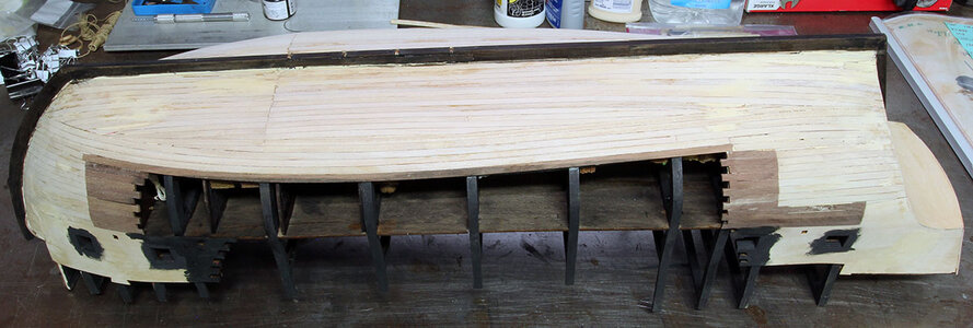
The sides of the ship are not even on one side vs the other. The reason for this is the planking on the port side starts at the bottom of the 1mm thick skin at under the gun deck and the starboard side starts under the cutout of the lower deck. This doesn’t really matter being as this won’t show when it’s finished.

I started working toward the center cutting diagonals on the end of the planks to go from the arch of the existing planking to the straight line of the keel.

BP-298.jpg

BP-299.jpg

Here’s a close view of the wood strips I glued on to secure the brass contacts. I was a little concerned that the strips might get broken loose and it would be really hard to fix after everything is planked.

BP-300.jpg

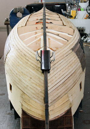
A view of the front at this point

BP-302.jpg

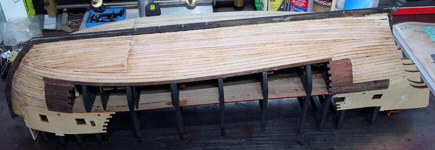
I wanted to take a minute and talk about the provided wood. The walnut is typical walnut, but the Pualowina, whatever the proper spelling, is some strange stuff. Dry it’s really brittle. It kind of feels like styrofoam. Living in the desert southwest this stuff snaps like Styrofoam when it’s dry. However it’s like a sponge and 15 minutes in water makes it nice to work with. Leave it in an hour and it’s down rite bendy. I had seen several people that complained about their wood being junk and just breaking so my assumption at this point is they didn’t soak the wood. Where there wasn’t a radical bend, I didn’t use a lot of clamps, I mostly was able to bend the wood to shapes close enough that a couple minutes held in place did the trick.

It took me about 16 hours to do all of the planking to get to the point below.

BP-306.jpg

BP-307.jpg

BP-308.jpg
 
Good looking job on this "pirated, pirated" model.

Very brave of you to take on this build. At $88.00, I would expect lots of missing pieces and incorrect measurements.

Looks like gluing everything down on the lower deck is required as I see you have turned the ship upside down to work on the hull.

I see the bow planking does not quite have the same curve as the deck.
Are planning on sanding that area off or filling it in?
 
This isn't the "pirated" "pirated" version. There are lot of Black Pearl threads it's easy to get them mixxed up. I do have the junk version but never tried to build it. Here's the log for the "pirated" "pirated" version. I also have a really tiny one that has tons of photoetch and resin cast figurehead and statues etc that might actually be buildable. It's overall length is about 14 inches. I may try to build it eventually.

This is the $600 ZHL version (with shipping) it's about three times the size of the cheap knockoff.

You could probably leave most of the boxes and stuff out and put them in after it's finished, but it would make it really difficult. The gun deck would be extremely challenging but could be done I would imagine. Even with this huge model there is still only about 2 inches between decks. I was a little concerned about all the dust from sanding the hull, but I just used my air compressor to blow it out after sanding and it looks fine.

On the planking it'll be a little of both. I added some filler in the next step, and then there is another layer of planking so when that is on it'll be closer to matching the outer line of the deck. Once that is on I'll sand the edge of the deck down to match the planking.
It seems different to use two different kinds of wood for the first layer of planking the hull.
 
It is weird, but makes sense the walnut is seen on the inside of the ship so it's necessary, but the paulowina is much easier to bend, so you don't have to fight the thick walnut around the curves.

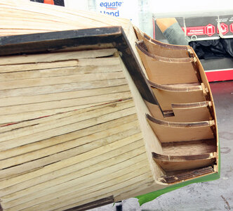
Next I turned my attention to the stern. I’d really like to get this planked to the point I can mount it on a stand. In order to do that, I needed to assemble part of the stern. Once again I ended up paging back and forth through the manual trying to figure out if it would cause any problems to assemble these parts. I didn’t see anywhere it would cause a problem so I went ahead with the assembly below.

I glued up the lower walls of the cabin and sanded the back to an angle.

BP-310.jpg

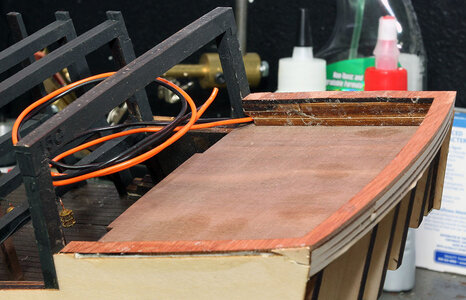
Then glued that part into the top. You can see in this photo that I sanded a notch in the bottom for the wires from down below.

BP-311.jpg

Next I glued on the aft piece. I did it by first gluing the top to the back of the wall piece in the photo above. I let that dry to align the top portion with the back of the captain’s cabin. After that was dry I pulled the sides up to match the existing side and used frog tape to hold the sides in place. The instructions tell you, you’ll have to fill in behind the stringers with scrap wood to make the back solid. I’m pretty sure there is a little more arch than intended in this piece but I’ve learned in the past that trying to force the plywood into a shape rarely ends well. So I just filled it with scrap as the instructions tell you too.

BP-312.jpg

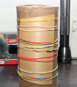
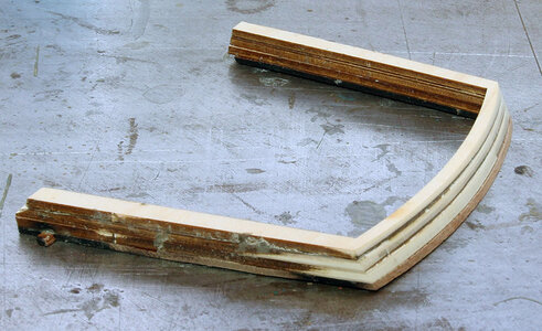
Next I soaked the plywood piece that goes below the last piece for about 2 hours in water, and then used rubber bands to hold it around a 3” diameter mailing tube. I let it dry overnight and the curvature was nearly perfect.

BP-313.jpg

In the photo below you can see I was just a little off on all sides. I actually feel like this is a pretty good fit for this type of construction.

BP-314.jpg
 
This isn't the "pirated" "pirated" version. There are lot of Black Pearl threads it's easy to get them mixxed up. I do have the junk version but never tried to build it. Here's the log for the "pirated" "pirated" version. I also have a really tiny one that has tons of photoetch and resin cast figurehead and statues etc that might actually be buildable. It's overall length is about 14 inches. I may try to build it eventually.

This is the $600 ZHL version (with shipping) it's about three times the size of the cheap knockoff.

You could probably leave most of the boxes and stuff out and put them in after it's finished, but it would make it really difficult. The gun deck would be extremely challenging but could be done I would imagine. Even with this huge model there is still only about 2 inches between decks. I was a little concerned about all the dust from sanding the hull, but I just used my air compressor to blow it out after sanding and it looks fine.

On the planking it'll be a little of both. I added some filler in the next step, and then there is another layer of planking so when that is on it'll be closer to matching the outer line of the deck. Once that is on I'll sand the edge of the deck down to match the planking.

I've been reading to many Black Pearl build logs !

Looks like I did get your build log confused with the other build log (pirated), apologies. Redface

That curved stern turned out nice.
 
Nice work Jodie. You are progressing at a rate of knots!
Heinrich - Funny you should mention that rite now. I'm actually just catching this log up with where I really am in the building process. Things will slow down some now. Particularly with the other projects I'm working on. However I do have an update tonight.

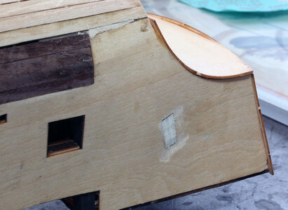
Next I used the elmers wood putty and did a bunch of sanding.

BP-315.jpg

BP-316.jpg

BP-317.jpg

BP-318.jpg

BP-319.jpg

And once the sanding was completed I went back and painted the gun ports black so the light wood doesn’t show around the edges by the final planking, and re-stained the keel. Etc. I also did some general touchup in preparation for the next layer of planking. I considered staining the whole thing so it any shows through it would be black but then decided I just need to do a better job than that on the final layer of planking. Here's after all the preparation.

BP-320.jpgBP-321.jpg
 
Last edited:
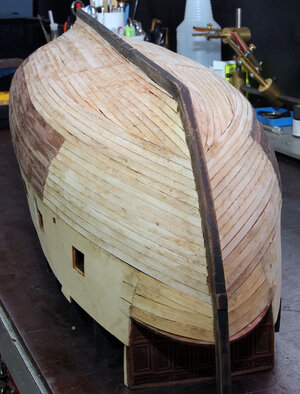
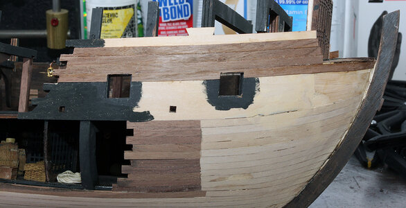
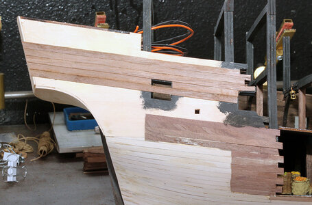
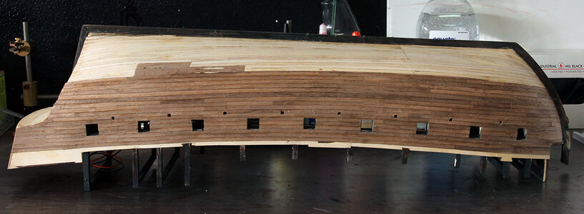
So next I started on the outer layer of planking. After examining the photos in the manual I decided the best way to locate the planking would be to use the top of the plywood sides, and then going down the width of 1 plank. I did that because there are a couple notches where the upper plywood skins are keyed into the lower plywood that is already on the model. I planked from that point down into the gun ports and then cut the top of the gun ports out. This gave me a start on where the gun ports are.

EDIT: If you're building this ship you might want to jump ahead and read post #130. The location of the whale that runs along the main deck can be just above what is planked below or 2 planks up from the walnut plank below. This has a lot of effect on the open side of the ship. It isn't a major problem either way but this would be a good time to look at where you want to place the whale. If you are going to use the lower location you may want to add a plank on the open side of the ship.

BP-322.jpg

BP-323.jpg

Then started planking on down

BP-324.jpg

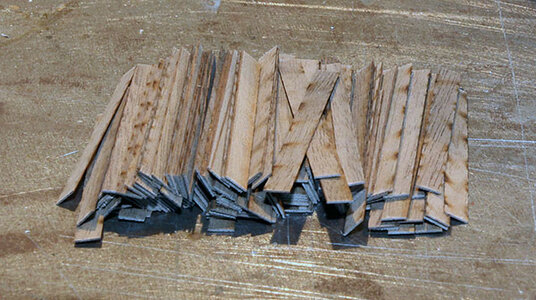
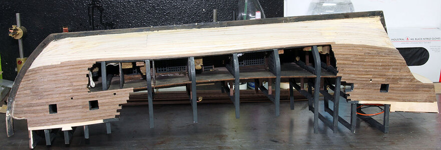
At his point the bend of the planks was getting fairly radical and the planks wanted to lift up off the hull on one side. I decided instead of fighting the way the planks wanted to twist up, I’d just plank shorter sections. So I cut 24 strips into pieces about 2.1 inches long. This is the longest distance between the gun ports.

BP-327.jpg

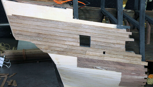
I planked down just into where the sweep ports are and then cut out the lower portion of the gun ports and the upper portion of the sweep ports. The farthest forward sweep ports were just barely into the planking but it was enough to locate them for trimming later.

BP-325.jpg

BP-326.jpg

Then put on a couple more planking runs and after it dried I cut the sweep ports the rest of the way out. When I got the sweep ports cut out I was cleaning the bench and holding the ship in one hand. This was when It slipped and I pretty much threw the ship halfway across the garage landing on the rear of the keel and then flipping over and slamming the front into the concrete.

I was afraid this may be the end of my Black Pearl build; however upon further examination. While the keel and the top of the stem obviously needed some repair work, beyond that the only damage was knocking one of the metal grates out.

So a half hour later I had the keel and stem glued back on and the metal bars back in. One final thing was to check the leds, and they all still light up. So everything turned out okay. You can see where I glued the stem back together and added a chunk of wood in the photo below.

BP-328.jpg

BP-329.jpg

BP-330.jpg

Reminded me of when I was in the Navy. When they build a new class of ship they do a shock test by taking the ship out in the ocean and setting of a large explosion in the water near it to see what flies off the wall. So the shock test has been completed no need to throw it down on the concrete again.

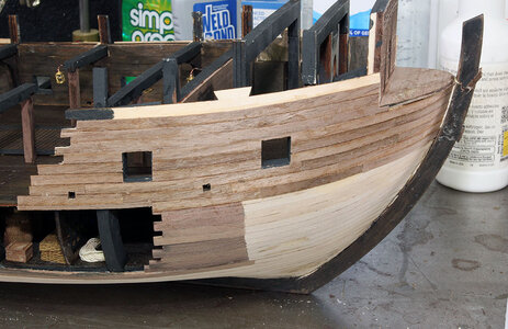
On the port side I planked down a couple more rows and then started just using the short pieces on the bow and longer ones toward the stern. Here’s where I stopped yesterday.

BP-331.jpg
 
Last edited:
You have done very well, Jodie. Just be careful that there aren't any more "shock tests"!:eek:
 
So next I started on the outer layer of planking. After examining the photos in the manual I decided the best way to locate the planking would be to use the top of the plywood sides, and then going down the width of 1 plank. I did that because there are a couple notches where the upper plywood skins are keyed into the lower plywood that is already on the model. I planked from that point down into the gun ports and then cut the top of the gun ports out. This gave me a start on where the gun ports are.

View attachment 185037

View attachment 185038

Then started planking on down

View attachment 185039

At his point the bend of the planks was getting fairly radical and the planks wanted to lift up off the hull on one side. I decided instead of fighting the way the planks wanted to twist up, I’d just plank shorter sections. So I cut 24 strips into pieces about 2.1 inches long. This is the longest distance between the gun ports.

View attachment 185040

I planked down just into where the sweep ports are and then cut out the lower portion of the gun ports and the upper portion of the sweep ports. The farthest forward sweep ports were just barely into the planking but it was enough to locate them for trimming later.

View attachment 185041

View attachment 185042

Then put on a couple more planking runs and after it dried I cut the sweep ports the rest of the way out. When I got the sweep ports cut out I was cleaning the bench and holding the ship in one hand. This was when It slipped and I pretty much threw the ship halfway across the garage landing on the rear of the keel and then flipping over and slamming the front into the concrete.

I was afraid this may be the end of my Black Pearl build; however upon further examination. While the keel and the top of the stem obviously needed some repair work, beyond that the only damage was knocking one of the metal grates out.

So a half hour later I had the keel and stem glued back on and the metal bars back in. One final thing was to check the leds, and they all still light up. So everything turned out okay. You can see where I glued the stem back together and added a chunk of wood in the photo above.

View attachment 185043

View attachment 185044

View attachment 185045

Reminded me of when I was in the Navy. When they build a new class of ship they do a shock test by taking the ship out in the ocean and setting of a large explosion in the water near it to see what flies off the wall. So the shock test has been completed no need to throw it down on the concrete again.

On the port side I planked down a couple more rows and then started just using the short pieces on the bow and longer ones toward the stern. Here’s where I stopped yesterday.

View attachment 185046
You’re taking “shiver me timbers” quite literally. Is that why you didn’t have guns installed on the gun deck already? Precognition?
 
You’re taking “shiver me timbers” quite literally. Is that why you didn’t have guns installed on the gun deck already? Precognition?
Yep, see beginning of post 53. I discussed that I was going to deviate from the plans because I thought the canons etc. would be in the way. I'm convinced that was a good decision at this point.


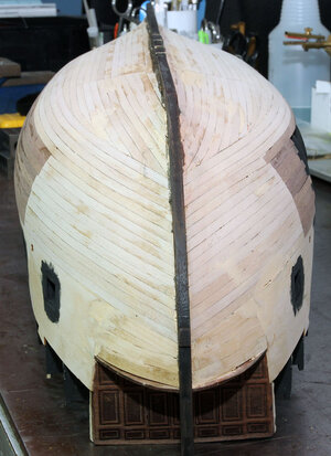
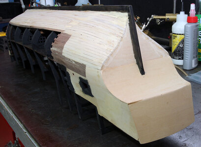
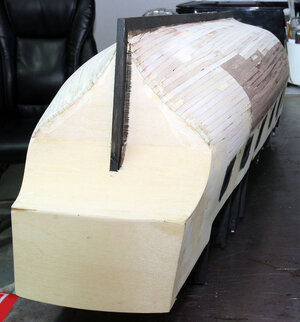
I haven’t posted in a while. The reason is I’ve been planking and the photos would be really boring if I posted one every few planks. I managed to get the port side finished to the bottom of the hull.

BP-334.jpg

I then planked on the starboard side down to where the full length starts as well. This isn’t fun or exciting IMO but I have to get through it to get to the next step.

BP-335.jpg

And finally just a few minutes ago I got the starboard side planked down to the keel.

BP-336.jpg

Obviously need to clean it up and sand, also need to figure out how much of the black to do. However; I think it might just have to wait for till after a fishing trip at this point.
 
Last edited:
I made it back from the fishing trip, and it snowed 7 inches so it's time to do a little modeling.

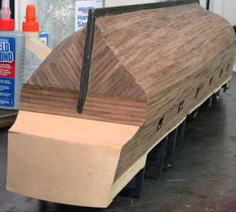
I spent quite a bit of time looking through the manuals again and you're never told to plank the stern anywhere in the manual. There is one photo near the end of the second part manual where you can see the planking on the lower portion of the stern. ZHL has the planking running parallel to the deck all the way to the bottom. I decided to plank the lower portion on an angle just because I like the look better. So here is what I did.

BP337.jpg

I planked the lower angled section first so the upper could be planked over the ends on the angled section. Next I placed the single long plank and made sure it was parallel with the bottom of the plywood that was exposed above the angled planks. I did this because I was concerned that if I started at the bottom, when I got to the single long plank the two outer planks below it wouldn't be in a straight line.

I still need to trim the ends of the planks I installed tonight, so it looks kind of strange. Hopefully I can finish planking up to the level of the sides tomorrow night.
 
Last edited:
Back
Top