Le Coureur 1776, CAF model 1:48 by Poul

Well we will know more when you find out how well it holds together.
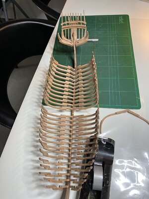
Hehe :D Since my question here did not reveal the answer I made my own investigation by means of a highly scientific method. My hypothesis was based on logical reasoning rather than IRL experience so as you say, it got to be tested. Hence I made a lot of experiments (read: 2) gluing 2 pieces of 2 mm wide sticks into a cross, clamping for 20 minutes, waiting 24 hours and then, by applying a steadily increasing force with my fingers perpendicular to one of the list with the center of the cross as fulcrum, I tried to assess how many Newton-metre it took to brake the cross apart. In one of the 2 experiment the sticks were threated with sanding sealer and in the other they were not. Thus by empirical observations I can conclude that my hypothesis was wrong :oops: Subsequently I have sanded it all back.

The lesson is: One thing is to understand a nautical chart, another is to sail a ship ;)
 
Last edited:
Hi Poul.
I have no experience with cellulose finishing. If by any chance you have gluing problems (I hope not and I think not) you could use the UhU Hart glue, which has always been used by model makers and which is precisely based on cellulose
I leave the wood unfinished until I end using the glue.
Then I use cooked linseed oil, an oil that has always been used for finishing wood because it mineralizes quickly and leaves the wood with a "lively" and natural appearance, while protecting it and giving it a light warm tone that is well suited to our wood models ( in my humble opinion).
Alternatively you can use Tung oil (an oil taken from a walnut-like plant that grows in China) or Danish oil, which is a mix of the two
 
As I said, I have kinda big hands and I found the space inside the building berth extremely tight. I got really annoyed having to use tweezers for everything so I have decided to build the whole ship outside the berth:
IMG_1015.JPG
Nah, I'm kidding :p. Even though I found it perfectly okay when I tested it during dryfit I realized anyway - after I had glued 90% of the frames to the keel - that some of those frames sitting on the top of the vertical walls was a little high compared to their neighbours. Hence, I took it all out of the berth and sanded away the steps on the vertical walls and put it all back in the berth again. Took a while to move every single frame one by one in small steps, a fraction of a inch at a time.
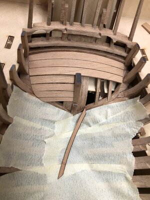
 
As I said, I have kinda big hands and I found the space inside the building berth extremely tight. I got really annoyed having to use tweezers for everything so I have decided to build the whole ship outside the berth:
View attachment 195732
Nah, I'm kidding :p. Even though I found it perfectly okay when I tested it during dryfit I realized anyway - after I had glued 90% of the frames to the keel - that some of those frames sitting on the top of the vertical walls was a little high compared to their neighbours. Hence, I took it all out of the berth and sanded away the steps on the vertical walls and put it all back in the berth again. Took a while to move every single frame one by one in small steps, a fraction of a inch at a time.
you are a brave man
 
I would like to share a small enhancement to this hint of Uwe's:
"PS: a small tip,: after two times a small piece was falling between the frames inside the jig, I covered the gaps between the frames with some masking tape, so that the pieces can not be lost in the "nirvana" of the jig - it is not so easy to get them out"
IMG-4891.jpg
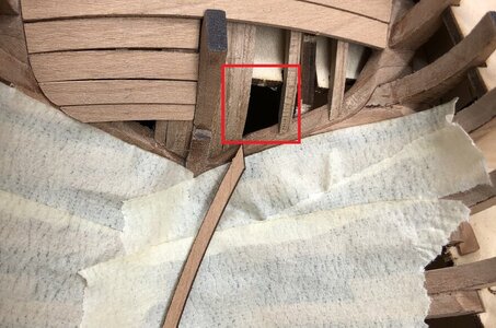
While it is true that it is not so easy to get parts out from under the frames there do exist places that are much worse. I have seen some pretty tight restrictions in cave systems in the Yucatan Peninsula but nothing compared to this one:
IMG-4891b.jpg

One of my ship builders who tried to cary frame 40 all by himself accidently stumbled and somehow both he and frame 40 dropped down that restriction into the cave below. Did I mention that I have big hands? I immediatelyy called in a SAR team but even for those guys a rescue attempt through the restriction failed.

In the end we had to dig a tunnel from the outside into the cave:
IMG_1019.JPG
Thus I'd suggest to cover also these restrictions (for as long as possible) :)

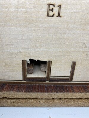
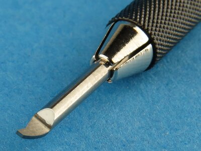
BTW, I have also slightly modified another of Uwe's tricks. Some weeks ago I visited a model shop in Denmark to buy some brass blackening. While I was there I also put a few other small items in the shopping basket, a couple of paintbrushes, a few scalpel blades and a small 0.3 mm engraving blade. I have absolutely no idea why I bought the engraving blade. Somehow it went into the shopping basket totally impulsive. There was no price tack on it but I reckoned the price would be around 1$.

I have been suffering severely from posttraumatic stress disorder ever since I got the bill. I paid 430 DKK for this tiny blade. It makes me so depressed thinking that I could have bought more than 150 bottles of good Carlsberg beer instead. I did not even have a clue what it could be used for. But now I have at least found some use for it: Uwe told that he is using a small chisel to remove the char between the frame futtocs. Did I mention that I have big hands? My chisels are also big so I tried this engraving blade instead and it actually works pretty good.
image006.jpg
 
very nice!
well done Poul
I would like to share a small enhancement to this hint of Uwe's:
"PS: a small tip,: after two times a small piece was falling between the frames inside the jig, I covered the gaps between the frames with some masking tape, so that the pieces can not be lost in the "nirvana" of the jig - it is not so easy to get them out"
View attachment 195908
While it is true that it is not so easy to get parts out from under the frames there do exist places that are much worse. I have seen some pretty tight restrictions in cave systems in the Yucatan Peninsula but nothing compared to this one:
View attachment 195911

One of my ship builders who tried to cary frame 40 all by himself accidently stumbled and somehow both he and frame 40 dropped down that restriction into the cave below. Did I mention that I have big hands? I immediatelyy called in a SAR team but even for those guys a rescue attempt through the restriction failed.

In the end we had to dig a tunnel from the outside into the cave:
View attachment 195913
Thus I'd suggest to cover also these restrictions (for as long as possible) :)

BTW, I have also slightly modified another of Uwe's tricks. Some weeks ago I visited a model shop in Denmark to buy some brass blackening. While I was there I also put a few other small items in the shopping basket, a couple of paintbrushes, a few scalpel blades and a small 0.3 mm engraving blade. I have absolutely no idea why I bought the engraving blade. Somehow it went into the shopping basket totally impulsive. There was no price tack on it but I reckoned the price would be around 1$.

I have been suffering severely from posttraumatic stress disorder ever since I got the bill. I paid 430 DKK for this tiny blade. It makes me so depressed thinking that I could have bought more than 150 bottles of good Carlsberg beer instead. I did not even have a clue what it could be used for. But now I have at least found some use for it: Uwe told that he is using a small chisel to remove the char between the frame futtocs. Did I mention that I have big hands? My chisels are also big so I tried this engraving blade instead and it actually works pretty good.
View attachment 195914
Hey Poul if you ever change your mind about the Carlsberg, gimme a shout and I’ll come over to help you. What are friends for
 
You had me for a minute. I was debating about whether to try and talk you back into using the jig :)

I did not fit the ends of the jig on, which makes things much easier. Mine arrived late and don't fit anyway due to deformation of the aft port side. Everything seems to be fitting well and decently symmetrical (off by 1/16" max) so I'm glad they aren't attached.
 
I would like to share a small enhancement to this hint of Uwe's:
"PS: a small tip,: after two times a small piece was falling between the frames inside the jig, I covered the gaps between the frames with some masking tape, so that the pieces can not be lost in the "nirvana" of the jig - it is not so easy to get them out"
View attachment 195908
While it is true that it is not so easy to get parts out from under the frames there do exist places that are much worse. I have seen some pretty tight restrictions in cave systems in the Yucatan Peninsula but nothing compared to this one:
View attachment 195911

One of my ship builders who tried to cary frame 40 all by himself accidently stumbled and somehow both he and frame 40 dropped down that restriction into the cave below. Did I mention that I have big hands? I immediatelyy called in a SAR team but even for those guys a rescue attempt through the restriction failed.

In the end we had to dig a tunnel from the outside into the cave:
View attachment 195913
Thus I'd suggest to cover also these restrictions (for as long as possible) :)

BTW, I have also slightly modified another of Uwe's tricks. Some weeks ago I visited a model shop in Denmark to buy some brass blackening. While I was there I also put a few other small items in the shopping basket, a couple of paintbrushes, a few scalpel blades and a small 0.3 mm engraving blade. I have absolutely no idea why I bought the engraving blade. Somehow it went into the shopping basket totally impulsive. There was no price tack on it but I reckoned the price would be around 1$.

I have been suffering severely from posttraumatic stress disorder ever since I got the bill. I paid 430 DKK for this tiny blade. It makes me so depressed thinking that I could have bought more than 150 bottles of good Carlsberg beer instead. I did not even have a clue what it could be used for. But now I have at least found some use for it: Uwe told that he is using a small chisel to remove the char between the frame futtocs. Did I mention that I have big hands? My chisels are also big so I tried this engraving blade instead and it actually works pretty good.
View attachment 195914
Great details of your "experience" with the cave and the "did I mention, that I have big hands......" - lol lol lol
Many Thanks - you made my day today :D
 
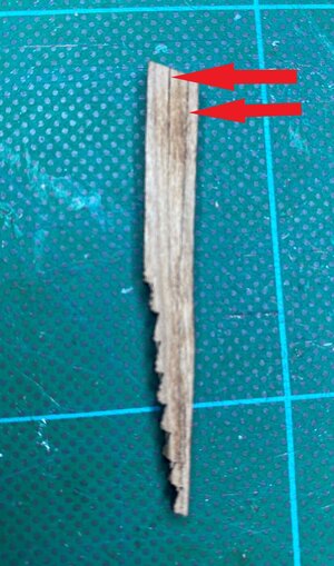
I need help again from fellow builders of Le Coureur. I'm puzzled about the beveling /fairing of cant frame 1. Unfortunately the back side of both of these pieces seemed to have catched a little fire or something so it was not possible to see the laserline. After some sanding I can climpse a line but there seems to be 2 lines (maybe even 3). Can that be right?
IMG_1025.JPG

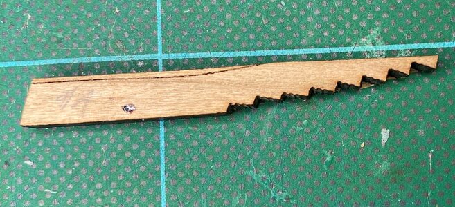
Looking at the front side I'm getting even more confused. If I bevel the upper half of the front side according to the line it will create an opening at both sides of the stem facing forward. That doesn't make sense to me. I'm thinking: Can it be that CAF, for reasons unclear to me, has reversed these 2 parts so that the front side is actually the back side? I'm thinking that maybe the beveling of the upper half could be to accomodate the deck clamps?
IMG_1027.JPG
 
I need help again from fellow builders of Le Coureur. I'm puzzled about the beveling /fairing of cant frame 1. Unfortunately the back side of both of these pieces seemed to have catched a little fire or something so it was not possible to see the laserline. After some sanding I can climpse a line but there seems to be 2 lines (maybe even 3). Can that be right?
View attachment 196430

Looking at the front side I'm getting even more confused. If I bevel the upper half of the front side according to the line it will create an opening at both sides of the stem facing forward. That doesn't make sense to me. I'm thinking: Can it be that CAF, for reasons unclear to me, has reversed these 2 parts so that the front side is actually the back side? I'm thinking that maybe the beveling of the upper half could be to accomodate the deck clamps?
View attachment 196436
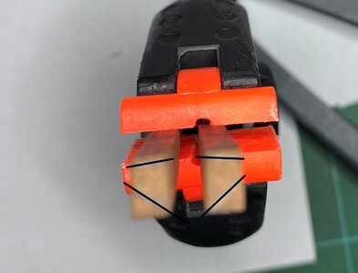
Hi Poul, we are all equally confused and that’s probably why no one has done frame one yet if I’m not mistaken
 
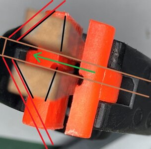
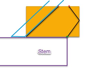
I think maybe I got it now, by looking at cut outs in the building berth. I think as follow: These frames should be canted 90 degrees so that what I called the "front side" is facing the stem and the step on the frames are facing direcly foward. There should actually be 2 lines on the "back side" (at least above deck) and above deck it should be faired/beveled aprox. as the black lines here:
IMG_1028.JPG
Unfortunately I cannot see the lines below deck.
Also I don't think this looks much like the picture of Tom's bow
 
Last edited:
Hallo my friends,
I had the same problem until now, after a first look at the parts - I did not understand the fairing lines, so I decided for me, that I will install them at the time starting with the outside hull planking - I think before it is not necessary to install them.
Good that you started now to discussion about these parts - very good, that several modelers are thinking about how to read it

Very good find with the photo @PoulD - for better visibility I resized your photo to see it better
3cropped.jpg

May I interpret your idea Poul in this way?

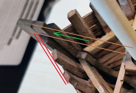
I turned your photo that it is appr. the same like the CAF photo - the black lines are yours, the brown would be the keel, the red the planking fixed on frame #1 - the green arrow would be the direction to the bow, so direction fore
IMG_1028.JPG

the same lines on the CAF photo
3croppeda.jpg

looking good - I have to take once more the wooden piece in hand - I will do this in the evening, when I am back in workshop

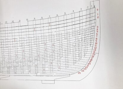
Important will be also this drawing, showing the frames from the side
IMG-4947.jpg
 
Mnjah. . . but I'm in some doubt if my idea can be correct. For 2 reasons:
a) the fairing against the inside planking of the bulwark would be the wrong way so to say
b) it would not look much like Tom's bow

I would much appreciate if one of you guys would post a good picture of the laser lines on the "back side" since the laser lines are very unclear on mine + there are some lines I thinks is caused either by natural coloration / cracks or damages in the wood
 
Last edited:
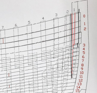
Many thank you Uwe. Your picture convinced me that my idea is correct. The laser marking fits exactly the red line on the drawing
1606902617003.png

Also I think the angle of the outer planking against the stem is better than it looks on the picture of Tom's build.
The only thing that still bothers me is the fairing against the inside planking of the bulwark
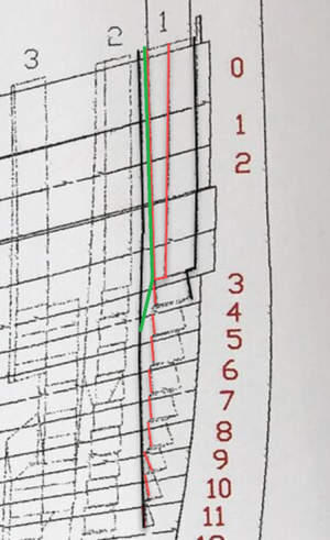
 
Many thank you Uwe. Your picture convinced me that my idea is correct. The laser marking fits exactly the red line on the drawing
View attachment 196561

Also I think the angle of the outer planking against the stem is better than it looks on the picture of Tom's build.
The only thing that still bothers me is the fairing against the inside planking of the bulwark
Yes - you are right -the other side would also fit - it would be the green line, or?
1606902617003.png
 
Back
Top