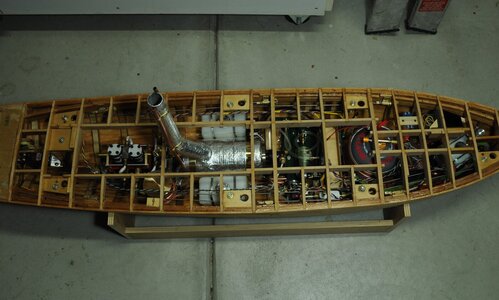
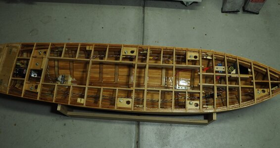
Working Steam powered wooden Drifter trawler, Formidable LT100, 1:24th scale

This is absolutely astounding work, I'm at a loss for words, there is no way that I could build a set up like that, not even in the next life with an engineering certificate under my belt, congrats and I long to see her on the water, I'm really enjoying your build Steve,

best regards John,
 
This is absolutely astounding work, I'm at a loss for words, there is no way that I could build a set up like that, not even in the next life with an engineering certificate under my belt, congrats and I long to see her on the water, I'm really enjoying your build Steve,

best regards John,
Thanks John,
I am really happy you are enjoying the build. I need to temper my desire to put her in the water, I need to plank the deck and make the bulwarks first.

Cheers,
Stephen.
 
Thanks a lot for explanation Steve. Now I remember having read the story about problems with your steam engine and fabrication of feedwater pump, but had completely forgotten that (age matters).
Very clever idea the two cylinder feedwater pump and an electric motor to drive it. But the control software behind is what interests me a lot.
During my working years I used to be involved with control configuration of power plants, and a couple of times I was also part of engineers planning the control systems for big power plants utilising once-through boilers. I remember the control philosophy was very complicated including many flow, pressure and temperature measurements, enthalpy calculations etc. The main criteria for controlling the block was the electrical output of generator, from where setpoints for all other control loops were generated. Also the control of boiler utilized steam flow to turbine and not constant steam pressure as conventional boilers.
I understand that with this kind of small scale it is not possible to use same sort of control philosophy than with full size plants, but it would be very interesting to see how you have combined together the steam and combustion gas flow controls.

No problem Moxis I have the same problem. :)

The theory behind a twin cylinder pump is to have a close to continuous feed, that is a feed without large pulses.
The sort of control you have experience with is well beyond my range.
At present there is no feed back, the system being controlled by mixing outputs on my radio this is for me to learn about how the system behaves before adding more complexity.
I intend to add at least one temperature sensor to monitor steam temperature, this will hopefully give me an idea of what is happening. The radio I use has telemetry and is easy to have 2 temperature sensors along with a flow meter, although I will keep it as simple as possible.
I will be happy if the plant runs reliably even if it is not the most efficient, as a power station would be.

Cheers,
Stephen.
 
Part 18.

Testing of steam plant!!

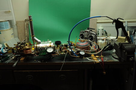
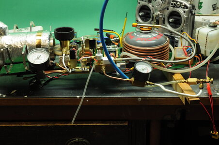
I started testing and rectifying problems and it still continues, both my feed pumps decided they didn't want to work after sitting for quite a while, I discovered that both of the inlet check valves (3mm balls) were sticking / jamming in their housings so I changed them to 1/8" balls problem fixed. Unfortunately it does my head in when I run into problems, in my head it should just work!!!

This is something that is improving as I get older, I am now less likely to throw my hands in the air so to speak.

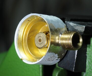
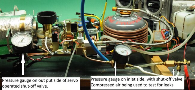
Then on testing for gas leaks using compressed air I found that the gas regulator I bought didn't have the output fitting soldered on properly and was leaking quite a bit.
DSC_0874 (2).JPGDSC_0878.JPGDSC_0880.JPG

I have now soft soldered the leak.
DSC_0880 (2).JPGDSC_0880 (4).jpg

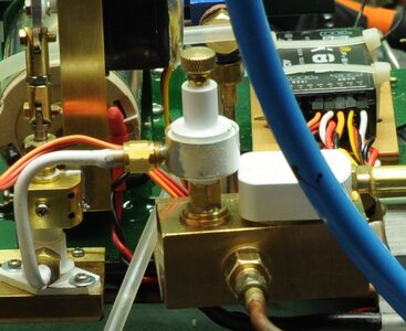
Then the output from my gas shutoff valve would not seal and after many headaches later I made a new output fitting machined off most of the old on then soft soldered the new one on problem fixed, looks like the guy in quality inspection was asleep on the job.

As testing progressed the gas metering and shutoff valve's work a treat. I didn't find out there was a problem with the gas shutoff output until I lit the burner and after a minute I had flames where I didn't want flames. This was quite alarming though all was under control after flicking the switch on the transmitter that closes the shut off valve.

A few days later things didn't improve much when I tried to run the steam plant (I went out with the expectation everything would work, this being the main problem) and nothing seemed to work apart from feed pumps and gas valves that is.

I tried lighting the new burner that was now in it’s correct place for the first time and it would not run when inside the generator ( I have probably made the flue diameter too small, I did think of a temporary fan to induce a draft through the generator, though I didn’t try it ) when I got it to run by removing the bush that centralises it in the generator it didn't seem to do much. Not happy!!!

I went inside for a while to settle down and start to think about what had happened.

I thought I would try the old Cheddar steam burner ( I had made up pipe work to try it anyway) what a difference things started to happen, I discovered that I had filled the entire system with water including the engine which I think sort of hydraulic’ed and locked up I had hot water coming out all over the place and not much else happening.

I was ready to give the whole thing up and either buy a commercial steam engine or just put an electric motor in and be done with it. To say I felt dejected would be an understatement. I went back inside again. I even had a look at a beautiful Martin Baylis Engineering twin slide valve engine, I hate to think how much one of those is….

Once I started to rationalise the whole thing I started to calm down, I decided that next morning I would run the engine on compressed air first to prove that it would run.

So next morning I hooked compressed air up to my engine and it ran, I found that the main leaks were from the forward/reverse valve, I removed it then pulled it apart flattened both faces reassembled and ran with compressed air, the engine seemed to run well.

I changed the feed pump curve on the transmitter and halving the feed pump max speed to reduce water flow.

I tried running the plant again and to my joy it ran, still pumping too much water though. It has run several times now still reducing the amount of feed water.

There is still more to do on the plant, like adding temperature sensors to monitor steam temperature and maybe ambient inside temperature.

Here are a couple of short videos showing running the plant, I hope the links work.


Thanks for looking in comments/questions are welcome and Happy New Year to all the crew at SOS.

Cheers,
Stephen.
 
Part 18.

Testing of steam plant!!

I started testing and rectifying problems and it still continues, both my feed pumps decided they didn't want to work after sitting for quite a while, I discovered that both of the inlet check valves (3mm balls) were sticking / jamming in their housings so I changed them to 1/8" balls problem fixed. Unfortunately it does my head in when I run into problems, in my head it should just work!!!

This is something that is improving as I get older, I am now less likely to throw my hands in the air so to speak.

Then on testing for gas leaks using compressed air I found that the gas regulator I bought didn't have the output fitting soldered on properly and was leaking quite a bit.
View attachment 203121View attachment 203122View attachment 203123

I have now soft soldered the leak.
View attachment 203124View attachment 203125

Then the output from my gas shutoff valve would not seal and after many headaches later I made a new output fitting machined off most of the old on then soft soldered the new one on problem fixed, looks like the guy in quality inspection was asleep on the job.

As testing progressed the gas metering and shutoff valve's work a treat. I didn't find out there was a problem with the gas shutoff output until I lit the burner and after a minute I had flames where I didn't want flames. This was quite alarming though all was under control after flicking the switch on the transmitter that closes the shut off valve.

A few days later things didn't improve much when I tried to run the steam plant (I went out with the expectation everything would work, this being the main problem) and nothing seemed to work apart from feed pumps and gas valves that is.

I tried lighting the new burner that was now in it’s correct place for the first time and it would not run when inside the generator ( I have probably made the flue diameter too small, I did think of a temporary fan to induce a draft through the generator, though I didn’t try it ) when I got it to run by removing the bush that centralises it in the generator it didn't seem to do much. Not happy!!!

I went inside for a while to settle down and start to think about what had happened.

I thought I would try the old Cheddar steam burner ( I had made up pipe work to try it anyway) what a difference things started to happen, I discovered that I had filled the entire system with water including the engine which I think sort of hydraulic’ed and locked up I had hot water coming out all over the place and not much else happening.

I was ready to give the whole thing up and either buy a commercial steam engine or just put an electric motor in and be done with it. To say I felt dejected would be an understatement. I went back inside again. I even had a look at a beautiful Martin Baylis Engineering twin slide valve engine, I hate to think how much one of those is….

Once I started to rationalise the whole thing I started to calm down, I decided that next morning I would run the engine on compressed air first to prove that it would run.

So next morning I hooked compressed air up to my engine and it ran, I found that the main leaks were from the forward/reverse valve, I removed it then pulled it apart flattened both faces reassembled and ran with compressed air, the engine seemed to run well.

I changed the feed pump curve on the transmitter and halving the feed pump max speed to reduce water flow.

I tried running the plant again and to my joy it ran, still pumping too much water though. It has run several times now still reducing the amount of feed water.

There is still more to do on the plant, like adding temperature sensors to monitor steam temperature and maybe ambient inside temperature.

Here are a couple of short videos showing running the plant, I hope the links work.


Thanks for looking in comments/questions are welcome and Happy New Year to all the crew at SOS.

Cheers,
Stephen.
Your determination not to give up was rewarded in this trial run after so many problems before. What are the steps to get it into the trawler for a launching? Outstanding!!! Rich (PT-2)
 
Your determination not to give up was rewarded in this trial run after so many problems before. What are the steps to get it into the trawler for a launching? Outstanding!!! Rich (PT-2)

Yes Rich they say persistence pays of.
The plant is able to be put into the hull at any time and is held in place by 3 custom made screws.
As for getting her into the water I want to plank the deck and build the bulwarks then paint the hull and bulwarks in one go before her maiden voyage.
It is true that I could paint the lower hull and give her a run but I don't want to do it in that order.

Thanks for your comments.

Cheers,
Stephen.
Good for your choice of priorities. Sound planning. Rich
 
Part 19.

With things settling down in the engine room, and having run my plant several times without any real drama I started looking at what next.

Early in this project I decided that a forced ventilation system would be something I would try, seeing I don’t like the idea of letting convection move the hot air out of a fairly enclosed area.

To make this happen I wanted to fit a fan at either end of the boat with one in the bows pushing outside air in and the other pulling air out, or maybe pushing air in creating a combined flow up the funnel, ventilators and any other opening.

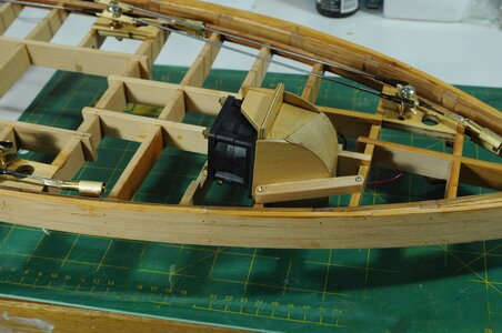
Luckily there is a hooded companionway in the bows under neath which I can hide a fan.

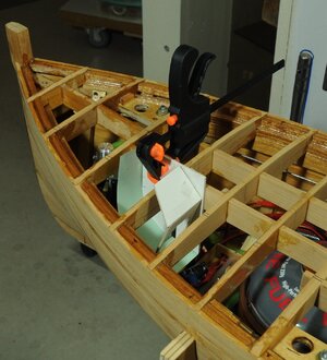
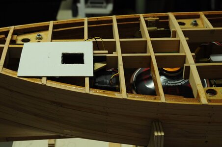
With the rail back in the hull, I worked out the fan’s location on the deck then made a card board representation of the companionway opening.

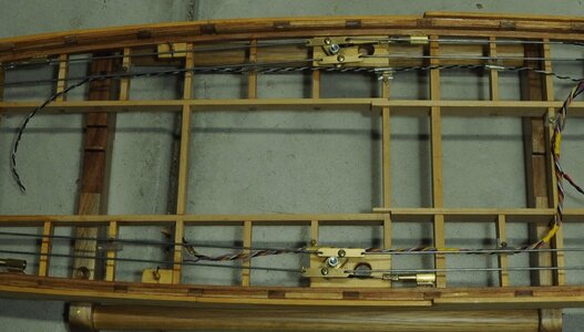
All of this work was made a lot easier due to there only being deck beams, therefore I could clearly see where things could go.

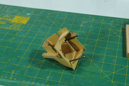
A cardboard mock up was made of the duct that would connect the fan to the deck beams.
DSC_0887 (2).JPG

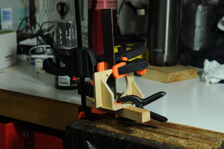
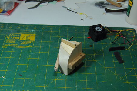
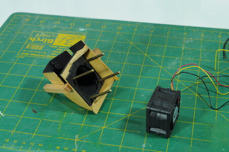
Then once the shape was settled these shapes were transferred to ply wood cut out and glued together. The whole assembly including fan is easily removable.
DSC_0889.JPGDSC_0896.JPGDSC_0906.JPG

Inside duct painted black and foam added to help with vibration isolation of the fan.
DSC_0908.JPGDSC_0913s.jpgDSC_0916.JPGDSC_0917s.jpg

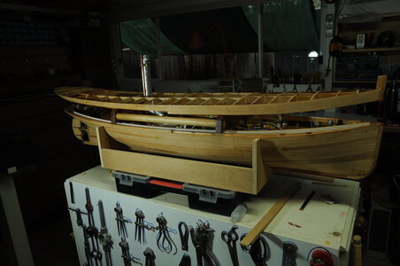
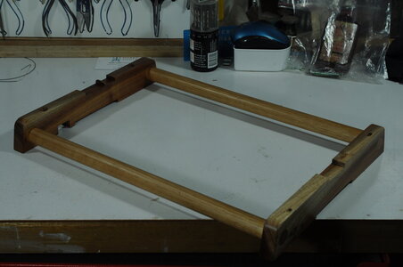
I then made a stand to sit the rail on when out of the model, while designing this I decided to make it multi purpose, one other use being to keep the lower hull and upper hull separated for unplugging a multi pin plug another use being to display the model.
DSC_0903.JPGDSC_0901.JPGDSC_0898.JPG

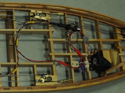
In the removable deck section there is a bit of wiring that in my opinion needed to be done now while there is easy vision and access. Wiring is needed for lighting, power to a voltage multiplier to run the 2 fans at up to 24 volts, for 2 servos to control the mizzen sail one servo hopefully to raise and lower the other for sail trimming. All of this going through a multi pin plug, the plug I bought is only an audio plug but seeing that I think there will only be about 1 amp running through any one of the pins at any one time I think it should do the job.
DSC_0924 (2).JPGDSC_0924 (3).JPG

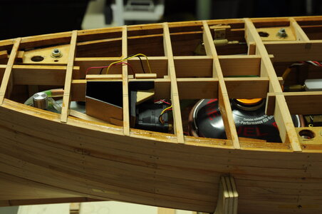
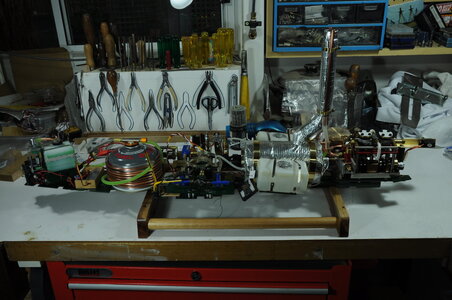
With the rail in there is not a lot of room for much else, funny how it has filled up with equipment considering I thought there was plenty of room in the beginning.
DSC_0925 (2).JPGDSC_0926 (2).JPG

If you have any questions don’t hesitate to ask.

Thanks for looking in.

Cheers,
Stephen.
 
Part 18.

Testing of steam plant!!

I started testing and rectifying problems and it still continues, both my feed pumps decided they didn't want to work after sitting for quite a while, I discovered that both of the inlet check valves (3mm balls) were sticking / jamming in their housings so I changed them to 1/8" balls problem fixed. Unfortunately it does my head in when I run into problems, in my head it should just work!!!

This is something that is improving as I get older, I am now less likely to throw my hands in the air so to speak.

Then on testing for gas leaks using compressed air I found that the gas regulator I bought didn't have the output fitting soldered on properly and was leaking quite a bit.
View attachment 203121View attachment 203122View attachment 203123

I have now soft soldered the leak.
View attachment 203124View attachment 203125

Then the output from my gas shutoff valve would not seal and after many headaches later I made a new output fitting machined off most of the old on then soft soldered the new one on problem fixed, looks like the guy in quality inspection was asleep on the job.

As testing progressed the gas metering and shutoff valve's work a treat. I didn't find out there was a problem with the gas shutoff output until I lit the burner and after a minute I had flames where I didn't want flames. This was quite alarming though all was under control after flicking the switch on the transmitter that closes the shut off valve.

A few days later things didn't improve much when I tried to run the steam plant (I went out with the expectation everything would work, this being the main problem) and nothing seemed to work apart from feed pumps and gas valves that is.

I tried lighting the new burner that was now in it’s correct place for the first time and it would not run when inside the generator ( I have probably made the flue diameter too small, I did think of a temporary fan to induce a draft through the generator, though I didn’t try it ) when I got it to run by removing the bush that centralises it in the generator it didn't seem to do much. Not happy!!!

I went inside for a while to settle down and start to think about what had happened.

I thought I would try the old Cheddar steam burner ( I had made up pipe work to try it anyway) what a difference things started to happen, I discovered that I had filled the entire system with water including the engine which I think sort of hydraulic’ed and locked up I had hot water coming out all over the place and not much else happening.

I was ready to give the whole thing up and either buy a commercial steam engine or just put an electric motor in and be done with it. To say I felt dejected would be an understatement. I went back inside again. I even had a look at a beautiful Martin Baylis Engineering twin slide valve engine, I hate to think how much one of those is….

Once I started to rationalise the whole thing I started to calm down, I decided that next morning I would run the engine on compressed air first to prove that it would run.

So next morning I hooked compressed air up to my engine and it ran, I found that the main leaks were from the forward/reverse valve, I removed it then pulled it apart flattened both faces reassembled and ran with compressed air, the engine seemed to run well.

I changed the feed pump curve on the transmitter and halving the feed pump max speed to reduce water flow.

I tried running the plant again and to my joy it ran, still pumping too much water though. It has run several times now still reducing the amount of feed water.

There is still more to do on the plant, like adding temperature sensors to monitor steam temperature and maybe ambient inside temperature.

Here are a couple of short videos showing running the plant, I hope the links work.


Thanks for looking in comments/questions are welcome and Happy New Year to all the crew at SOS.

Cheers,
Stephen.
Isn't it nice when it finally all comes together and runs!
Had all the same sorts of problems when I built 'Natterer' - you just had to step back, think your way through it, and sort them out, just as you have.
Great work!

Ted
 
Part 19.

With things settling down in the engine room, and having run my plant several times without any real drama I started looking at what next.

Early in this project I decided that a forced ventilation system would be something I would try, seeing I don’t like the idea of letting convection move the hot air out of a fairly enclosed area.

To make this happen I wanted to fit a fan at either end of the boat with one in the bows pushing outside air in and the other pulling air out, or maybe pushing air in creating a combined flow up the funnel, ventilators and any other opening.

Luckily there is a hooded companionway in the bows under neath which I can hide a fan.

With the rail back in the hull, I worked out the fan’s location on the deck then made a card board representation of the companionway opening.

All of this work was made a lot easier due to there only being deck beams, therefore I could clearly see where things could go.

A cardboard mock up was made of the duct that would connect the fan to the deck beams.
View attachment 204282

Then once the shape was settled these shapes were transferred to ply wood cut out and glued together. The whole assembly including fan is easily removable.
View attachment 204283View attachment 204284View attachment 204285

Inside duct painted black and foam added to help with vibration isolation of the fan.
View attachment 204286View attachment 204287View attachment 204288View attachment 204289

I then made a stand to sit the rail on when out of the model, while designing this I decided to make it multi purpose, one other use being to keep the lower hull and upper hull separated for unplugging a multi pin plug another use being to display the model.
View attachment 204290View attachment 204291View attachment 204292

In the removable deck section there is a bit of wiring that in my opinion needed to be done now while there is easy vision and access. Wiring is needed for lighting, power to a voltage multiplier to run the 2 fans at up to 24 volts, for 2 servos to control the mizzen sail one servo hopefully to raise and lower the other for sail trimming. All of this going through a multi pin plug, the plug I bought is only an audio plug but seeing that I think there will only be about 1 amp running through any one of the pins at any one time I think it should do the job.
View attachment 204293View attachment 204294

With the rail in there is not a lot of room for much else, funny how it has filled up with equipment considering I thought there was plenty of room in the beginning.
View attachment 204295View attachment 204296

If you have any questions don’t hesitate to ask.

Thanks for looking in.

Cheers,
Stephen.
Good job there's plenty of space in that hull! - have you made the shoe-horn yet?
Lovely job

Ted
 
Part 19.

With things settling down in the engine room, and having run my plant several times without any real drama I started looking at what next.

Early in this project I decided that a forced ventilation system would be something I would try, seeing I don’t like the idea of letting convection move the hot air out of a fairly enclosed area.

To make this happen I wanted to fit a fan at either end of the boat with one in the bows pushing outside air in and the other pulling air out, or maybe pushing air in creating a combined flow up the funnel, ventilators and any other opening.

Luckily there is a hooded companionway in the bows under neath which I can hide a fan.

With the rail back in the hull, I worked out the fan’s location on the deck then made a card board representation of the companionway opening.

All of this work was made a lot easier due to there only being deck beams, therefore I could clearly see where things could go.

A cardboard mock up was made of the duct that would connect the fan to the deck beams.
View attachment 204282

Then once the shape was settled these shapes were transferred to ply wood cut out and glued together. The whole assembly including fan is easily removable.
View attachment 204283View attachment 204284View attachment 204285

Inside duct painted black and foam added to help with vibration isolation of the fan.
View attachment 204286View attachment 204287View attachment 204288View attachment 204289

I then made a stand to sit the rail on when out of the model, while designing this I decided to make it multi purpose, one other use being to keep the lower hull and upper hull separated for unplugging a multi pin plug another use being to display the model.
View attachment 204290View attachment 204291View attachment 204292

In the removable deck section there is a bit of wiring that in my opinion needed to be done now while there is easy vision and access. Wiring is needed for lighting, power to a voltage multiplier to run the 2 fans at up to 24 volts, for 2 servos to control the mizzen sail one servo hopefully to raise and lower the other for sail trimming. All of this going through a multi pin plug, the plug I bought is only an audio plug but seeing that I think there will only be about 1 amp running through any one of the pins at any one time I think it should do the job.
View attachment 204293View attachment 204294

With the rail in there is not a lot of room for much else, funny how it has filled up with equipment considering I thought there was plenty of room in the beginning.
View attachment 204295View attachment 204296

If you have any questions don’t hesitate to ask.

Thanks for looking in.

Cheers,
Stephen.
No questions. must amazement at the miracles that seem to come from your creative mind. Outstanding! Rich
 
Back
Top