Thanks Rich,
I do tend to have problems with complements, something I am trying to work on, I probably tend to under value my own work, ( something I think I inherited from my dad ).
Cheers,
Stephen.
Second thought related to compliments and respect which should never be demanded: we were taught how to be good loosers. . . but how often have you been advised how to be a good winner? (Without gloating, demeaning the loosing opponent, grand-standing, overly high-fiving, spiking the ball, etc. . . . ) I don't recall any of the coaches on my son or daughter's teams telling them how to win. That was something that we talked about more at home and not before others. RichThat is a beautifully executed row boat. Precise, symmetrical, and well detailed. Rich (PT-2)
-

Win a Free Custom Engraved Brass Coin!!!
As a way to introduce our brass coins to the community, we will raffle off a free coin during the month of August. Follow link ABOVE for instructions for entering.
-

PRE-ORDER SHIPS IN SCALE TODAY!
The beloved Ships in Scale Magazine is back and charting a new course for 2026!
Discover new skills, new techniques, and new inspirations in every issue.
NOTE THAT OUR FIRST ISSUE WILL BE JAN/FEB 2026
You are using an out of date browser. It may not display this or other websites correctly.
You should upgrade or use an alternative browser.
You should upgrade or use an alternative browser.
Working Steam powered wooden Drifter trawler, Formidable LT100, 1:24th scale
- Thread starter Stevedownunder
- Start date
- Watchers 33
Thanks Rich,That is a beautifully executed row boat. Precise, symmetrical, and well detailed. Rich (PT-2)
I am happy you like the work boat, somewhere in the future it will be weathered a bit.
Cheers,
Stephen.
Thanks Rich,That is a beautifully executed row boat. Precise, symmetrical, and well detailed. Rich (PT-2)
I am happy you like the work boat, somewhere in the future it will be weathered a bit.
Cheers,
Stephen.
Sorry about the double post, I am having some internet problems.
Cheers,
Stephen.
Cheers,
Stephen.
I thought that you may like to see a steam fired tug boat being fired up. Skip the ads. .. hope this link works:Sorry about the double post, I am having some internet problems.
Cheers,
Stephen.
https://youtu.be/dS-Q1DvvOeY
Rich
Thanks Rich,I thought that you may like to see a steam fired tug boat being fired up. Skip the ads. .. hope this link works:
https://youtu.be/dS-Q1DvvOeY
Rich
Great video, at 1/24th that tug would be 27" long.
Cheers,
Stephen.
TOOT! TOOT! Full steam ahead and here we go! Glad that you liked it with all of the steam engine details of which you are well familiar. I don't have any steam with Bluenose except what I try to control when I realize my last blunder. ;-( Rich (PT-2)Thanks Rich,
Great video, at 1/24th that tug would be 27" long.
Cheers,
Stephen.
I am busy in the engine room shovelling coal into the boiler and oiling the engine and doing 9 knots.TOOT! TOOT! Full steam ahead and here we go! Glad that you liked it with all of the steam engine details of which you are well familiar. I don't have any steam with Bluenose except what I try to control when I realize my last blunder. ;-( Rich (PT-2)
Don't reach too far in as the blower creates quite a draftI am busy in the engine room shovelling coal into the boiler and oiling the engine and doing 9 knots.

Part 17.
Back to the engineering side of things, next job was gas control.
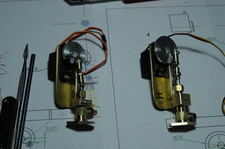
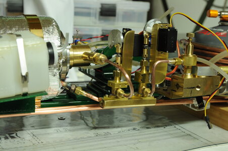
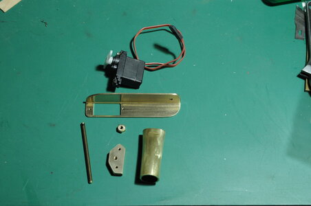
I had a look around the internet trying to get some design ideas for RC servo controlled gas metering valves to no avail, all I came up with were some commercially made RC servo controlled gas shut off valves. For one reason or another nothing suited my instillation, in the end I decided to make 2 externally similar valves and mount them on a manifold, similarly to how Hydraulic and Pneumatic valves are mounted in industrial installations. One reason for this was to reduce overall space taken.
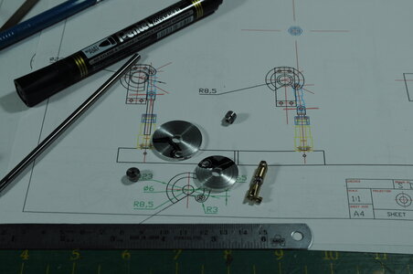
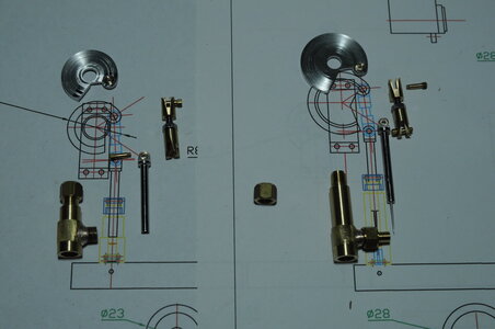
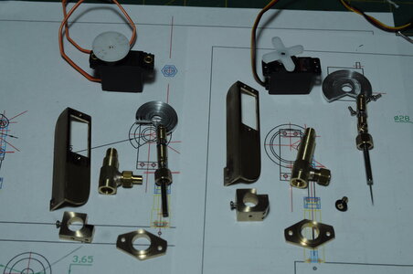
There are some things that I need to draw before attempting to make and these valves fall into this category. Using CAD I designed then built a metering / flow control valve and a shut off valve.
The metering valve allows me to go from an idle flame through to full flame.
I am also using a small commercial gas regulator this should give me a constant pressure and therefore a constant flame.
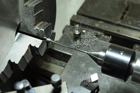
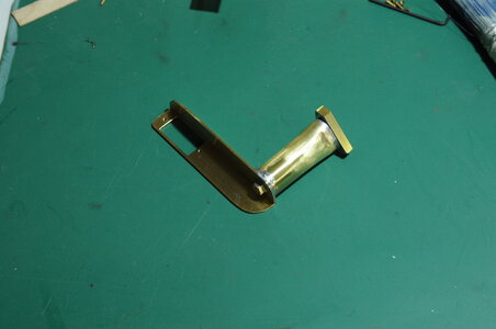
I started buy making the metering needle this was quite tricky, being made from Stainless Steel with a taper of around 2 degrees, this made for a taper length of around 15mm going from a point up to 1mm diameter add a polished finish and this took me around one day to do. In the end I rejected the first needle and proceeded making up the body linkage and servo horn adaptor.
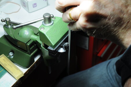
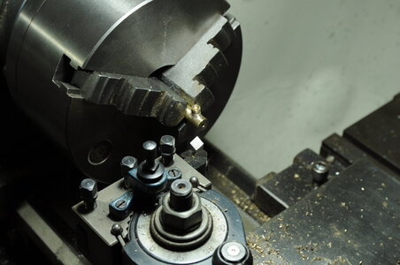
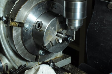
For the servo horn adaptor I machined a disk with a groove on the lathe, then in the mill I machined a notch finishing off with a file. The small radius was filed by hand up to a guide turned on the lathe, this made it really easy to achieve a nice radius.
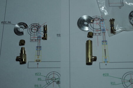
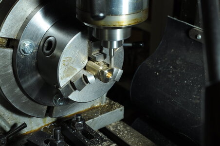
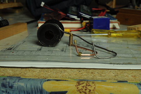
Two pipe’s were made one for each gas burner that I have, when I am making up odd shaped piping I use wire of some sort that is close to the same diameter as my pipe in this case I used heavy gauge soft solder bent to shape as a guide.
More photos in next post.
Back to the engineering side of things, next job was gas control.
I had a look around the internet trying to get some design ideas for RC servo controlled gas metering valves to no avail, all I came up with were some commercially made RC servo controlled gas shut off valves. For one reason or another nothing suited my instillation, in the end I decided to make 2 externally similar valves and mount them on a manifold, similarly to how Hydraulic and Pneumatic valves are mounted in industrial installations. One reason for this was to reduce overall space taken.
There are some things that I need to draw before attempting to make and these valves fall into this category. Using CAD I designed then built a metering / flow control valve and a shut off valve.
The metering valve allows me to go from an idle flame through to full flame.
I am also using a small commercial gas regulator this should give me a constant pressure and therefore a constant flame.
I started buy making the metering needle this was quite tricky, being made from Stainless Steel with a taper of around 2 degrees, this made for a taper length of around 15mm going from a point up to 1mm diameter add a polished finish and this took me around one day to do. In the end I rejected the first needle and proceeded making up the body linkage and servo horn adaptor.
For the servo horn adaptor I machined a disk with a groove on the lathe, then in the mill I machined a notch finishing off with a file. The small radius was filed by hand up to a guide turned on the lathe, this made it really easy to achieve a nice radius.


Two pipe’s were made one for each gas burner that I have, when I am making up odd shaped piping I use wire of some sort that is close to the same diameter as my pipe in this case I used heavy gauge soft solder bent to shape as a guide.

More photos in next post.
Last edited:
Part 17.2
More photos.
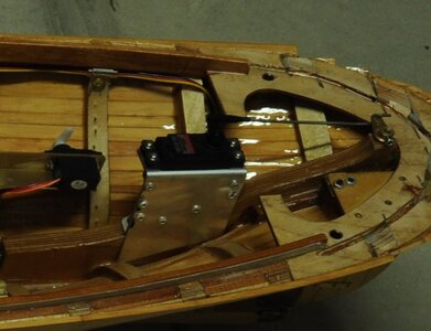
I also made up a servo mount for the forward/reverse and rudder servos along with 3 special long screws for holding down the plant rail, these screws enable installation and removal without tools also it is easier. Any non coloured Brass parts were given a coat of clear Lacquer.
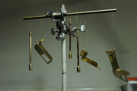
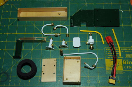
Painted parts ready for installing, including battery box, feed pump speed control box, multi plug battery lead and gas burner mounting ring. All gas equipment is painted white.
Rudder servo and link installed. Home made wire clamps keeping the wiring neat and tidy.
Next 3 photos are of the rail with most equipment installed.
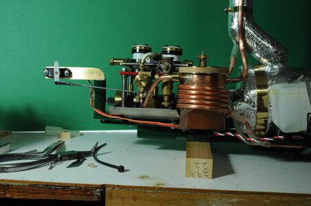
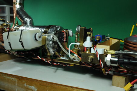
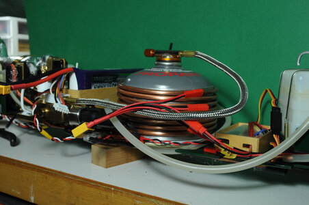
Control of the steam engine requires 3 servos, one for gas metering, one for feed pump speed, one for forward / reverse on the engine. All controlled from a single input on the transmitter, which is a Taranis 9XD+ programmed via OpenTX Companion.
A switch on the transmitter controls a forth servo for the gas on / off valve.
If you have any questions don’t hesitate to ask.
Thanks for having a look.
Cheers,
Stephen.
More photos.
I also made up a servo mount for the forward/reverse and rudder servos along with 3 special long screws for holding down the plant rail, these screws enable installation and removal without tools also it is easier. Any non coloured Brass parts were given a coat of clear Lacquer.


Painted parts ready for installing, including battery box, feed pump speed control box, multi plug battery lead and gas burner mounting ring. All gas equipment is painted white.

Rudder servo and link installed. Home made wire clamps keeping the wiring neat and tidy.

Next 3 photos are of the rail with most equipment installed.


Control of the steam engine requires 3 servos, one for gas metering, one for feed pump speed, one for forward / reverse on the engine. All controlled from a single input on the transmitter, which is a Taranis 9XD+ programmed via OpenTX Companion.
A switch on the transmitter controls a forth servo for the gas on / off valve.
If you have any questions don’t hesitate to ask.
Thanks for having a look.
Cheers,
Stephen.
Your engineering design ability and very small scale machining work absolutely amaze me by what you are producing in this working steam engine for the trawler. Outstandingly well done!!!! RichPart 17.2
More photos.
I also made up a servo mount for the forward/reverse and rudder servos along with 3 special long screws for holding down the plant rail, these screws enable installation and removal without tools also it is easier. Any non coloured Brass parts were given a coat of clear Lacquer.
View attachment 200071View attachment 200072View attachment 200073
Painted parts ready for installing, including battery box, feed pump speed control box, multi plug battery lead and gas burner mounting ring. All gas equipment is painted white.
View attachment 200074
Rudder servo and link installed. Home made wire clamps keeping the wiring neat and tidy.
View attachment 200075
Next 3 photos are of the rail with most equipment installed.
View attachment 200076View attachment 200077View attachment 200078
Control of the steam engine requires 3 servos, one for gas metering, one for feed pump speed, one for forward / reverse on the engine. All controlled from a single input on the transmitter, which is a Taranis 9XD+ programmed via OpenTX Companion.
A switch on the transmitter controls a forth servo for the gas on / off valve.
If you have any questions don’t hesitate to ask.
Thanks for having a look.
Cheers,
Stephen.
Thanks there Rich,
Cheers,
Stephen.
Cheers,
Stephen.
Thanks Jimsky,
I am very happy to hear that the "WOW" factor is evident, that is intentional to have some "bling" on the inside of my model.
Cheers,
Stephen.
I am very happy to hear that the "WOW" factor is evident, that is intentional to have some "bling" on the inside of my model.
Cheers,
Stephen.
Very nice engineering indeed Stephen. You are building a very unique steam engine plant which interests me a lot. Therefore a few questions:
- what kind of feedwater pump are you using? Does it have an own steam engine or an electric motor? How do you control feedwater flow? With flash boilers this might be the main subject for controlling.
- what kind of burners are you using? Are they your own fabrication or commercial products?
- how about the main steam engine to turn the propeller? Your own fabrication or commercial product?
- could you explain more why have you selected such a complicated shape for gas metering valve servo horn?
Very nice engineering indeed Stephen. You are building a very unique steam engine plant which interests me a lot. Therefore a few questions:
- what kind of feedwater pump are you using? Does it have an own steam engine or an electric motor? How do you control feedwater flow? With flash boilers this might be the main subject for controlling.
- what kind of burners are you using? Are they your own fabrication or commercial products?
- how about the main steam engine to turn the propeller? Your own fabrication or commercial product?
- could you explain more why have you selected such a complicated shape for gas metering valve servo horn?
Hi Moxis,
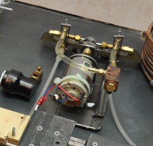
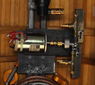
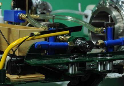
Thanks for your questions, I built a twin cylinder feed pump that is horizontally opposed driven by an electric motor. I go into more detail in part 14.
Here are some photos;
This photo is early showing the assembly removed from the rail, and plumbed up, including output manifold .
This photo is even earlier no plumbing, clearly showing the horizontally opposed layout.
All painted up and looking pretty.
Feed water flow is controlled by a speed controller. You are right feed water control along with burner control is what flash steam is largely about.
Both burners are commercial one is a now old Cheddar unit the other is a Microcosm steam burner.
The engine is all my own work to a Model Boats plan, there is more info in part 2 and 12.
I didn't think the servo horns were overly complex they just ended up that way while drawing them in CAD, one of my design considerations was to not have a twisting force applied to the servo horn therefore requiring a cut-out to clear the connecting link, I guess this cut-out made things a bit more complex. I wanted them to be robust and able to attach well to the original servo horn.
I hope this helps, if not let me know.
Cheers,
Stephen.
Thanks a lot for explanation Steve. Now I remember having read the story about problems with your steam engine and fabrication of feedwater pump, but had completely forgotten that (age matters).
Very clever idea the two cylinder feedwater pump and an electric motor to drive it. But the control software behind is what interests me a lot.
During my working years I used to be involved with control configuration of power plants, and a couple of times I was also part of engineers planning the control systems for big power plants utilising once-through boilers. I remember the control philosophy was very complicated including many flow, pressure and temperature measurements, enthalpy calculations etc. The main criteria for controlling the block was the electrical output of generator, from where setpoints for all other control loops were generated. Also the control of boiler utilized steam flow to turbine and not constant steam pressure as conventional boilers.
I understand that with this kind of small scale it is not possible to use same sort of control philosophy than with full size plants, but it would be very interesting to see how you have combined together the steam and combustion gas flow controls.


