HMS Sovereign of the Seas - Bashing DeAgostini Beyond Believable Boundaries

That is a most impressive ship Kurt - note - not model. Your dedication to doing things right is admirable and certainly an example to me as well.
There's a lot you can do with basic tools. I wish I could carve like Janos! The decorations for this build are going to be the greatest challenge.
 
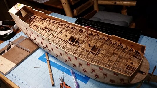
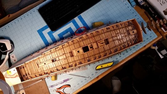
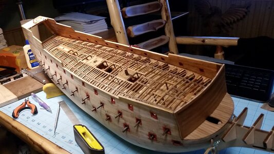
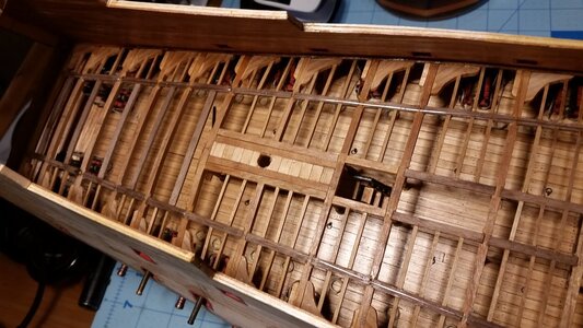
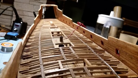
All the ledges for the upper gun deck are complete. Next comes the lighting. Wires will be routed along the tops of the beams and yellow nano-LED's installed as deck lanterns for the middle gun deck below.

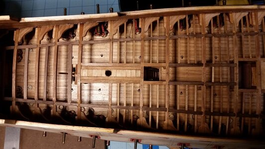
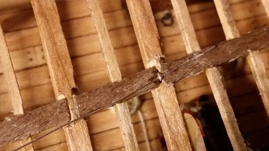
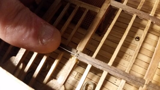
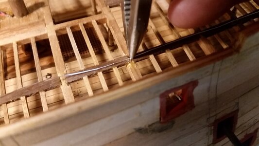
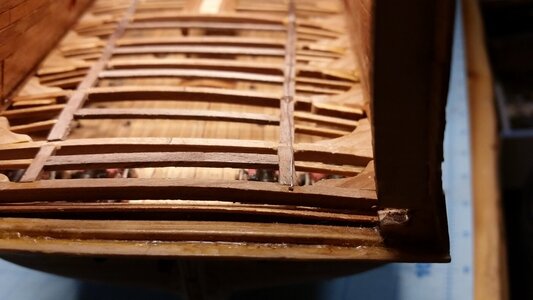
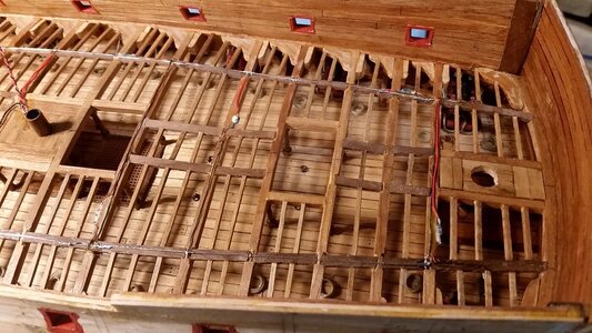
The last ledges are in place. It was tough getting the last ones deep in the stern castle and these took the longest time because access was cramped. A dental pick was used to adjust the ledges into final position and wipe off excess glue.
930 Install Last Ledges for Upper Gun Deck.jpg

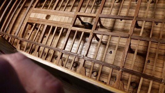
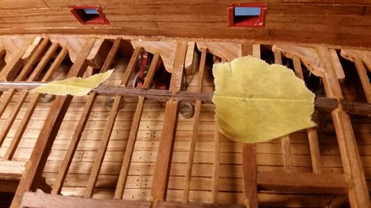
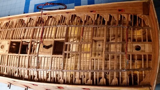
Top view showing all the details.
931 All Ledges Installed.jpg

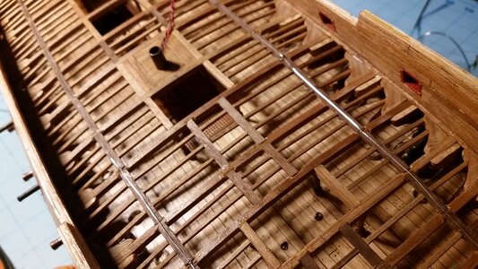
Ready for LED installation.
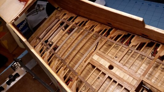
932 Progress So Far.jpg
 
All the ledges for the upper gun deck are complete. Next comes the lighting. Wires will be routed along the tops of the beams and yellow nano-LED's installed as deck lanterns for the middle gun deck below.

The last ledges are in place. It was tough getting the last ones deep in the stern castle and these took the longest time because access was cramped. A dental pick was used to adjust the ledges into final position and wipe off excess glue.
View attachment 314637

Top view showing all the details.
View attachment 314638

Ready for LED installation.
View attachment 314639
That's a fast moving build!
I'm more than curious about your led light installation, since I'm having difficulty installing led lights in my Bluenose build.
 
That's a fast moving build!
I'm more than curious about your led light installation, since I'm having difficulty installing led lights in my Bluenose build.
Watch the next few posts. I'm about to start the lighting for the middle gun deck. There are so many ways to do it, but I have a method that works with the tools I've got.

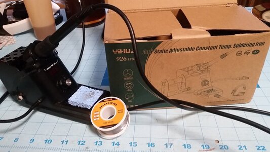
This is the inexpensive soldering iron and solder I will be using again on the lighting circuit. I found it on Amazon. There are many better and more expensive ones like it, but this one is mine. The solder that came with it was solid and melted at such a high temperature that I could not wet the tip of the iron, much less get it to flow and stick to any wires. I bought this soft, flux core solder, and all my problems went away. Soldering was as easy as writing with a pen.
933 Soldering Iron Used.jpg
 
Last edited:
A lot of LED's were installed today. I ran out of nano yellow LED's and had to order more from Evan's Designs in order to continue work, but this is how far I got. These tiny yellow LED's are a simple way of simulating lanterns hanging from the beams overhead.

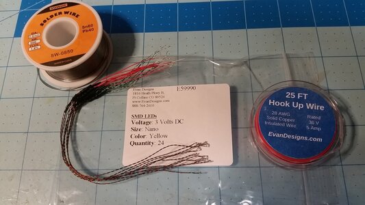
Here are the LED's, wire, and the solder that will be used. The LED's are only 1mm wide.
934 LED's Used.jpg

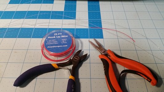
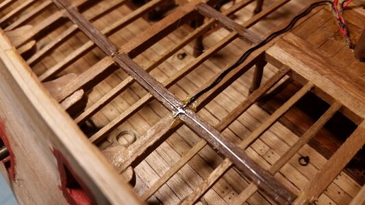
Two lengths of 24 gauge wire, each as long as the deck, are carefully stripped of insulation. These will be two long conductors running over the beams along the outboard carlings from bow to stern. The port side conductor will be positive, and the starboard one negative.
934 Srrip Insulation off 24 gage Wire.jpg

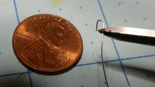
To hold the wire conductors to the beams, 24 gauge wire staples are made using a needle nose pliers.
936 Make Wire Staples.jpg

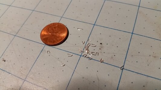
Here is a pile of staples ready for use.
937 Staples Made from 24g Wire.jpg

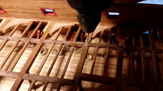
A tiny drill is used in a battery powered Dremel tool to drill two small holes for the staples in beams every 8 cm along the carling.
938 Drill Holes for Staples With Drfemel.jpg

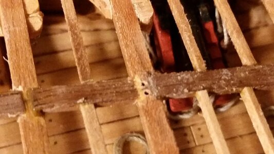
Holes for the staple.
939 Holes for Staple.jpg

Starting with the starboard (negative) conductor, the first staple is secured over the conductor near the bow with CA glue.
940 Glue Staple to Hold Conductor with CA Glue.jpg

The next staple is inserted and glued in place.
941 Insert Staples Every 8cm to Hold Conductors to Beams.jpg

Each staple must be held down until the CA glue cures.
942 Press Staple Until CA Glue Dries.jpg

Keep stapling the conductor every 8cm until you reach the end of the deck at the stern
943 Negative Conductor Wire on Stbd Side.jpg

The end of the conductor is secured simply by bending the end down and gluing it into a drilled hole at the stern.
944 End of Conductor Wire is Glued in Hole.jpg

Since the wires are springy and hard to manage, use masking tape to hold loose wire in position as you work. Here, masking tape is also used to hold a staple in place until the CA cures.
945 Masking Tape Used to Hold Conductors While Glue Dries.jpg

Here is a view of both conductors near the bow.
946 Repeat for Positive Conductor on Port Side.jpg

Conductors near the stern.
947 Conductors at Aft End.jpg

Overall view of the deck structure and the conductors in place.
948 Conductors on Forward Edn.jpg

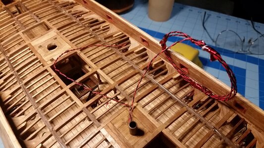
The two remaining circuit wires are separated. The one reserved for powering lights in the stern in coiled up and set aside. The wires for this deck's lights is trimmed and made ready to solder to the two conductors.
949 Separate Two Remaining Power Wires.jpg

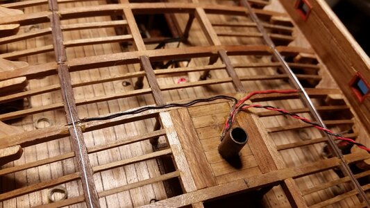
The positive and negative wires are routed the conductors, red to positive, black to negative, and trimmed to length. The bare ends of the wires are held down by the conductor wires.
950 Run Power Wires to Conductors.jpg

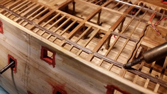
The power wires are soldered to the conductors.
951 Solder Power Wires to Conductors.jpg

Finished solder connection. The soft, flux core solder makes this very easy and quick.
952 Black Wire Soldered to Negative Conductor.jpg

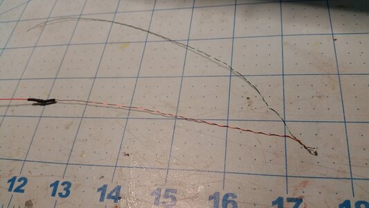
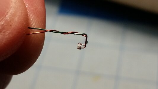
Each LED has a resistor on the positive lead, covered with shrink tube. The leads are untwisted, leaving 1cm of wire twisted just in front of the LED. If you untwist all the wire, one of the leads will break off the LED, ruining it. The shrink tube on the resistor will be removed using a razor knife, because in most cases, the resistor will have to be repositioned to some other location on the positive lead. This location is determined for each individual LED as you install them. The resistors are glued to the sides of the beams, because they are too thick to fit between the false deck and the beams later in the build. The wires are thin enough to fit between the false deck and beams without distorting the deck to any significant degree.
953 Untwist Yellow Nano LED Leads.jpg

Each LED will wrap around a beam or a ledge. To help hold them in place, they are hooked around the beam, and glued in place with the LED facing downward.
954 Form Leads to go Around Beam.jpg

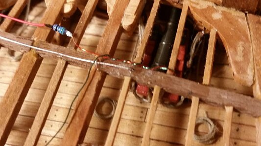
It's hard to see here, but the LED is wrapped around a ledge with a bit of glue holding it in place, and the positive lead and resistor are still loose. The negative (green) lead is routed to the other side of the ship toward the negative conductor. The LED is out of view, under the carling, and facing down to shine on the middle gun deck below.
955 LED Hooks Around Beam or Ledge.jpg

The first three LED's are installed. Each of the wires and resistors in held in place with spots of PVA glue, which appear invisible except for the wet glue covering the resistor from the center LED located one beam forward of the main hatchway, which appears yellow-white.
956 Route and Solder LED Leads to Conductors and Secure With PVA Glue.jpg

The first 8 LED's in the forward section of the ship are installed. All the wires on top of the beams were carefully straightened and tacked to the beams in several spots using PVA glue. The edges of the false deck sections will be positioned on either side of the wires wherever possible to reduce gaps between the false deck and the beams below to a minimum.
957 LED's Forward of Fore Capstan Installed.jpg

The AC transformer is plugged into an outlet, and the DC plug is plugged into the socket on the bottom of the model. The adjacent switch on the bottom of the hull is turned on, and the lights are tested. Success! Every light works. More LED's will be installed all the way to the stern when they arrive in the mail.
958 Test the LED's.jpg
 
A lot of LED's were installed today. I ran out of nano yellow LED's and had to order more from Evan's Designs in order to continue work, but this is how far I got. These tiny yellow LED's are a simple way of simulating lanterns hanging from the beams overhead.

Here are the LED's, wire, and the solder that will be used. The LED's are only 1mm wide.
View attachment 314827

Two lengths of 24 gauge wire, each as long as the deck, are carefully stripped of insulation. These will be two long conductors running over the beams along the outboard carlings from bow to stern. The port side conductor will be positive, and the starboard one negative.
View attachment 314828

To hold the wire conductors to the beams, 24 gauge wire staples are made using a needle nose pliers.
View attachment 314829

Here is a pile of staples ready for use.
View attachment 314830

A tiny drill is used in a battery powered Dremel tool to drill two small holes for the staples in beams every 8 cm along the carling.
View attachment 314831

Holes for the staple.
View attachment 314832

Starting with the starboard (negative) conductor, the first staple is secured over the conductor near the bow with CA glue.
View attachment 314833

The next staple is inserted and glued in place.
View attachment 314834

Each staple must be held down until the CA glue cures.
View attachment 314835

Keep stapling the conductor every 8cm until you reach the end of the deck at the stern
View attachment 314836

The end of the conductor is secured simply by bending the end down and gluing it into a drilled hole at the stern.
View attachment 314837

Since the wires are springy and hard to manage, use masking tape to hold loose wire in position as you work. Here, masking tape is also used to hold a staple in place until the CA cures.
View attachment 314838

Here is a view of both conductors near the bow.
View attachment 314839

Conductors near the stern.
View attachment 314840

Overall view of the deck structure and the conductors in place.
View attachment 314841

The two remaining circuit wires are separated. The one reserved for powering lights in the stern in coiled up and set aside. The wires for this deck's lights is trimmed and made ready to solder to the two conductors.
View attachment 314842

The positive and negative wires are routed the conductors, red to positive, black to negative, and trimmed to length. The bare ends of the wires are held down by the conductor wires.
View attachment 314843

The power wires are soldered to the conductors.
View attachment 314844

Finished solder connection. The soft, flux core solder makes this very easy and quick.
View attachment 314845

Each LED has a resistor on the positive lead, covered with shrink tube. The leads are untwisted, leaving 1cm of wire twisted just in front of the LED. If you untwist all the wire, one of the leads will break off the LED, ruining it. The shrink tube on the resistor will be removed using a razor knife, because in most cases, the resistor will have to be repositioned to some other location on the positive lead. This location is determined for each individual LED as you install them. The resistors are glued to the sides of the beams, because they are too thick to fit between the false deck and the beams later in the build. The wires are thin enough to fit between the false deck and beams without distorting the deck to any significant degree.
View attachment 314846

Each LED will wrap around a beam or a ledge. To help hold them in place, they are hooked around the beam, and glued in place with the LED facing downward.
View attachment 314847

It's hard to see here, but the LED is wrapped around a ledge with a bit of glue holding it in place, and the positive lead and resistor are still loose. The negative (green) lead is routed to the other side of the ship toward the negative conductor. The LED is out of view, under the carling, and facing down to shine on the middle gun deck below.
View attachment 314848

The first three LED's are installed. Each of the wires and resistors in held in place with spots of PVA glue, which appear invisible except for the wet glue covering the resistor from the center LED located one beam forward of the main hatchway, which appears yellow-white.
View attachment 314849

The first 8 LED's in the forward section of the ship are installed. All the wires on top of the beams were carefully straightened and tacked to the beams in several spots using PVA glue. The edges of the false deck sections will be positioned on either side of the wires wherever possible to reduce gaps between the false deck and the beams below to a minimum.
View attachment 314850

The AC transformer is plugged into an outlet, and the DC plug is plugged into the socket on the bottom of the model. The adjacent switch on the bottom of the hull is turned on, and the lights are tested. Success! Every light works. More LED's will be installed all the way to the stern when they arrive in the mail.
View attachment 314851
Very interesting way of doing it, Kurt. I'm curious, though, the person at Evans Design told me I wouldn't need resistors unless I went over 100 lights. I wonder if I understood her incorrectly. They were different LED lights, however.
 
Ingenious, Kurt, just ingenious.
Especially to run two conductors over the length of the ship and hooking up the leds left and right.
The repositioning of the resistors is something I'm struggling with; the leds + wiring come untwisted, meaning the connections to the led are suspect to breakage. I repositioned quite a few resistors, with almost as many leds broken off. Then I started removing the shrink sleeve from the resistor, coiled both wires to the length required and inserted the coiled wires plus resistors into a shrink sleeve. After that I hooked the leds up to the two wires from the power supply. Unfortunately that becomes quite bulky, whereas your approach apparently require little extra space.
Very nicely done!
 
Very interesting way of doing it, Kurt. I'm curious, though, the person at Evans Design told me I wouldn't need resistors unless I went over 100 lights. I wonder if I understood her incorrectly. They were different LED lights, however.
The 3V nano LED's I used have built in resistors soldered on the positive leads, and these are required when wiring them in parallel. All you need is a 3 volts DC for each LED, and you need not worry about burning them out. The resistance of the resistors has already been calculated and selected by Evan's Designs. Now, if you wire a bunch of them in series without any resistors in the circuit, the more LED's you have in the circuit, the dimmer they get. So, if you have one LED, it will be so bright and see such high current that it will have a short life, and burn out. LED's have very little resistance, and burn out early if there is excess current. But if you have a lot more in series, you can set the brightness by the number of LED's you have in that circuit. Each LED drops the current a tiny bit. I don't know how many you need in a series circuit until they are not burnt out by excess amperage, but if you have enough to dim the set of lights noticeably, you are probably in the safe range with regard to current. In most circuits, you need resistors, and there is a method of calculating the resistance required in order to avoid burning out the LED's.
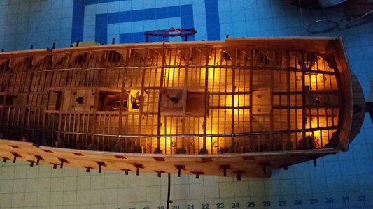
What you don't know, unless you followed my build closely, is that my LED's are very dim to simulate lanterns. This is because I added a second resistor, one for each of the three separate circuits I chose to make. These resistors were soldered to in the red and black power wires down in the hold of the ship model. I made a test circuit before doing any wiring in the model, and tested a circuit with varying resistors to get the level of illumination I wanted. I probably should have used larger resistor for each circuit in the hold, and eliminated the small resistors on each of the LED's, but I already had the LED's and went with what I had. That way, I would not have to struggle to find places for the small resistors between the ledges and beams of the deck structures.

They also sell 5V LED's. These require a different resistance to prevent burnout. The resistance offered by different size LED's is different, and the resistors you need to protect those from overcurrent are different. The fellows at Evan's Designs are VERY helpful at helping you choose the correct lights and setting up the correct circuit so your LED's will have maximum life, which is approximately 25 years of continuous light. They were very helpful when I had questions.
 
Last edited:
Ingenious, Kurt, just ingenious.
Especially to run two conductors over the length of the ship and hooking up the leds left and right.
The repositioning of the resistors is something I'm struggling with; the leds + wiring come untwisted, meaning the connections to the led are suspect to breakage. I repositioned quite a few resistors, with almost as many leds broken off. Then I started removing the shrink sleeve from the resistor, coiled both wires to the length required and inserted the coiled wires plus resistors into a shrink sleeve. After that I hooked the leds up to the two wires from the power supply. Unfortunately that becomes quite bulky, whereas your approach apparently require little extra space.
Very nicely done!
You have to be VERY careful with the LED's and their leads. I broke several myself. I used small needle nose plier to made the bends in the wires near the LED's precisely and carefully because the leads break off easily. That's why you want to leave the wires twisted near the LED's, because the connection to the LED are very brittle and weak. Careful planning of each LED and its leads helps prevent breakage. The use of two longitudinal conductors organizes what would be a maze of wire leads and simplifies the installation of the circuit immensely. It also lets you see the each LED in this parallel circuit, and plan where and how many leads have to travel across each beam so the wires do not get concentrated in one place, making it harder to create a level deck above the whole mess. The conductors don't need insulation, because you are making a low voltage circuit, so you won't have to worry about your ship bursting into flames if something shorts out. :D Of course, now that I think of it, HMS Sovereign of the Seas did end her days catching fire and burning to the waterline. Hmmm....

I bend the "C" shape in the wires near the LED first, test fit the LED on the beam, measure where I want to relocated the resistor, so it ends up alongside a beam between carlings, cut the read lead to length, then take the LED back out of the model for more prep work.

To clean the insulation off the leads, you scrape the wiring with the edge of a razor knife all around the wire to expose fresh copper. The resistor in soldered to a new location on the positive lead, then you placed it back in the model, and routed the leads to the conductors and cut the leads to the correct length.

Scrape the insulation off the pre-measured leads, and you're ready install the LED. Glue LED to the beam first, with glue applied only to the wired near the LED, not on the LED itself. When this is secure, use needle nose pliers to make bends in the the leads to route them over the beams and to the conductors.

Solder the leads to the conductors, get use the pliers to straighten as many waves in the leads as possible, such that the leads run along the center of each beam.

Apply PVA glue at spots to keep the wires on the beams and straight. Later, when you lay down pieces of thin plywood for the false deck, you want as many wires running BETWEEN the edges of the plywood pieces as possible, and minimize the wires that have to pass under the plywood. You can't avoid running wires under the false deck pieces, but you can prevent a pile of leads from distorting the shape of the deck considerably.

It's not a perfect system, but it avoids the work of cutting channels in an already weak deck structure at this scale, and you can't see 99% of the wiring from inside the ship.
 
Last edited:
I don't know if this has been mentioned but parallel circuits have a big advantage in that one light can burn out with no big effect. Series circuits are like old Christmas tree lights. If one goes out, they all go out. Not a good thing when you can't get back to the individual LED's.
 
I don't know if this has been mentioned but parallel circuits have a big advantage in that one light can burn out with no big effect. Series circuits are like old Christmas tree lights. If one goes out, they all go out. Not a good thing when you can't get back to the individual LED's.
I know ALL about the hell of Christmas tree light strings. The ones I rigged at a hotel I once worked at for the 60' pine trees outside were 150' long each! That a lot of bulbs to check!
 
Last edited:
The 3V nano LED's I used have built in resistors soldered on the positive leads, and these are required when wiring them in parallel. All you need is a 3 volts DC for each LED, and you need not worry about burning them out. The resistance of the resistors has already been calculated and selected by Evan's Designs. Now, if you wire a bunch of them in series without any resistors in the circuit, the more LED's you have in the circuit, the dimmer they get. So, if you have one LED, it will be so bright and see such high current that it will have a short life, and burn out. LED's have very little resistance, and burn out early if there is excess current. But if you have a lot more in series, you can set the brightness by the number of LED's you have in that circuit. Each LED drops the current a tiny bit. I don't know how many you need in a series circuit until they are not burnt out by excess amperage, but if you have enough to dim the set of lights noticeably, you are probably in the safe range with regard to current. In most circuits, you need resistors, and there is a method of calculating the resistance required in order to avoid burning out the LED's.

What you don't know, unless you followed my build closely, is that my LED's are very dim to simulate lanterns. This is because I added a second resistor, one for each of the three separate circuits I chose to make. These resistors were soldered to in the red and black power wires down in the hold of the ship model. I made a test circuit before doing any wiring in the model, and tested a circuit with varying resistors to get the level of illumination I wanted. I probably should have used larger resistor for each circuit in the hold, and eliminated the small resistors on each of the LED's, but I already had the LED's and went with what I had. That way, I would not have to struggle to find places for the small resistors between the ledges and beams of the deck structures.

They also sell 5V LED's. These require a different resistance to prevent burnout. The resistance offered by different size LED's is different, and the resistors you need to protect those from overcurrent are different. The fellows at Evan's Designs are VERY helpful at helping you choose the correct lights and setting up the correct circuit so your LED's will have maximum life, which is approximately 25 years of continuous light. They were very helpful when I had questions.
They were helpful to me too. They set me up with something simple because they knew that was all I could handle.
 
You have to be VERY careful with the LED's and their leads. I broke several myself. I used small needle nose plier to made the bends in the wires near the LED's precisely and carefully because the leads break off easily. That's why you want to leave the wires twisted near the LED's, because the connection to the LED are very brittle and weak. Careful planning of each LED and its leads helps prevent breakage. The use of two longitudinal conductors organizes what would be a maze of wire leads and simplifies the installation of the circuit immensely. It also lets you see the each LED in this parallel circuit, and plan where and how many leads have to travel across each beam so the wires do not get concentrated in one place, making it harder to create a level deck above the whole mess. The conductors don't need insulation, because you are making a low voltage circuit, so you won't have to worry about your ship bursting into flames if something shorts out. :D Of course, now that I think of it, HMS Sovereign of the Seas did end her days catching fire and burning to the waterline. Hmmm....

I bend the "C" shape in the wires near the LED first, test fit the LED on the beam, measure where I want to relocated the resistor, so it ends up alongside a beam between carlings, cut the read lead to length, then take the LED back out of the model for more prep work.

To clean the insulation off the leads, you scrape the wiring with the edge of a razor knife all around the wire to expose fresh copper. The resistor in soldered to a new location on the positive lead, then you placed it back in the model, and routed the leads to the conductors and cut the leads to the correct length.

Scrape the insulation off the pre-measured leads, and you're ready install the LED. Glue LED to the beam first, with glue applied only to the wired near the LED, not on the LED itself. When this is secure, use needle nose pliers to make bends in the the leads to route them over the beams and to the conductors.

Solder the leads to the conductors, get use the pliers to straighten as many waves in the leads as possible, such that the leads run along the center of each beam.

Apply PVA glue at spots to keep the wires on the beams and straight. Later, when you lay down pieces of thin plywood for the false deck, you want as many wires running BETWEEN the edges of the plywood pieces as possible, and minimize the wires that have to pass under the plywood. You can't avoid running wires under the false deck pieces, but you can prevent a pile of leads from distorting the shape of the deck considerably.

It's not a perfect system, but it avoids the work of cutting channels in an already weak deck structure at this scale, and you can't see 99% of the wiring from inside the ship.
Yep, those tiny leds. As I wrote earlier, I received these leds with untwisted leads, resulting in handling them being a nightmare. I tried twisting the leads myself, but that was rather unsuccessful, the leads being too "slippery".
Like you did, I planned my lighting scheme, but I have the disadvantage of having (ultimately) a partly open deck and hull, meaning I have very little room to play with. That's also why I have to route all wiring in an area which will be covered by planks and even so, I was forced to implement a cable duct into the design, for visibility concerns. Since this is a first to me, I'll have to wait and see what the effect will be, once the hull is completed.
The partly open hull is also the reason why I cannot copy your method of two separate leads.
What I did follow though is your method of parallel connecting the led lights.
Still a lot to do before I can declare success.
Thanks for your very extensive explanations, although I can't implement all your ideas, there's still a lot to learn from your approach.
Johan
 
Back
Top