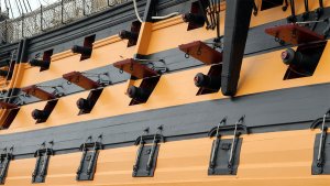
If you plan to rig sails and mount the guns you could show the gun ports open. If you don't have sails or they are not set , then perhaps the gun ports would be closed.
-

Win a Free Custom Engraved Brass Coin!!!
As a way to introduce our brass coins to the community, we will raffle off a free coin during the month of August. Follow link ABOVE for instructions for entering.
-

PRE-ORDER SHIPS IN SCALE TODAY!
The beloved Ships in Scale Magazine is back and charting a new course for 2026!
Discover new skills, new techniques, and new inspirations in every issue.
NOTE THAT OUR FIRST ISSUE WILL BE JAN/FEB 2026
You are using an out of date browser. It may not display this or other websites correctly.
You should upgrade or use an alternative browser.
You should upgrade or use an alternative browser.
Constructo 1799 Enterprise help
- Thread starter Pathfinder65
- Start date
- Watchers 30
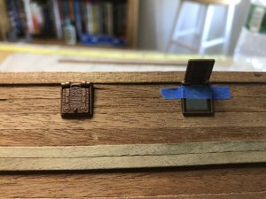
Hi Mike,If you plan to rig sails and mount the guns you could show the gun ports open. If you don't have sails or they are not set , then perhaps the gun ports would be closed.
Thank you for the comment. The gun port doors in the picture are a complete frame with a door that opens. I had just popped them into the
opening so I could get a picture and a feel of what they would look like on the hull
.
Last edited:
Interesting aside:
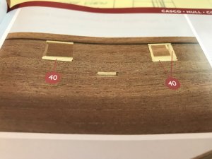 Step #40, framing the interior of the gun ports.
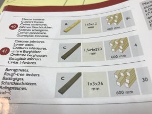 The pictorial instructions show the material for item #40, the thickness and width and cut length ( 1 X 5 X 12mm), the length of that material in the kit and the number of pieces to be cut (56).
But when one looks at the example picture of the gun port framing it is obvious that not all the framing pieces can be the same length. The horizontal pieces can be 12mm, but the vertical pieces length must be 2mm less. I think for this to work there must be 28 horizontal pieces @ 12mm and 28 vertical pieces @ 10mm.
 Step #40, framing the interior of the gun ports.
 The pictorial instructions show the material for item #40, the thickness and width and cut length ( 1 X 5 X 12mm), the length of that material in the kit and the number of pieces to be cut (56).
But when one looks at the example picture of the gun port framing it is obvious that not all the framing pieces can be the same length. The horizontal pieces can be 12mm, but the vertical pieces length must be 2mm less. I think for this to work there must be 28 horizontal pieces @ 12mm and 28 vertical pieces @ 10mm.
The correct measures you have to take directly at the gunports, one by one.
In prinpciple you are right, if the gunports are square with 12 to 12mm!
In prinpciple you are right, if the gunports are square with 12 to 12mm!
Hi Uwe,
I've checked the cut profile plan and the rigging plan and the gun ports measure a nominal 12 X 12 mm. My gun port cutouts are approximately 10 X 10 mm. I did that in case I decided to use the commercial gun port frames in my post #180. I'm still thinking about that..
I've checked the cut profile plan and the rigging plan and the gun ports measure a nominal 12 X 12 mm. My gun port cutouts are approximately 10 X 10 mm. I did that in case I decided to use the commercial gun port frames in my post #180. I'm still thinking about that..
Hi Uwe,
I've checked the cut profile plan and the rigging plan and the gun ports measure a nominal 12 X 12 mm. My gun port cutouts are approximately 10 X 10 mm. I did that in case I decided to use the commercial gun port frames in my post #180. I'm still thinking about that..
Related to the commercial gunports frames: they are not looking realistic if it is allowed to say....and this mainly because they are sitting on top of the hull planks. In reality the timber installed on the outside of the lids were exactly plane or on the same level like the hull planks. Means if the lids were closed, it was a more or less smooth surface. Also the timber of the lids followed the whales, not in your case of course.....I try to find a photo to explain it better.
I found some photos of the HMS Victory which are demonstrating and showing what I wanted to express in my bad english
The lids are shaped to follow the curve of the hull. and no frame was visible from outside, when they were closed
View attachment 40714 View attachment 40715
Hi Uwe,
Thank you for the excellent explanation and examples. I think I now understand how this should be modeled.
(BTW your English is much better than my German)
Gun Port Framing:
Yet another “how does one do this”. I’ve spent some time on the Forum reading build threads and looking at how the members tackle build problems.
I started to experiment cutting scrap pieces to the size recommended by the build instructions. Each gun port requires two pieces 12mm long and two pieces 10mm long. The challenge was to have square ends. First I tried cutting a piece to length with a razor saw. Holding the piece down and cutting at the same time wasn’t the answer. The sawed end wasn’t square. Off I went to the Hobby store and bought a modelers miter box made out of plastic. This time I clamped the scrap piece in the miter box and sawed away. The result was the same as my first try, the sawed end was not square and the sawing action deformed the vertical slot in the miter box. I ordered another modelers miter box, this time made from Aluminum and several saw blades with more TPI, thinking that would provide a finer precise cut.
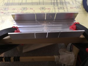
The result was about the same as my first two tries. The miter box has one extended leg, I had to clamp on a end stop for the length of the cut, clamp the scrap I was cutting, etc. The scrap piece cut to length was almost but not quite square.
Another internet search for a tool to better do the job resulted in this find.
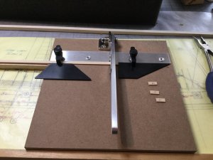
There were several styles available, I chose this one because of next day delivery. The little pieces on the right side of the cutter are 12mm and 11mm long. The cuts are square, and I can cut as many of the same size that I need without much effort.
Not bad research for a guy who recently celebrated his 55th anniversary of his 21st birthday, EH.
Yet another “how does one do this”. I’ve spent some time on the Forum reading build threads and looking at how the members tackle build problems.
I started to experiment cutting scrap pieces to the size recommended by the build instructions. Each gun port requires two pieces 12mm long and two pieces 10mm long. The challenge was to have square ends. First I tried cutting a piece to length with a razor saw. Holding the piece down and cutting at the same time wasn’t the answer. The sawed end wasn’t square. Off I went to the Hobby store and bought a modelers miter box made out of plastic. This time I clamped the scrap piece in the miter box and sawed away. The result was the same as my first try, the sawed end was not square and the sawing action deformed the vertical slot in the miter box. I ordered another modelers miter box, this time made from Aluminum and several saw blades with more TPI, thinking that would provide a finer precise cut.

The result was about the same as my first two tries. The miter box has one extended leg, I had to clamp on a end stop for the length of the cut, clamp the scrap I was cutting, etc. The scrap piece cut to length was almost but not quite square.
Another internet search for a tool to better do the job resulted in this find.

There were several styles available, I chose this one because of next day delivery. The little pieces on the right side of the cutter are 12mm and 11mm long. The cuts are square, and I can cut as many of the same size that I need without much effort.
Not bad research for a guy who recently celebrated his 55th anniversary of his 21st birthday, EH.
Last edited:
Another interesting build instruction error:
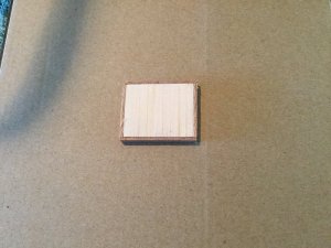
I’ve been working on framing gun ports most of the week and thought I might do something else today. I skipped forward to instructions for the hatches. The instructions for cutting the pieces for the smaller hatch at the bow are at odds dimension wise with the deck plan.
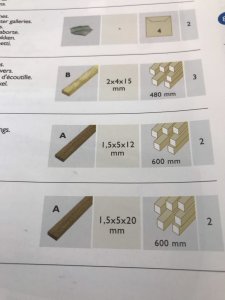
The the instructions show the thickness, width and length of the material as well as the number of pieces required.
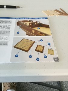
The picture above shows the forward hatch build. The problem with the build as shown is when parts #84 ( 1.5X5X12mm) are placed inside of part #85 (1.5X5X20mm), parts #83 (2X4X15mm) are 2mm short of filling the frame made by parts #84 & #85.
The test of the theory is shown below. I placed the partially completed hatch on the deck plan and found the dimensions on the plan were not the same as the build instructions. The orientation of the top and side pieces was also different.
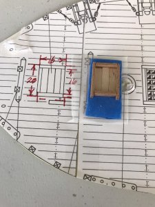
My fix will be to trim the extra 2mm from the longer side.
I’ve been working on framing gun ports most of the week and thought I might do something else today. I skipped forward to instructions for the hatches. The instructions for cutting the pieces for the smaller hatch at the bow are at odds dimension wise with the deck plan.

The the instructions show the thickness, width and length of the material as well as the number of pieces required.

The picture above shows the forward hatch build. The problem with the build as shown is when parts #84 ( 1.5X5X12mm) are placed inside of part #85 (1.5X5X20mm), parts #83 (2X4X15mm) are 2mm short of filling the frame made by parts #84 & #85.
The test of the theory is shown below. I placed the partially completed hatch on the deck plan and found the dimensions on the plan were not the same as the build instructions. The orientation of the top and side pieces was also different.

My fix will be to trim the extra 2mm from the longer side.
The Hatch:
...........
I’ve also learned to double check the instructions for a build part and double check the plans to verify dimensions.
Learning every day......and never stop to learn.....well done
Hi Uwe,
Thank you for your comments and likes.
Thank you for your comments and likes.
More how do you this.
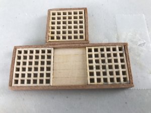
I looked at the build instructions for the gratings and decided that process was simple enough. I glued together three sets and noticed that the grates had to fit into a 21mm by 65mm and 21mm by 26mm frames. But, the grating edges extended beyond the dimension of the frames.
So, another “jig”. Blue masking tape and a mini saw. I found by using a little Bees wax on the saw blade the cuts went quickly without any binding.
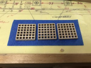
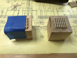
As Uwe has noted several times, this is a great learning experience for a novice builder.
I looked at the build instructions for the gratings and decided that process was simple enough. I glued together three sets and noticed that the grates had to fit into a 21mm by 65mm and 21mm by 26mm frames. But, the grating edges extended beyond the dimension of the frames.
So, another “jig”. Blue masking tape and a mini saw. I found by using a little Bees wax on the saw blade the cuts went quickly without any binding.


As Uwe has noted several times, this is a great learning experience for a novice builder.
Another little foible:
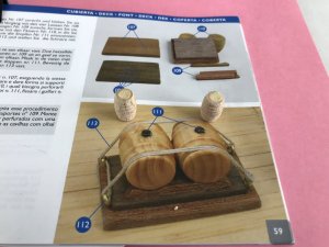
This little build looked simple enough. I made the platforms and then looked at the barrels. One end was a shown in the build instructions but the other end has 1mm or more indent. The choice was to sand that end or fill it. I chose the latter. I found some old Balsa filler in my RC airplane flying box ( another old hobby). We will see how that works.

This little build looked simple enough. I made the platforms and then looked at the barrels. One end was a shown in the build instructions but the other end has 1mm or more indent. The choice was to sand that end or fill it. I chose the latter. I found some old Balsa filler in my RC airplane flying box ( another old hobby). We will see how that works.
More Tools: Sanding Detailers.
I discovered these while ordering some #11 cutting blades. I had made some sanding sticks from 3/8 X 3/8 square birch stringers. Those have worked very well. However these detail sanders looked like they might work for some of the smaller details in the build.
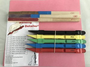
I’ll let you know how they work out.
I discovered these while ordering some #11 cutting blades. I had made some sanding sticks from 3/8 X 3/8 square birch stringers. Those have worked very well. However these detail sanders looked like they might work for some of the smaller details in the build.

I’ll let you know how they work out.
More Tools: Sanding Detailers.
I’ll let you know how they work out.
They are looking interesting.....so please give us later your opinion....how much is the price for them?
They are looking interesting.....so please give us later your opinion....how much is the price for them?
I got them from Amazon.
https://www.amazon.com/Piece-Sandin...d=1527522731&sr=8-4&keywords=sanding+detailer
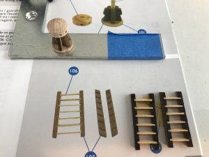
I just used the finer grid 240 and 400 to clean up the hatches, capstan and ladders before I varnish those.


