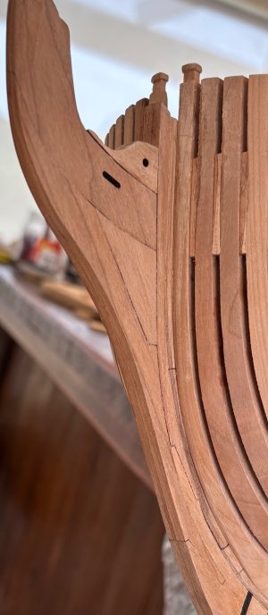
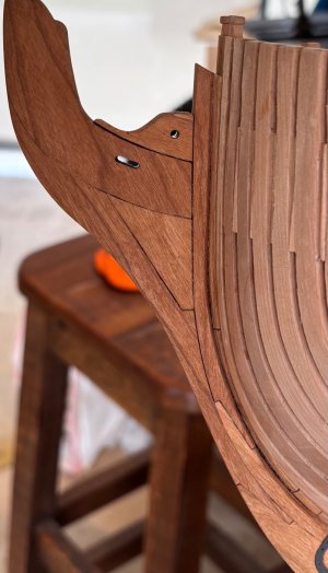
• LUCZORAMA SHIPWRECK SCAVENGER HUNT GIVEAWAY. 4 Weeks of Fun • 1 Legendary Prize ((OcCre’s Fram Ship)) • Global Crew Welcome!
    **VIEW THREAD HERE**

HMS Enterprise 1774 POF 1:48.

I am learning about the actual ship building processes so my limited scratch builds will be included here and there.
Hi Grant,

Whatever you are doing, it is working,,,,,,,, very well!

In your learning about the ship building, what books/ sources are your favorites? Many members have a variety of books and other go to sources they like to use. I would bet members that are following your build would like to know your favorites be they books and/or contemporary sources such as the plans and contract for Enterprise.
Allan
Good evening Allan. I have a few books (downloads) which I refer to. Mostly I attempt to add a little extra to the kits I and scratch build some aspects where the kit design allows me too. I am resource limited so there cannot be too much change to the kits.

With this CAF Enterprise kit it was very clear early on that I would not be able to build it accurately in accordance with the original plans and contracts. The deviation is just too great. So I add accuracy where I can….sometimes it has to be limited. E.g. the partners and chock for the mast give a more accurate representation than the kit. I based these on Goodwin.

To bash this kit would mean starting from scratch - literally. Maybe one day I will attempt a proper accurate scratch ship but I need to learn plenty more and improve my skills a tad first.

My main reference is : The construction and fitting of the sailing Man of war 1650-1850 by Goodwin
I also refer to a summary of Structures of English wooden ships by William Sutherland from Trevor Ketchington. I think this was a thesis for a Canadian university. (Found this on the web. )

For my rigging I use ;
the Art of Rigging by George Biddlecombe- clearly I only use about 30% (on a good day ROTF) of this detail.
Masting treatise, mast making and rigging of ships by Rupert Kipping

I have some other books which I have not read totally and are very useful for understanding how things work:
Seamanship in the age of sail by Harland
Seamanship- US Naval by SB Luce

Lastly ChatGPT…… really gives some interesting insights but you have to check it. It has attempted to lead me astray a few timesROTF
Cheers Grant
 
Good morning.
Cutting gunports: Hmmmm……:mad:.

Through out this build the instructions and design of the kit have made this a fairly complex build. So far the challenges have been rather enjoyable and made for some brainstorming - always fun.

Gunports…..hmmm ROTF.
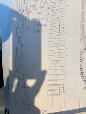
Firstly the two diagrams provided differ from each other so I decided to go with the one which showed the “end product”. The second diagram.
IMG_5780.jpeg
IMG_5781.jpeg
Unfortunately the frames in this diagram are not in sync with my ship so I cannot trust this either and “tossed” it.

The instructions use a dummy cannon jig which you use to mark the frames as a starting point. I marked each port using this method and using blocks of wood cut to size determined the size and position of the port.
IMG_5728.jpeg
As a double check I used The first diagram which frames do match up 100% to my ship. I cut this and stuck it to the ship.
IMG_5805.jpeg
The really cool thing is my decks and clamps match up to this diagram really well so that made me happy. I Marked each port.

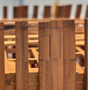
The ports per the plan and my calculations using the jig and measurements came out pretty close but not 100%. Obviously I need to include the stops, lintel and sills so the measured drawing is bigger than the one marked from the plan. Here are two examples:
IMG_5810.jpeg

IMG_5809.jpeg
2 differents methods 2 different results, two different diagrams, two different results……hmmm:mad:.
I then thought I had better check if I can add my spirketling.
IMG_5517.png
Works OK, but the kit is clearly not designed to take this and does not fit super cool with the port.Not glued just a look see.
IMG_5793.jpeg
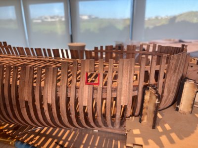
I cut the first port on SB side using a best guess methodROTF and added some stops, fake sill and lintel. (Not cut correctly or glued) just to see shape and colour.
IMG_5762.jpegIMG_5765.jpeg
I now need to try and get the measurements and placement right. For the 10th time:oops:.

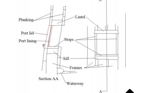
I will be showing one or two ports open. For these I will adjust the frames and add a proper lintel and sill as per this diagram:
IMG_5727.png
For all the ports with port lids I will use fake stops, lintels etc and plank according to this diagram:
IMG_5754.jpeg
For those without port lids, I will extend the stops to the plank level as the stops are not required- clearly. …..

Whew that took a while….ROTFROTF.

Cheers Grant
 
Good morning.
Cutting gunports: Hmmmm……:mad:.

Through out this build the instructions and design of the kit have made this a fairly complex build. So far the challenges have been rather enjoyable and made for some brainstorming - always fun.

Gunports…..hmmm ROTF.
Firstly the two diagrams provided differ from each other so I decided to go with the one which showed the “end product”. The second diagram.
View attachment 522584
View attachment 522585
Unfortunately the frames in this diagram are not in sync with my ship so I cannot trust this either and “tossed” it.

The instructions use a dummy cannon jig which you use to mark the frames as a starting point. I marked each port using this method and using blocks of wood cut to size determined the size and position of the port.
View attachment 522586
As a double check I used The first diagram which frames do match up 100% to my ship. I cut this and stuck it to the ship.
View attachment 522587
The really cool thing is my decks and clamps match up to this diagram really well so that made me happy. I Marked each port.

The ports per the plan and my calculations using the jig and measurements came out pretty close but not 100%. Obviously I need to include the stops, lintel and sills so the measured drawing is bigger than the one marked from the plan. Here are two examples:
View attachment 522588

View attachment 522589
2 differents methods 2 different results, two different diagrams, two different results……hmmm:mad:.
I then thought I had better check if I can add my spirketling.
View attachment 522590
Works OK, but the kit is clearly not designed to take this and does not fit super cool with the port.Not glued just a look see.
View attachment 522591
I cut the first port on SB side using a best guess methodROTF and added some stops, fake sill and lintel. (Not cut correctly or glued) just to see shape and colour.
View attachment 522592View attachment 522593
I now need to try and get the measurements and placement right. For the 10th time:oops:.

I will be showing one or two ports open. For these I will adjust the frames and add a proper lintel and sill as per this diagram:
View attachment 522595
For all the ports with port lids I will use fake stops, lintels etc and plank according to this diagram:
View attachment 522594
For those without port lids, I will extend the stops to the plank level as the stops are not required- clearly. …..

Whew that took a while….ROTFROTF.

Cheers Grant
Awesome job Grant, the challenges, the calculations, decisions about what is right or wrong make for an enjoyable build. Well, most of the time. ROTF Keep up the great work!
 
Good morning.
Cutting gunports: Hmmmm……:mad:.

Through out this build the instructions and design of the kit have made this a fairly complex build. So far the challenges have been rather enjoyable and made for some brainstorming - always fun.

Gunports…..hmmm ROTF.
Firstly the two diagrams provided differ from each other so I decided to go with the one which showed the “end product”. The second diagram.
View attachment 522584
View attachment 522585
Unfortunately the frames in this diagram are not in sync with my ship so I cannot trust this either and “tossed” it.

The instructions use a dummy cannon jig which you use to mark the frames as a starting point. I marked each port using this method and using blocks of wood cut to size determined the size and position of the port.
View attachment 522586
As a double check I used The first diagram which frames do match up 100% to my ship. I cut this and stuck it to the ship.
View attachment 522587
The really cool thing is my decks and clamps match up to this diagram really well so that made me happy. I Marked each port.

The ports per the plan and my calculations using the jig and measurements came out pretty close but not 100%. Obviously I need to include the stops, lintel and sills so the measured drawing is bigger than the one marked from the plan. Here are two examples:
View attachment 522588

View attachment 522589
2 differents methods 2 different results, two different diagrams, two different results……hmmm:mad:.
I then thought I had better check if I can add my spirketling.
View attachment 522590
Works OK, but the kit is clearly not designed to take this and does not fit super cool with the port.Not glued just a look see.
View attachment 522591
I cut the first port on SB side using a best guess methodROTF and added some stops, fake sill and lintel. (Not cut correctly or glued) just to see shape and colour.
View attachment 522592View attachment 522593
I now need to try and get the measurements and placement right. For the 10th time:oops:.

I will be showing one or two ports open. For these I will adjust the frames and add a proper lintel and sill as per this diagram:
View attachment 522595
For all the ports with port lids I will use fake stops, lintels etc and plank according to this diagram:
View attachment 522594
For those without port lids, I will extend the stops to the plank level as the stops are not required- clearly. …..

Whew that took a while….ROTFROTF.

Cheers Grant
I admire your perseverance Grant. But very understandable because sawing in the frames has to be right the first time. These first steps look good.
Regards, Peter
 
Wow, a complicated process. Lot's of imagineering involved.

Jan
Hi Jan. I think the CAF designers tried to be a little too smart and made this more complicated than it should be …. Or maybe I’m just a little slow;). I like it “imagineering” - says it all. Cheers Grant
Scary business cutting into the frames. I think you guys say 'holding thumbs'...
Good evening Paul. Yep not the best design. It is what it is and I must make it work. At least I have figured out where these must be cut now. I see the kit does not provide for the vent/oar ports. I need to do some research to find where they go on a frigate. With this admiralty design I may have to plank and then cut these but I would prefer to create these into the frames now….hmmmm. .Cheers Grant
Excellent informative post Grant, the included references help explain your thought process. Your ability to adjust and adapt is impressive.
Good evening Roger. I think my adjust and adapt powers are an illusion of actually having no idea……”fake it till you make it” some sayROTF. Seriously tho thank you.Cheers Grant
I admire your perseverance Grant. But very understandable because sawing in the frames has to be right the first time. These first steps look good.
Regards, Peter
True story Peter. Once I hack into those frames there is no coming back.
Great results come from multiple references (2 kit drawings and several outside drawings)!!

Then there is your precise execution and great documentation of your methods.

Can't wait to see the results of both the closed and open gunports!!
Thanks Brad. Hopefully my results will be ok. I am changing this kit up completely and going to try and give it a bit of character…. It will either work or fail miserably…..the open gun ports will be part of this look. Still a way off tho. Cheers Grant
 
Good morning.
Cutting gunports: Hmmmm……:mad:.

Through out this build the instructions and design of the kit have made this a fairly complex build. So far the challenges have been rather enjoyable and made for some brainstorming - always fun.

Gunports…..hmmm ROTF.
Firstly the two diagrams provided differ from each other so I decided to go with the one which showed the “end product”. The second diagram.
View attachment 522584
View attachment 522585
Unfortunately the frames in this diagram are not in sync with my ship so I cannot trust this either and “tossed” it.

The instructions use a dummy cannon jig which you use to mark the frames as a starting point. I marked each port using this method and using blocks of wood cut to size determined the size and position of the port.
View attachment 522586
As a double check I used The first diagram which frames do match up 100% to my ship. I cut this and stuck it to the ship.
View attachment 522587
The really cool thing is my decks and clamps match up to this diagram really well so that made me happy. I Marked each port.

The ports per the plan and my calculations using the jig and measurements came out pretty close but not 100%. Obviously I need to include the stops, lintel and sills so the measured drawing is bigger than the one marked from the plan. Here are two examples:
View attachment 522588

View attachment 522589
2 differents methods 2 different results, two different diagrams, two different results……hmmm:mad:.
I then thought I had better check if I can add my spirketling.
View attachment 522590
Works OK, but the kit is clearly not designed to take this and does not fit super cool with the port.Not glued just a look see.
View attachment 522591
I cut the first port on SB side using a best guess methodROTF and added some stops, fake sill and lintel. (Not cut correctly or glued) just to see shape and colour.
View attachment 522592View attachment 522593
I now need to try and get the measurements and placement right. For the 10th time:oops:.

I will be showing one or two ports open. For these I will adjust the frames and add a proper lintel and sill as per this diagram:
View attachment 522595
For all the ports with port lids I will use fake stops, lintels etc and plank according to this diagram:
View attachment 522594
For those without port lids, I will extend the stops to the plank level as the stops are not required- clearly. …..

Whew that took a while….ROTFROTF.

Cheers Grant
Masterfully done !
 
Back
Top