-

Win a Free Custom Engraved Brass Coin!!!
As a way to introduce our brass coins to the community, we will raffle off a free coin during the month of August. Follow link ABOVE for instructions for entering.
- Home
- Forums
- Ships of Scale Group Builds and Projects
- HMS Alert 1777 1:48 PoF Group Build
- HMS Alert 1777 1:48 Group Build Logs
You are using an out of date browser. It may not display this or other websites correctly.
You should upgrade or use an alternative browser.
You should upgrade or use an alternative browser.
HMS Alert [1777] 1:48 POF by serikoff. (Two hulls: skeleton and fully rigged)
Thank you very much. Yes, we doctors, like craftsmen, must be able to develop our fine motor skills. But still, thanks for the praise. And yes, you are right about the powder monkeys.. I read about it and the Horatio Hornblower series showed it well.Hello Sergey,
the figure turned out really nice and your construction is just great. No wonder you work so delicately. After all, you are a dentist and certainly a very good one!
Cheers Günther
Beams and Carlengs (body fit).
All preparatory moments are over and the upper deck can be assembled. And as always - first a little theory.
Anatomy drawings show how Beams and carlengs should be placed. But it is also clearly visible that some longitudinal slats (which strengthened the deck boards from deflection) of different widths. If you miss the moment of insignificant differences, then in addition to the standard size there are reinforced slats that were thicker. On my scale, it's 1.8 and 3mm respectively. I marked the latter in yellow.
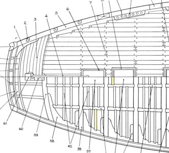
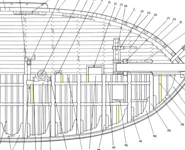
In addition to those places where the slats are smaller in number and made thicker for reinforcement, there are also places where such slats were placed around the hatches or to strengthen vertical elements.
It was simplified in the set, but I decided to add this point. Plus, I decided to completely redo the workpieces for all these rails.

First, the wood for the slats from the set is lighter and spotty. And secondly, and most importantly, the structure of the side surfaces is very ugly, which is clearly visible in the bottom photo.
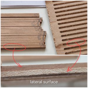
Plus, the slats are cut in a strange way (it would be better if they were cut on a saw), otherwise the fibers remained from boron, which will need to be constantly removed.
But before assembling the deck, you need to understand one of the most important points!
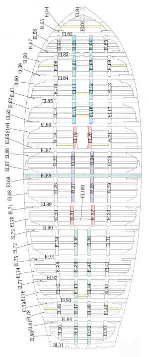
The two inner bands of elings (carlings) run strictly parallel to each other and naturally perpendicular to beams. And they are divided into several groups. For clarity, I marked them with different colors. In front, the blue 4 pairs are parallel in 2 lines. Rear 5 pairs of greens similarly. Well, according to the same principle, 2 pairs of purple and separately in a pair of red.
Why am I all.. It is necessary to place the longitudinal elements so that they are strictly parallel and perpendicular (excluding any diagonals) otherwise the deck will walk back and forth from the foreground and background.
The two side strips run as if in an arc, and beam 88 separates them. In a real ship and anatomy, the longitudinal elements really went along small arcs, but the kit manufacturer simplified this and made the assembly easier by shifting the slots. Since all the elements go perpendicular to the beams but with a slight offset, so that in general it seems that this is an arc, but in fact they hit the steps. I hope I explained it clearly.
Now, chronologically, how I collected everything in order:
First, I fitted the front element of the deck (knee) along the profile so that it sat in place.
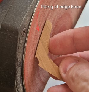
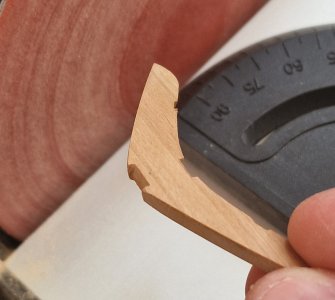
Then I created a flat edge of Carlengs. Since they were almost perfectly fitted in length, there were slight irregularities at the end. Therefore, I slightly touched the grinder and pressed the side surface to the disk, creating an even edge. The main thing is not to overdo it, since all this is approximately 0.1 mm no more.
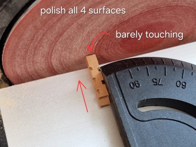
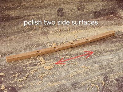
Then on the sandpaper canvas, I polished all 4 surfaces.
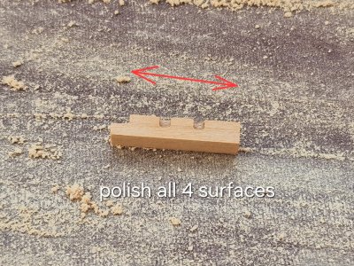
I did the same with the sides of the beams.
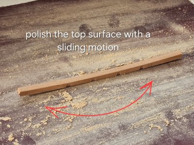
The upper surface can be polished by sliding rolling motions.
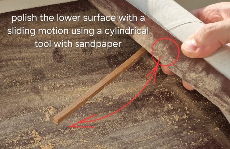
And I polished the bottom surface with sandpaper wrapped on a large cylinder.
Then I clipped the excess at the edges of the beams.
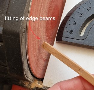
I didn't make any adaptations to accurately calculate the length of the beams, as they should be slightly shorter than where they are, but not much to avoid falling out. And why so - I will tell you below.
Since the length of the carlengs has already been calibrated, part of the holly can be assembled without glue.
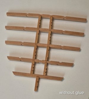
I collected naturally inside the hull, but for clarity I showed that the deck can be safely removed without glue and it can stick together.
And here is the build order:
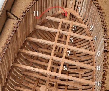
First, I adjusted the front knee, then I adjusted the beams and nearby cardings in groups. And only then the very first carleng. Since the space between beams is more important, and then you can adjust the space between beams and knee.
The second very important point that I have already mentioned is the distance between the beams and the body. It is necessary in order to be able to slightly shift the beams to the right or left, thus it is possible to adjust the evenness of the lines of carleng, which should be strictly parallel.
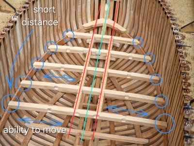
This is probably the biggest trick in deck assembly. The place in the blue circle will not be visible at all. On the side of the knee, on top of the drainage, and outside the skin. Therefore, a small gap will not be visible, but the ability to move beams is very important for building good geometry. And yet, do not glue everything as you fit. It is better to collect everything without glue and then if it is necessary to edit the geometry, if something has become crooked, otherwise if you glue, it will already be so.
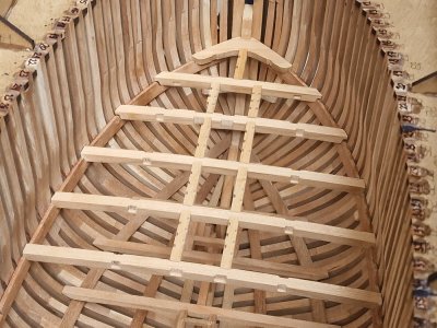
I haven't cut the bottom of the carlengs into the beams and slats into the carlengs yet, that will be later. In the meantime, I like the way it looks and the pace... thought it would be slower...
P.S. Oh yes, in the instructions, or rather, in the drawings of their set, the right and left sides are mixed up. Intuitively, everything is clear, but still - you need not to forget about it. (this concerns the set from AliExpress)
All preparatory moments are over and the upper deck can be assembled. And as always - first a little theory.
Anatomy drawings show how Beams and carlengs should be placed. But it is also clearly visible that some longitudinal slats (which strengthened the deck boards from deflection) of different widths. If you miss the moment of insignificant differences, then in addition to the standard size there are reinforced slats that were thicker. On my scale, it's 1.8 and 3mm respectively. I marked the latter in yellow.


In addition to those places where the slats are smaller in number and made thicker for reinforcement, there are also places where such slats were placed around the hatches or to strengthen vertical elements.
It was simplified in the set, but I decided to add this point. Plus, I decided to completely redo the workpieces for all these rails.

First, the wood for the slats from the set is lighter and spotty. And secondly, and most importantly, the structure of the side surfaces is very ugly, which is clearly visible in the bottom photo.

Plus, the slats are cut in a strange way (it would be better if they were cut on a saw), otherwise the fibers remained from boron, which will need to be constantly removed.
But before assembling the deck, you need to understand one of the most important points!

The two inner bands of elings (carlings) run strictly parallel to each other and naturally perpendicular to beams. And they are divided into several groups. For clarity, I marked them with different colors. In front, the blue 4 pairs are parallel in 2 lines. Rear 5 pairs of greens similarly. Well, according to the same principle, 2 pairs of purple and separately in a pair of red.
Why am I all.. It is necessary to place the longitudinal elements so that they are strictly parallel and perpendicular (excluding any diagonals) otherwise the deck will walk back and forth from the foreground and background.
The two side strips run as if in an arc, and beam 88 separates them. In a real ship and anatomy, the longitudinal elements really went along small arcs, but the kit manufacturer simplified this and made the assembly easier by shifting the slots. Since all the elements go perpendicular to the beams but with a slight offset, so that in general it seems that this is an arc, but in fact they hit the steps. I hope I explained it clearly.
Now, chronologically, how I collected everything in order:
First, I fitted the front element of the deck (knee) along the profile so that it sat in place.


Then I created a flat edge of Carlengs. Since they were almost perfectly fitted in length, there were slight irregularities at the end. Therefore, I slightly touched the grinder and pressed the side surface to the disk, creating an even edge. The main thing is not to overdo it, since all this is approximately 0.1 mm no more.

Then on the sandpaper canvas, I polished all 4 surfaces.

I did the same with the sides of the beams.

The upper surface can be polished by sliding rolling motions.

And I polished the bottom surface with sandpaper wrapped on a large cylinder.

Then I clipped the excess at the edges of the beams.

I didn't make any adaptations to accurately calculate the length of the beams, as they should be slightly shorter than where they are, but not much to avoid falling out. And why so - I will tell you below.
Since the length of the carlengs has already been calibrated, part of the holly can be assembled without glue.

I collected naturally inside the hull, but for clarity I showed that the deck can be safely removed without glue and it can stick together.
And here is the build order:

First, I adjusted the front knee, then I adjusted the beams and nearby cardings in groups. And only then the very first carleng. Since the space between beams is more important, and then you can adjust the space between beams and knee.
The second very important point that I have already mentioned is the distance between the beams and the body. It is necessary in order to be able to slightly shift the beams to the right or left, thus it is possible to adjust the evenness of the lines of carleng, which should be strictly parallel.

This is probably the biggest trick in deck assembly. The place in the blue circle will not be visible at all. On the side of the knee, on top of the drainage, and outside the skin. Therefore, a small gap will not be visible, but the ability to move beams is very important for building good geometry. And yet, do not glue everything as you fit. It is better to collect everything without glue and then if it is necessary to edit the geometry, if something has become crooked, otherwise if you glue, it will already be so.

I haven't cut the bottom of the carlengs into the beams and slats into the carlengs yet, that will be later. In the meantime, I like the way it looks and the pace... thought it would be slower...
P.S. Oh yes, in the instructions, or rather, in the drawings of their set, the right and left sides are mixed up. Intuitively, everything is clear, but still - you need not to forget about it. (this concerns the set from AliExpress)
Last edited:
Nicely documented and executed, Sergey. Chapeaux!5.2. Beams and Carlengs (body fit).
All preparatory moments are over and the upper deck can be assembled. And as always - first a little theory.
Anatomy drawings show how Beams and carlengs should be placed. But it is also clearly visible that some longitudinal slats (which strengthened the deck boards from deflection) of different widths. If you miss the moment of insignificant differences, then in addition to the standard size there are reinforced slats that were thicker. On my scale, it's 1.8 and 3mm respectively. I marked the latter in yellow.
View attachment 525729
View attachment 525731
In addition to those places where the slats are smaller in number and made thicker for reinforcement, there are also places where such slats were placed around the hatches or to strengthen vertical elements.
It was simplified in the set, but I decided to add this point. Plus, I decided to completely redo the workpieces for all these rails.
View attachment 525732
First, the wood for the slats from the set is lighter and spotty. And secondly, and most importantly, the structure of the side surfaces is very ugly, which is clearly visible in the bottom photo.
View attachment 525733
Plus, the slats are cut in a strange way (it would be better if they were cut on a saw), otherwise the fibers remained from boron, which will need to be constantly removed.
But before assembling the deck, you need to understand one of the most important points!
View attachment 525734
The two inner bands of elings (carlings) run strictly parallel to each other and naturally perpendicular to beams. And they are divided into several groups. For clarity, I marked them with different colors. In front, the blue 4 pairs are parallel in 2 lines. Rear 5 pairs of greens similarly. Well, according to the same principle, 2 pairs of purple and separately in a pair of red.
Why am I all.. It is necessary to place the longitudinal elements so that they are strictly parallel and perpendicular (excluding any diagonals) otherwise the deck will walk back and forth from the foreground and background.
The two side strips run as if in an arc, and beam 88 separates them. In a real ship and anatomy, the longitudinal elements really went along small arcs, but the kit manufacturer simplified this and made the assembly easier by shifting the slots. Since all the elements go perpendicular to the beams but with a slight offset, so that in general it seems that this is an arc, but in fact they hit the steps. I hope I explained it clearly.
Now, chronologically, how I collected everything in order:
First, I fitted the front element of the deck (knee) along the profile so that it sat in place.
View attachment 525735
View attachment 525736
Then I created a flat edge of Carlengs. Since they were almost perfectly fitted in length, there were slight irregularities at the end. Therefore, I slightly touched the grinder and pressed the side surface to the disk, creating an even edge. The main thing is not to overdo it, since all this is approximately 0.1 mm no more.
View attachment 525737
Then on the sandpaper canvas, I polished all 4 surfaces.
View attachment 525741
I did the same with the sides of the beams.
View attachment 525742
The upper surface can be polished by sliding rolling motions.
View attachment 525743
And I polished the bottom surface with sandpaper wrapped on a large cylinder.
View attachment 525744
Then I clipped the excess at the edges of the beams.
View attachment 525745
I didn't make any adaptations to accurately calculate the length of the beams, as they should be slightly shorter than where they are, but not much to avoid falling out. And why so - I will tell you below.
Since the length of the carlengs has already been calibrated, part of the holly can be assembled without glue.
View attachment 525746
I collected naturally inside the hull, but for clarity I showed that the deck can be safely removed without glue and it can stick together.
And here is the build order:
View attachment 525747
First, I adjusted the front knee, then I adjusted the beams and nearby cardings in groups. And only then the very first carleng. Since the space between beams is more important, and then you can adjust the space between beams and knee.
The second very important point that I have already mentioned is the distance between the beams and the body. It is necessary in order to be able to slightly shift the beams to the right or left, thus it is possible to adjust the evenness of the lines of carleng, which should be strictly parallel.
View attachment 525752
This is probably the biggest trick in deck assembly. The place in the blue circle will not be visible at all. On the side of the knee, on top of the drainage, and outside the skin. Therefore, a small gap will not be visible, but the ability to move beams is very important for building good geometry. And yet, do not glue everything as you fit. It is better to collect everything without glue and then if it is necessary to edit the geometry, if something has become crooked, otherwise if you glue, it will already be so.
View attachment 525755
I haven't cut the bottom of the carlengs into the beams and slats into the carlengs yet, that will be later. In the meantime, I like the way it looks and the pace... thought it would be slower...
P.S. Oh yes, in the instructions, or rather, in the drawings of their set, the right and left sides are mixed up. Intuitively, everything is clear, but still - you need not to forget about it. (this concerns the set from AliExpress)
Regards, Peter
Thank you, I think it will be even more interesting further onNicely documented and executed, Sergey. Chapeaux!
Regards, Peter
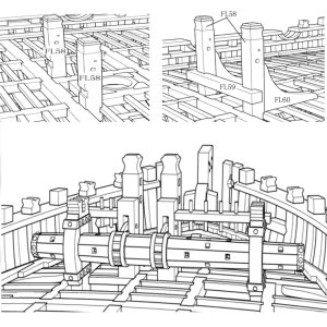
As already by tradition, let's start with the theory! In anatomy, two variants of the anchor mechanism (Windlass) are common and modified.
This is what the usual looks like.
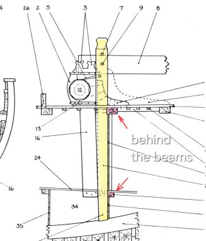
Pawl bitt pin (bar marked in yellow) is behind beams (marked in red).
And this is how the modified anchor mechanism (Windlass) looks like.
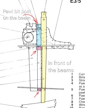
A couple more details appear (pawl bitt post) (marked in blue) and they are placed above the beam! And the Pawl bitt pin (bar marked in yellow) is in FRONT of the beams (marked in red).
And this is how the kit manufacturer came up with this node...
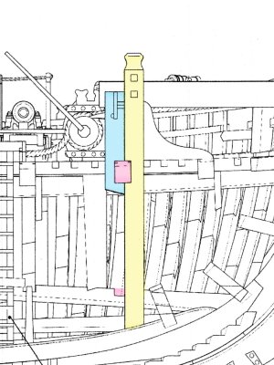
Pawl bitt post (marked blue) placed behind beams! And at the same time there is a tie-in both in the parts themselves and in the beam (which in such sizes is unacceptable due to the loss of strength of especially the beam). Pawl bitt pin (bar marked in yellow) is also in front of beams (marked in red), but with a large insert into beams, which is unacceptable for the same reason.
But unfortunately, you will have to do just that, because any displacements will lead to errors and not docking with other elements. But keep that in mind. That all this led to the fact that the instructions incorrectly indicated the grooves for Pawl bitt pin.
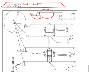
That is, according to the instructions, the grooves are placed behind the beam, although they should be in front of it!!!
Therefore, I decided to assemble the anchor mechanism, and for one and the winch mechanism, in order to accurately fit these elements into the hull before assembling the deck, and this is very important!
To do this, I extracted all the parts from the dies (only wooden).
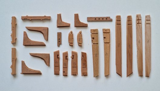
Then he removed all the holders from the parts of the winch. (we will not talk about her today).
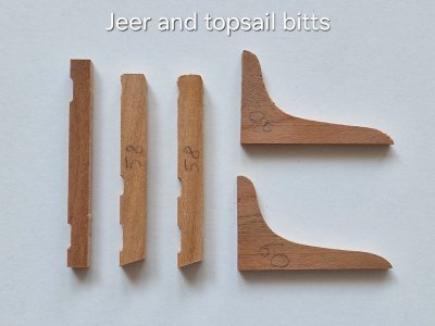
And here are the details of the anchor mechanism, so we need them...
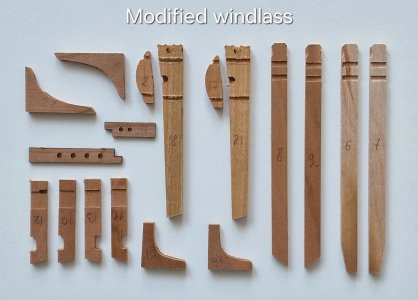
Details 6,7,8,9 are two bars Pawl bitt pin. They first need to be glued together. Before that, polishing the gluing place for perfect docking.
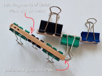
I did not glue the Pawl bitt post parts, since they still need to be refined, but now I only need their dimensions. I connected both pairs of these above parts to the beam and saw the gap...
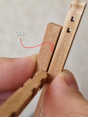
I had to cut the beams even more to eliminate this gap.
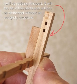
By the way, I will be redoing the Pawl bitt pin for many reasons. First, they should not be two-part. Secondly, the wood of these parts is very light and very mottled, which is very infuriating. It is a pity that almost all beams with such spotting... but I definitely won't redo them.
Now there will be immediately a continuation of this part...
...
This is what the usual looks like.

Pawl bitt pin (bar marked in yellow) is behind beams (marked in red).
And this is how the modified anchor mechanism (Windlass) looks like.

A couple more details appear (pawl bitt post) (marked in blue) and they are placed above the beam! And the Pawl bitt pin (bar marked in yellow) is in FRONT of the beams (marked in red).
And this is how the kit manufacturer came up with this node...

Pawl bitt post (marked blue) placed behind beams! And at the same time there is a tie-in both in the parts themselves and in the beam (which in such sizes is unacceptable due to the loss of strength of especially the beam). Pawl bitt pin (bar marked in yellow) is also in front of beams (marked in red), but with a large insert into beams, which is unacceptable for the same reason.
But unfortunately, you will have to do just that, because any displacements will lead to errors and not docking with other elements. But keep that in mind. That all this led to the fact that the instructions incorrectly indicated the grooves for Pawl bitt pin.

That is, according to the instructions, the grooves are placed behind the beam, although they should be in front of it!!!
Therefore, I decided to assemble the anchor mechanism, and for one and the winch mechanism, in order to accurately fit these elements into the hull before assembling the deck, and this is very important!

To do this, I extracted all the parts from the dies (only wooden).

Then he removed all the holders from the parts of the winch. (we will not talk about her today).

And here are the details of the anchor mechanism, so we need them...

Details 6,7,8,9 are two bars Pawl bitt pin. They first need to be glued together. Before that, polishing the gluing place for perfect docking.

I did not glue the Pawl bitt post parts, since they still need to be refined, but now I only need their dimensions. I connected both pairs of these above parts to the beam and saw the gap...

I had to cut the beams even more to eliminate this gap.

By the way, I will be redoing the Pawl bitt pin for many reasons. First, they should not be two-part. Secondly, the wood of these parts is very light and very mottled, which is very infuriating. It is a pity that almost all beams with such spotting... but I definitely won't redo them.
Now there will be immediately a continuation of this part...
...
... continuation of the previous post!
Now I have a place for fixing the beam on the upper beam and it remains to find a place for fixing to the lower beam, and naturally a place for fixing the beams from below, to the hull of the ship. All this needs to be adjusted to the fixation of the upper deck, otherwise it will not be possible to get there later.
And for this you need to assemble part of the upper deck for the upper stop (limitation) of the beams.
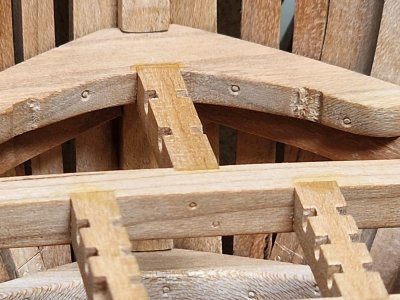
To connect beams and carlengs, you need to cut a little second to make them flush.
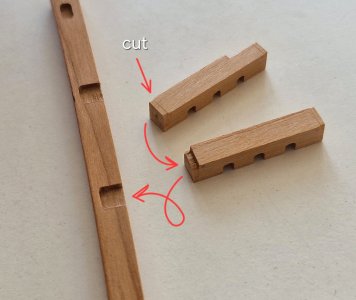
To know exactly how much to cut, you need to insert carleng into the beam and mark the cut line with the blade from below. Then carefully cut off the excess. Even if you cut a lot, it will still be hidden inside the beam, the main thing is to glue it flush with the upper surface.
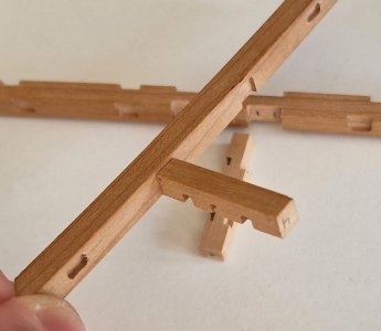
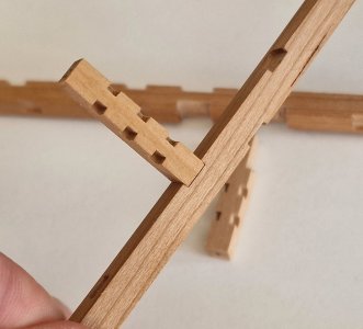
After that, I glued two middle carleng to the first beam.
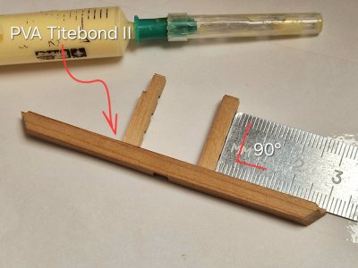
Used PVA and ruler to keep parts perpendicular!
It is advisable to immediately remove excess glue, especially in places where it is not possible to grind otherwise there will be stains after coating with oil. The top surface will be polished, it is permissible on it.
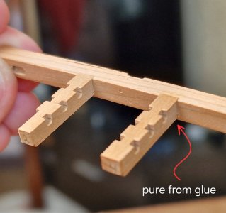
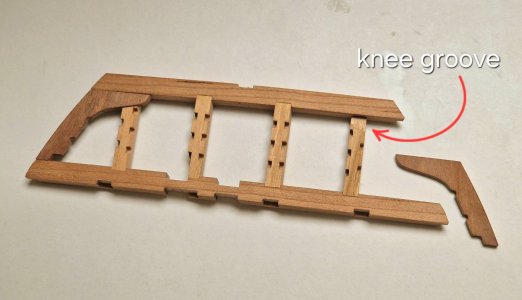
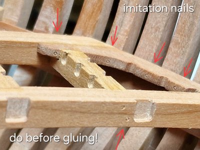
Also, we must not forget about imitation of nails. it must be done BEFORE gluing. Then it will be to put it mildly - not convenient.
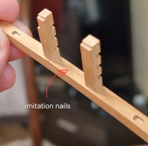
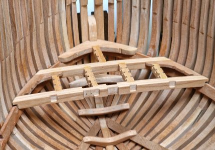
Thus, I glued together the two front beams and glued two knees along the docks. By the way, they crash into the side carlеngs!
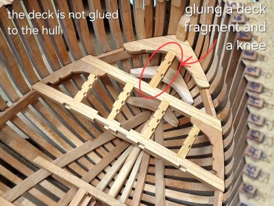
Then I glued that piece of deck through one carling to the front canopy, but I DIDN'T stick it all into the hull.
Naturally, before all gluing, you need to make imitation of nails (bolts) everywhere.
After everything sticks together, you can get this piece of the deck...
... and glue the side members.
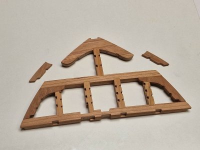
I glued them not in the hull, as they are too small to hold them well, plus they completely sat down.
After that, I fastened the elements of the anchor mechanism with rubber bands and now you can accurately calculate and shorten them in length...
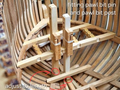
... and the main thing is to determine the correct position of the grooves for the bars (pin) in the lower beam.
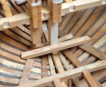
Actually, for this, all the manipulations were done! In order to finally complete the lower deck and before fixing the upper one, it was possible to cover everything with oil to the level of the upper deck, since after fixing it it it will be sooo difficult, if at all possible.
P.S. and also, a small spoiler... I printed my second case on a 3D printer... but I'll tell you about it later, I still need to show the scan model... will be interesting!
...
Now I have a place for fixing the beam on the upper beam and it remains to find a place for fixing to the lower beam, and naturally a place for fixing the beams from below, to the hull of the ship. All this needs to be adjusted to the fixation of the upper deck, otherwise it will not be possible to get there later.
And for this you need to assemble part of the upper deck for the upper stop (limitation) of the beams.
To connect beams and carlengs, you need to cut a little second to make them flush.

To know exactly how much to cut, you need to insert carleng into the beam and mark the cut line with the blade from below. Then carefully cut off the excess. Even if you cut a lot, it will still be hidden inside the beam, the main thing is to glue it flush with the upper surface.


After that, I glued two middle carleng to the first beam.

Used PVA and ruler to keep parts perpendicular!
It is advisable to immediately remove excess glue, especially in places where it is not possible to grind otherwise there will be stains after coating with oil. The top surface will be polished, it is permissible on it.

Also, we must not forget about imitation of nails. it must be done BEFORE gluing. Then it will be to put it mildly - not convenient.

Thus, I glued together the two front beams and glued two knees along the docks. By the way, they crash into the side carlеngs!

Then I glued that piece of deck through one carling to the front canopy, but I DIDN'T stick it all into the hull.

Naturally, before all gluing, you need to make imitation of nails (bolts) everywhere.


After everything sticks together, you can get this piece of the deck...

... and glue the side members.

I glued them not in the hull, as they are too small to hold them well, plus they completely sat down.
After that, I fastened the elements of the anchor mechanism with rubber bands and now you can accurately calculate and shorten them in length...

... and the main thing is to determine the correct position of the grooves for the bars (pin) in the lower beam.

Actually, for this, all the manipulations were done! In order to finally complete the lower deck and before fixing the upper one, it was possible to cover everything with oil to the level of the upper deck, since after fixing it it it will be sooo difficult, if at all possible.
P.S. and also, a small spoiler... I printed my second case on a 3D printer... but I'll tell you about it later, I still need to show the scan model... will be interesting!
...
Another sequel...
To finally close the issue with the lower deck - I lay out work on the final beam.
By the way, I do not plan to do even minimal or partial plating of the lower deck with boards. Even in places where there will be stairs - they will soar in the air if in life they rested only on the deck board. I also do not plan to install the boiler inside the ship. I looked at the photos of other masters, well, the boiler is very much lost there behind all the details of the deck. In the set, the boiler is a work of art and I think I will collect it and install it on a stand near the ship. There is a boiler on one side and a pair of anchors on the other. Such a kind of installation, and all this can be well considered. But this is still in the plans, everything needs to be checked.
In the meantime, after fitting, I made grooves for the bars and glued the final beam of the lower deck. I had to make these grooves with a margin, a little wider, to avoid if later it would be necessary to adjust the position of the beam. Since this place will be covered by an anchor mechanism, this is not a problem.
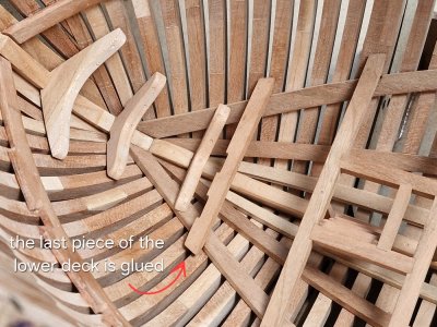
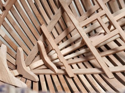
And this is how Pawl bitt pins bars will be installed in the future.
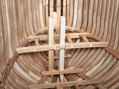
I adjusted them in length and when I redo them, I just need to repeat all the sizes on the new ones.
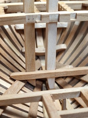
Well, as they say, now the lower deck is ready. You just need to make an imitation of nails outside the case, glue the keel and can be covered with oil... This is what you want most... though fearful, seeing a tree under butter is a thrill.
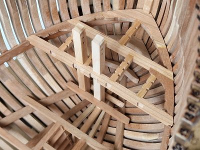
In the meantime, in anticipation, I will soon go for the second case printed on a 3D printer... eh, how much work there will be on it.

To finally close the issue with the lower deck - I lay out work on the final beam.
By the way, I do not plan to do even minimal or partial plating of the lower deck with boards. Even in places where there will be stairs - they will soar in the air if in life they rested only on the deck board. I also do not plan to install the boiler inside the ship. I looked at the photos of other masters, well, the boiler is very much lost there behind all the details of the deck. In the set, the boiler is a work of art and I think I will collect it and install it on a stand near the ship. There is a boiler on one side and a pair of anchors on the other. Such a kind of installation, and all this can be well considered. But this is still in the plans, everything needs to be checked.
In the meantime, after fitting, I made grooves for the bars and glued the final beam of the lower deck. I had to make these grooves with a margin, a little wider, to avoid if later it would be necessary to adjust the position of the beam. Since this place will be covered by an anchor mechanism, this is not a problem.


And this is how Pawl bitt pins bars will be installed in the future.

I adjusted them in length and when I redo them, I just need to repeat all the sizes on the new ones.

Well, as they say, now the lower deck is ready. You just need to make an imitation of nails outside the case, glue the keel and can be covered with oil... This is what you want most... though fearful, seeing a tree under butter is a thrill.

In the meantime, in anticipation, I will soon go for the second case printed on a 3D printer... eh, how much work there will be on it.

Very fine work, Sergey! You have my admiration.
Thank you very much. Come on, start something new so that I can continue to admire your work.Very fine work, Sergey! You have my admiration.
New work has a link in my signature...Thank you very much. Come on, start something new so that I can continue to admire your work.
- Joined
- Jul 27, 2021
- Messages
- 400
- Points
- 323

IndeedThis smiley means - wow. We were just amazed that you finally started a new project and we are very happy about it
View attachment 526281
Chapter 5. 2nd Hull
The chapter will consist of several parts:
5.1 3D scan | print (preparation of 2nd hull),
5.2 Imitation of bolts and fixation of keel to the 1st hull
I have previously shown that I scanned my body with a 3D scanner.
At this link you can see how it was.
Why do I need it. The whole review is called - "two hulls, one skeleton, the other in full armament (with cladding and sails)."
So, in order not to do the case again, so that later I could completely cover it with a skin, I scanned it. And now I will print it on a 3D printer. I will talk about this in detail, but for now - here is the project for printing after scanning. Later I will show how it was all printed, it is interesting for myself...
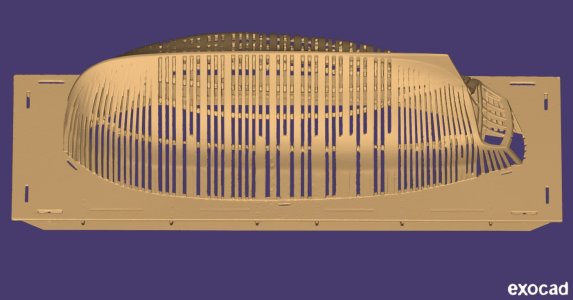
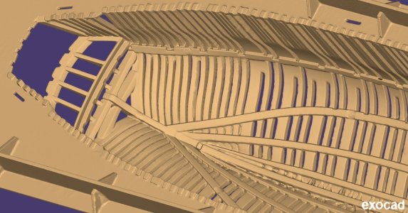
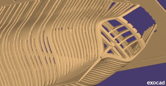
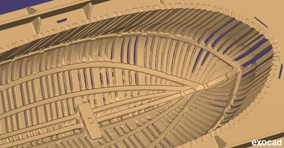
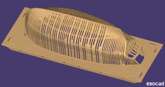
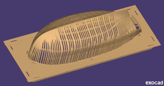
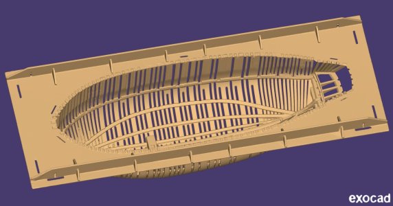
Now I will show you what came of it after printing...
Last edited:
Continuation to previous post...
So... the hull is already printed, and yesterday I took it in this state...
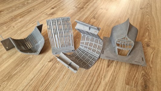
Printing, of course, is not as detailed as possible, but this is not the main thing here. And most importantly, the geometry is 1:1 with what I built and it can be sheathed with slats.
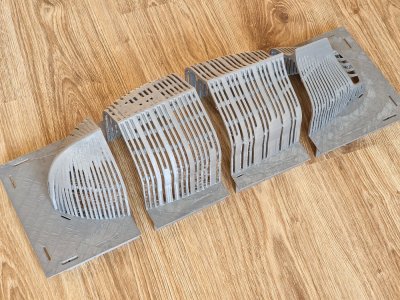
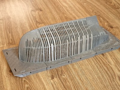
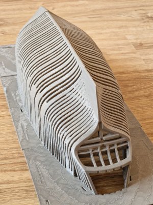
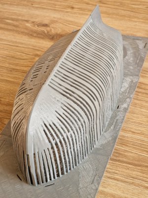
Today I glued it to CA gel and sanded it.
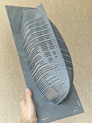
And surprisingly, the printed hull is very stable, very rigid and perfectly assembled. That is, there was no error in assembly.
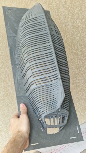
If you try to bend it with your fingers, then the stiffness feels like with a wooden version. This made me very happy, as did this joint appearance...
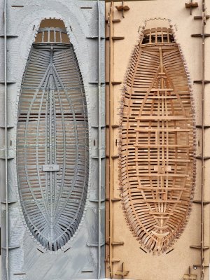
And most importantly, as you noticed, I specially made the structure together with the base (slipway cover) and this is necessary for many reasons. Rigidity, accuracy, positioning and compatibility with the existing slipway.
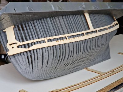
And now I was able to connect a template from the slice kit...
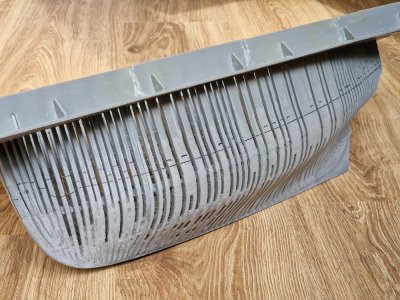
... and for now, everything is going according to plan and will continue to be even more interesting... uh...
So... the hull is already printed, and yesterday I took it in this state...

Printing, of course, is not as detailed as possible, but this is not the main thing here. And most importantly, the geometry is 1:1 with what I built and it can be sheathed with slats.


Today I glued it to CA gel and sanded it.

And surprisingly, the printed hull is very stable, very rigid and perfectly assembled. That is, there was no error in assembly.

If you try to bend it with your fingers, then the stiffness feels like with a wooden version. This made me very happy, as did this joint appearance...

And most importantly, as you noticed, I specially made the structure together with the base (slipway cover) and this is necessary for many reasons. Rigidity, accuracy, positioning and compatibility with the existing slipway.

And now I was able to connect a template from the slice kit...

... and for now, everything is going according to plan and will continue to be even more interesting... uh...
- Joined
- Jul 27, 2021
- Messages
- 400
- Points
- 323

Nice scanned and printed!
Dirk
Dirk
what a work.......Very very nice !!
cheers Günther
Thanks friends. I am very glad that you like this whole process. I don't know about everyone, but I'm having fun here. The head will now explode from calculations on two hulls at once.Nice scanned and printed!
Dirk


