• LUCZORAMA SHIPWRECK SCAVENGER HUNT GIVEAWAY. 4 Weeks of Fun • 1 Legendary Prize ((OcCre’s Fram Ship)) • Global Crew Welcome!
    **VIEW THREAD HERE**

O.B. Bolton Marine Triple Expansion Steam Engine using castings by AJ Reeves, drawings by John Bertinat

And here I am bending and gluing sticks of wood together, hoping they'll stay put and look okay.

Impressive work, guys!
 
After towing and riving on Wednesday and having been at work this morning I just wanted to get in the garage and make some chips, so here is part one of my build.

I will show the drawings of the relevant part so everyone understands what I am doing.

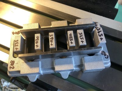
The first steps is to start with a flat base. The supplied casting is oversize and needs machining in many areas but some areas will not be touched.These are areas where nothing is fastened to them, i.e. the parts that are seen in the finished model.

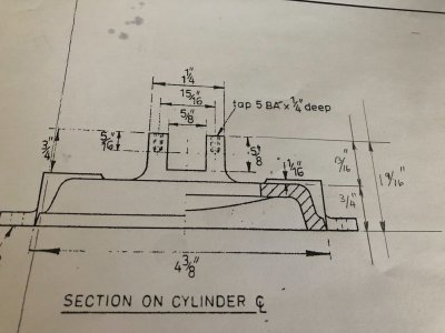
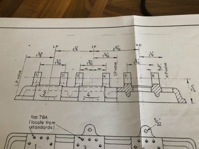
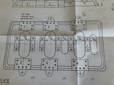
The drawings of the baseplate. Note the dimensions I have added in pencil just by doing calculations from the info given but these are ones I will work to establishing feels of the horizontal machined faces.

IMG_2734.jpgIMG_2735.jpgIMG_2736.jpg

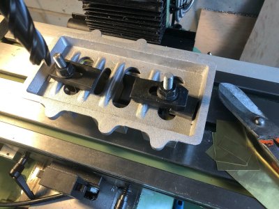
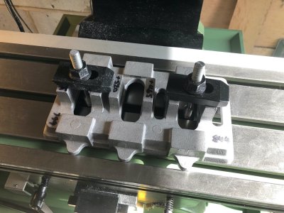
I am going to start machining the underside of the base flat on the mill. The cast surface which will be visible between the columns shall be my guide. There is a small step to the face the columns bolt to so this ideally should be consistent after completing all milling for the sake of appearance.Shown below is where the Parallels will touch the casting when inverted to set this true to the mill table. For those who don't know, Parallels come in a set of differing widths and you get two of each size. They are precision ground to ensure accuracy

IMG_2737.jpg

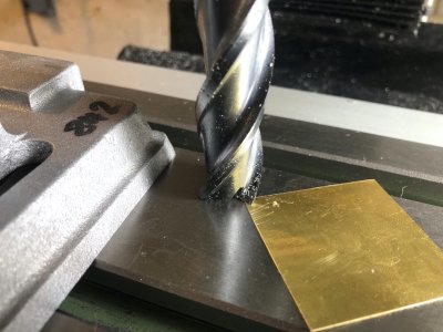
With the casting sat on the mill there was some rock corner to corner. The casting is a rough finish and not dimensionally perfect. I placed pieces of brass shim between the parallels and casting on two opposite corners to stop the casting rocking. This is important, the casting is Aluminium and I am sure the clamps would be capable of twisting the casting true, however when machined and released the bottom would not be flat.

The casting shimmed and clamped tight down
IMG_2738.jpg

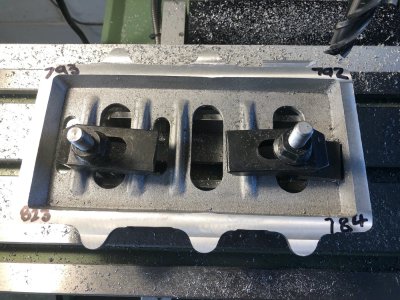
A fine cuts were taken until the mill removed all the rough face. The numbers on the corners are the thickness at each corner in thousands of an inch. I am chasing 750 Thou, 3/4 of a inch.
Looking at these numbers it is clear these rough cast corners are not in a true flat plane to one another.


IMG_2739.jpg

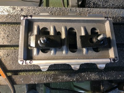
I added further packing to try and reach a happy medium and this is the result of subsequent passes with the mill after adjustment.

IMG_2740.jpg

Note one corner is 7 Thou less than the drawing but this is about as good as I can get with this. Key is knowing when to stop, I know I cannot better this with this casting.

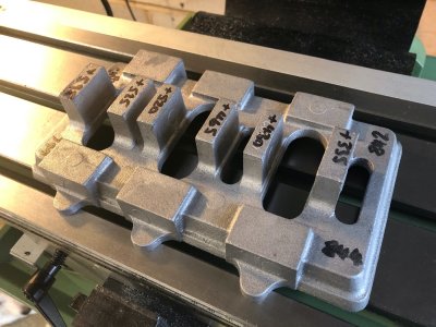
The casting removed from the clamps and all is good, it is perfectly flat and looks correct visually. This is purely cosmetic, it is the next stages when dimensions start to really matter. I do now have a solid flat datum to work from and this casting can now be further processes clamped right way up flat down to the mill table.

IMG_2741.jpg
 
What a wonderful project. This I will follow with great interest. Since I made my two cylinder Marcher engine using Reeves castings ( https://shipsofscale.com/sosforums/...launch-built-in-1877-in-warkaus-finland.3126/ ) I have wanted to build a triple compound one. Perhaps now I have courage enough to start the build.

Hi Moxis

It was a toss up between this and the Stuart triple. This one won for me as it is a model of a larger engine and however much I like the looks of the Stuart, this one just has that bit more IMHO
 
Hello Nigel!
Good start on your trip to mechanical greatness.
I have an uncle with machining background and I wanted to learn about the trade but sadly is a bit far from my place .
So I will learn a lot from this build !
Kind regards, Daniel
 
Hi Moxis

It was a toss up between this and the Stuart triple. This one won for me as it is a model of a larger engine and however much I like the looks of the Stuart, this one just has that bit more IMHO
Hi Nigel, until today I thought that the Stuart would be the one and only available. But now I learned about the Bolton as well. I wonder if the drawings & set of castings are sold by Reeves?
 
Bo
Hi Nigel, until today I thought that the Stuart would be the one and only available. But now I learned about the Bolton as well. I wonder if the drawings & set of castings are sold by Reeves?

Both castings and drawings currently avaiable from Reeves. I bought them when they had a sale on and at that time were cheaper than the Stuart, currently both are about the same
 
Bolton Part two

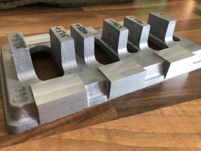
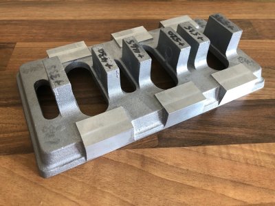
The next step is to mill the pads down the columns sit on to the correct height.

With the casting clamped to the table, I first touched the mill down to the table then used some 10 Thou shim brass as a feeler gauger to set the cutter 10 thou above the table

IMG_2743.jpgIMG_2744.jpg

The Z axis on the DRO is set to zero in this position.

IMG_2745.jpg

The cutter is then moved to touch one of the pads to see how much material is to remove. The target height is 13/16" which equals 0.8125". Allowing for the ten thou gap between cutter and bed, this tells me I have approx 120 thou of material to remove

IMG_2747.jpg

The six pads were milled to the correct height in gradual passes until the target dimension was reached.

Apologies now I did not take pictures of the next step. The casting was packed up on the mill bed so I could mill the sides. I milled off the ears for the fixing bolts for the base and reduced the overall width of the complete casting to the 4 3/8" specified on the drawing. You will notice the milled sides just graze the point of the bevel relief.

I will be making a full bed from Aluminium for this engine to sit on which will include the Propeller shaft thrust bearing. This supplied baseplate will become integral with this frame.

IMG_2754.jpgIMG_2755.jpgIMG_2756.jpg

IMG_2746.jpg
 
Well it has been raining all weekend but it wasn't that that has stopped play.

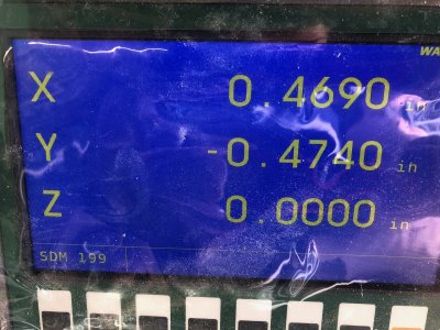
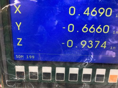
My DRO scale on the x axis is shot. I set up the base to start milling the main bearing housings and noticed the figures on the screen weren't changing.Looking at my previous post you will notice the same figure in both pictures of the screen for the x axis despite the table being in different positions.

I have stripped it down and the reader head has been crushed. I did run the power feed traverse on the table right across to the left when deciding on the position for my new lathe and there was a crunch but I didn't know what it was, now I do! There is a limit stop on the table so will have to investigate this is adjusted correctly once I replace the scale.

Oh well will order a replacement, hopefully Warco have one in stock
 
The replacement scale for the mill has been dispatched today so I should be back in business fairly soon :)

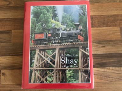
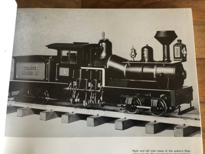
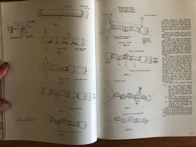
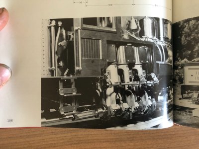
The book I have been talking about for the final part of the " bucket list trilogy" arrived last Friday.

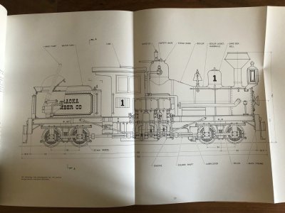
The book includes not only dimensioned drawings for every component to build the Locomotive but also comes with instructions of how to build them in great detail. Some of the drawings are a little small but Kozo had to condense them to fit in the book some how.

A few pictures to give you an idea and yes the last picture is a model not the prototype. It is the exposed vertical three cylinder steam engine and transmission that stirs my interest.

Apologies for my nails, just got back from work:rolleyes:

IMG_2760.jpgIMG_2761.jpgIMG_2762.jpgIMG_2763.jpgIMG_2764.jpg
 
A Shay! If you have not already gone so, you need to add a trip to West Virginia, or as they say, West by Golly Virginia, to your bucket list. The Cass Scenic Railroad there operates Shay Locomotives to haul passengers up a mountain. The trip includes an 11 percent grade. The railroad was built by a lumber company.

Roger
I doubt I will ever make it to West Virginia Roger, but I shall search for it on Youtube :)
 
When we lived in nearby Southeastern Ohio, we made a couple of trips there. At that time it was surprisingly relaxed. One could wander into the shop where they maintained these engines and could get up close where they watered and fueled them. It is now a West Virginia State Park so I assume that things are more formal now.

Roger
 
Bolton part three.

With the replacement scale now fitted to the mill, I am back in business:)

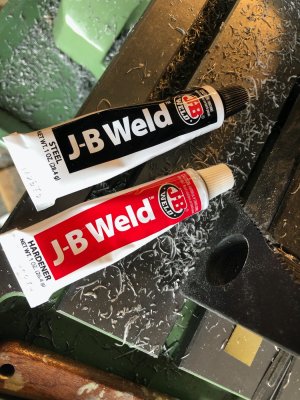
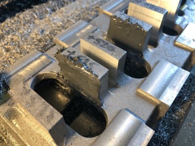
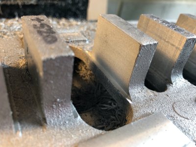
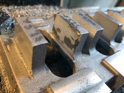
With the base clamped and carefully lined up with the mill table I have now started milling the ends square of the main bearing housings.Bertinat mentions there is in error in the castings with one housing cast out of position. He used the AJ Winter castings whereas mine are from Reeves. However there is still an error and I will show you how I fix it. I did try and shift the machined housing positions to minimise error. This means two faces need material adding. This is built up using JB weld. For this the original red and black tubes is the one to buy. This is the original slow setting metal impregnated epoxy version and can indeed be machined just like metal. I have seen some very talented model engineers build multipiece engine blocks using this stuff as an adhesive.It really is that good..

Milling the end faces of the housings

IMG_2769.jpgIMG_2770.jpg

The JB weld and application to the two offending faces

IMG_2775.jpgIMG_2771.jpg

The first face milled after leaving overnight to fully harden. The layer of JB weld is only 7 Thou thick on this area

IMG_2773.jpg

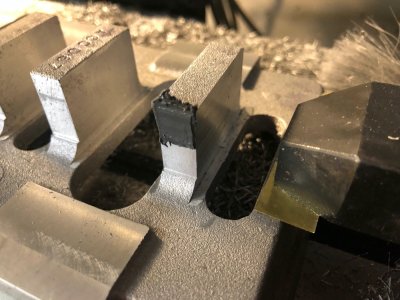
The second housing was milled but needs a second layer of JB, note the low spots. This layer is still relatively thin and is well clear of the tapped holes that will be added to secure the bearing caps

IMG_2774-1.jpg

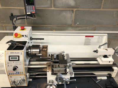
Finally my new lathe in it's home with main cylinder block in the 4 Jaw chuck. More on this in my next update

IMG_2776.jpg
 
Bolton part four

Plenty of pictures, as I have power feed on both mill and lathe, both machines have been running at the same time for some operations

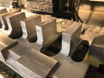
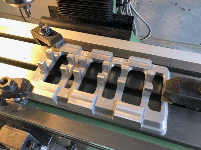
Firstly, the baseplate milling on the top face is now complete, I have deviated from the drawings somewhat with the cut outs.This base gets some flack for not being true to practice for a marine engine, so the various changes I am making hopefully will make it more "marine" than mantlepiece.

I did have to add a small amount of JB weld to the outside of one bearing housing as the casting was a little small in this area.

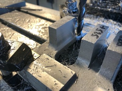
The base is now ready for drilling and tapping some 61 holes to take the bearing cap fixings and studs to hold the column bases. Positioning will be done via the DRO

IMG_2778.jpgIMG_2779.jpgIMG_2792.jpgIMG_2793.jpgIMG_2794.jpg

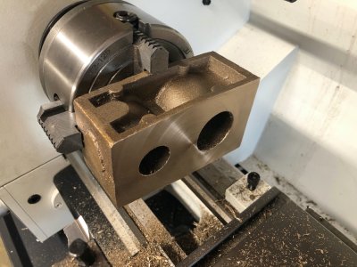
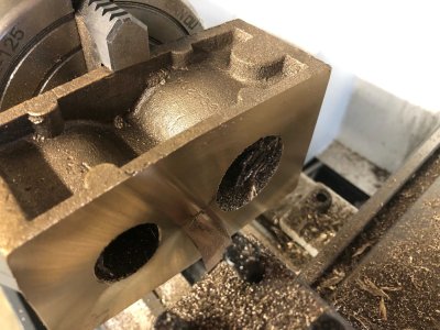
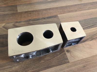
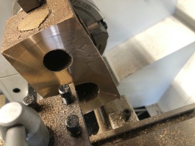
I have also been turning both cylinder blocks on the lathe to face off the top and bottom of the castings to bring the total thickness to 2 inches. These are now ready to go onto the mill for the next operations once the base is done.

IMG_2777.jpgIMG_2787.jpgIMG_2796.jpg

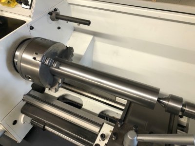
Finally, I had bought a billet of EN8 steel to make the crankshaft a good while ago. I gave up on this at the time as my small lathe was far too flexible and not powerful enough to work this medium carbon steel.
My new machine copes with this material in it's stride and the billet has been turned to the maximum diameter of the crank.

IMG_2795.jpg

IMG_2786.jpg
 
Bolton part five

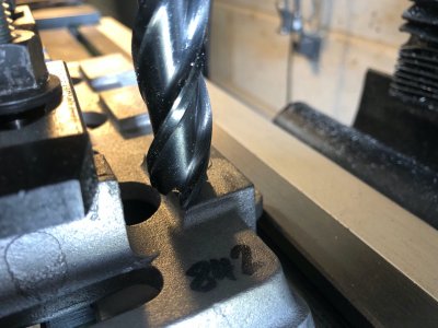
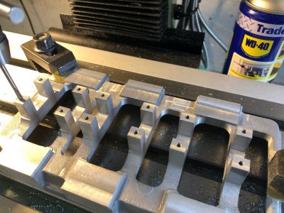
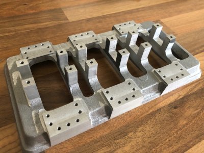
After much brain ache working out my coordinates for the plethora of holes I have drilled and tapped all the holes. I used the centreline of the crank and centre of the bearing housing at the flywheel end.
Working like this means I have no accumulative errors in the hole positioning which is essential to ensure the columns are true in relation to the crank journals.

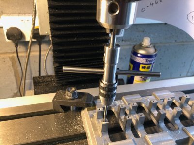
When tapping the holes I used a centring tap wrench, this has a sliding rod running inside which in turn is fitted in the chuck of the drill. You still tap manually but this tool ensures all threads are cut square to the base.

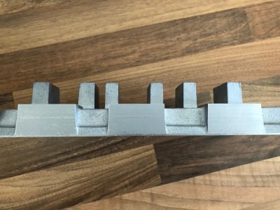
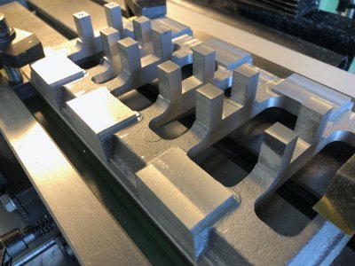
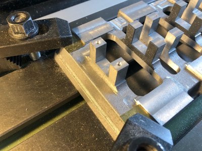
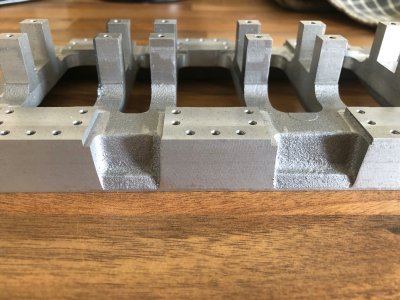
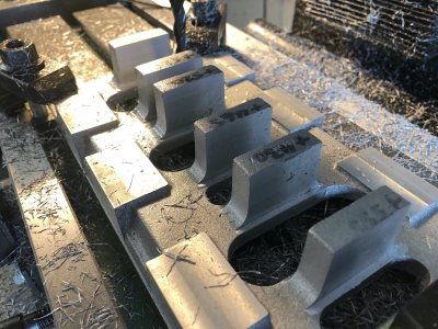
There is quite a bit of Dremel work to do. I milled the exact profile of the column feet on the base. This will all need blending in along with the radiuses at the base of the bearing housings. I may yet add Aluminum webs to these housings bonded with JB weld.

The side profile of the feet need continuing on the side of the base. I am currently thinking how to remove some of the material on the mill with the base canted over before finishing with a carbide burr.

IMG_2797.jpgIMG_2798.jpgIMG_2799.jpgIMG_2800.jpg
 
Bolton part five

After much brain ache working out my coordinates for the plethora of holes I have drilled and tapped all the holes. I used the centreline of the crank and centre of the bearing housing at the flywheel end.
Working like this means I have no accumulative errors in the hole positioning which is essential to ensure the columns are true in relation to the crank journals.

When tapping the holes I used a centring tap wrench, this has a sliding rod running inside which in turn is fitted in the chuck of the drill. You still tap manually but this tool ensures all threads are cut square to the base.

There is quite a bit of Dremel work to do. I milled the exact profile of the column feet on the base. This will all need blending in along with the radiuses at the base of the bearing housings. I may yet add Aluminum webs to these housings bonded with JB weld.

The side profile of the feet need continuing on the side of the base. I am currently thinking how to remove some of the material on the mill with the base canted over before finishing with a carbide burr.

View attachment 535850View attachment 535851View attachment 535852View attachment 535853
A master at his craft...
 
Back
Top