• LUCZORAMA SHIPWRECK SCAVENGER HUNT GIVEAWAY. 4 Weeks of Fun • 1 Legendary Prize ((OcCre’s Fram Ship)) • Global Crew Welcome!
    **VIEW THREAD HERE**

O.B. Bolton Marine Triple Expansion Steam Engine using castings by AJ Reeves, drawings by John Bertinat

After towing and riving on Wednesday and having been at work this morning I just wanted to get in the garage and make some chips, so here is part one of my build.

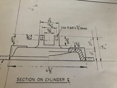
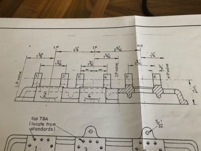
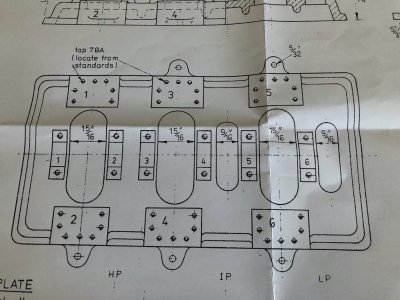
I will show the drawings of the relevant part so everyone understands what I am doing.

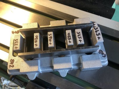
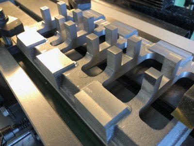
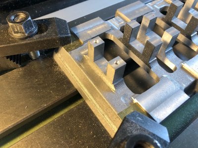
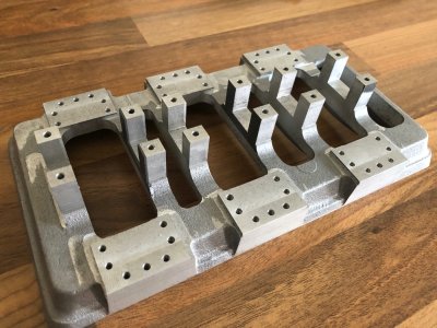
The first steps is to start with a flat base. The supplied casting is oversize and needs machining in many areas but some areas will not be touched.These are areas where nothing is fastened to them, i.e. the parts that are seen in the finished model.

The drawings of the baseplate. Note the dimensions I have added in pencil just by doing calculations from the info given but these are ones I will work to establishing feels of the horizontal machined faces.

IMG_2734.jpgIMG_2735.jpgIMG_2736.jpg

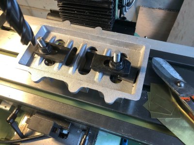
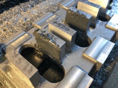
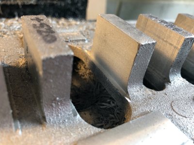
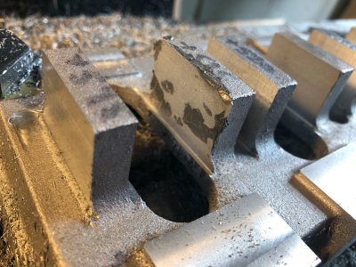
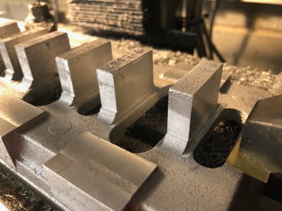
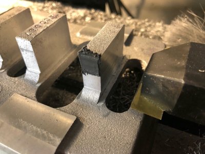
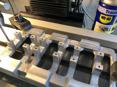
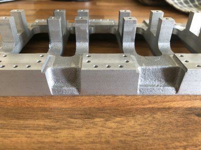
I am going to start machining the underside of the base flat on the mill. The cast surface which will be visible between the columns shall be my guide. There is a small step to the face the columns bolt to so this ideally should be consistent after completing all milling for the sake of appearance.Shown below is where the Parallels will touch the casting when inverted to set this true to the mill table. For those who don't know, Parallels come in a set of differing widths and you get two of each size. They are precision ground to ensure accuracy

IMG_2737.jpg

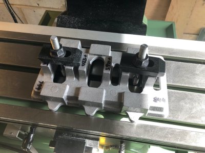
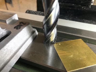
With the casting sat on the mill there was some rock corner to corner. The casting is a rough finish and not dimensionally perfect. I placed pieces of brass shim between the parallels and casting on two opposite corners to stop the casting rocking. This is important, the casting is Aluminium and I am sure the clamps would be capable of twisting the casting true, however when machined and released the bottom would not be flat.

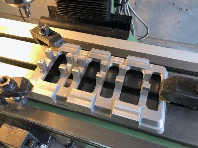
The casting shimmed and clamped tight down
IMG_2738.jpg

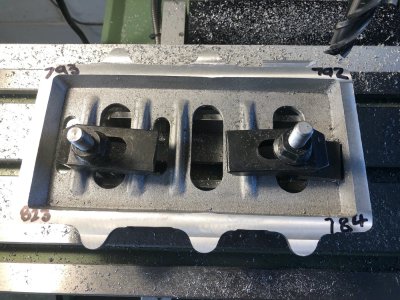
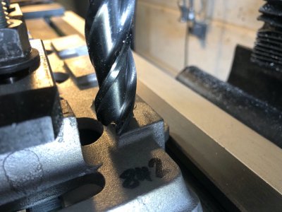
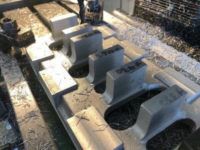
A fine cuts were taken until the mill removed all the rough face. The numbers on the corners are the thickness at each corner in thousands of an inch. I am chasing 750 Thou, 3/4 of a inch.
Looking at these numbers it is clear these rough cast corners are not in a true flat plane to one another.


IMG_2739.jpg

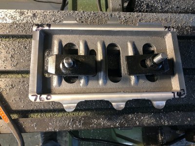
I added further packing to try and reach a happy medium and this is the result of subsequent passes with the mill after adjustment.

IMG_2740.jpg

Note one corner is 7 Thou less than the drawing but this is about as good as I can get with this. Key is knowing when to stop, I know I cannot better this with this casting.

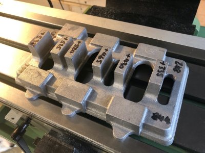
The casting removed from the clamps and all is good, it is perfectly flat and looks correct visually. This is purely cosmetic, it is the next stages when dimensions start to really matter. I do now have a solid flat datum to work from and this casting can now be further processes clamped right way up flat down to the mill table.

IMG_2741.jpg
 
What a wonderful project. This I will follow with great interest. Since I made my two cylinder Marcher engine using Reeves castings ( https://shipsofscale.com/sosforums/...launch-built-in-1877-in-warkaus-finland.3126/ ) I have wanted to build a triple compound one. Perhaps now I have courage enough to start the build.

Hi Moxis

It was a toss up between this and the Stuart triple. This one won for me as it is a model of a larger engine and however much I like the looks of the Stuart, this one just has that bit more IMHO
 
Hello Nigel!
Good start on your trip to mechanical greatness.
I have an uncle with machining background and I wanted to learn about the trade but sadly is a bit far from my place .
So I will learn a lot from this build !
Kind regards, Daniel
 
Hi Moxis

It was a toss up between this and the Stuart triple. This one won for me as it is a model of a larger engine and however much I like the looks of the Stuart, this one just has that bit more IMHO
Hi Nigel, until today I thought that the Stuart would be the one and only available. But now I learned about the Bolton as well. I wonder if the drawings & set of castings are sold by Reeves?
 
Bo
Hi Nigel, until today I thought that the Stuart would be the one and only available. But now I learned about the Bolton as well. I wonder if the drawings & set of castings are sold by Reeves?

Both castings and drawings currently avaiable from Reeves. I bought them when they had a sale on and at that time were cheaper than the Stuart, currently both are about the same
 
Bolton Part two

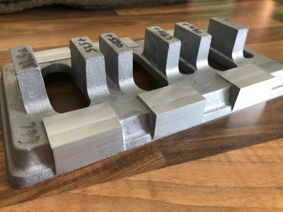
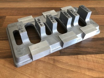
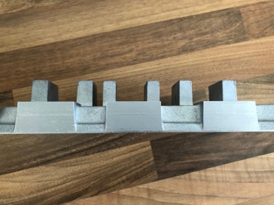
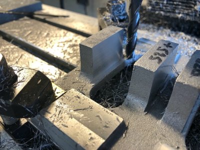
The next step is to mill the pads down the columns sit on to the correct height.

With the casting clamped to the table, I first touched the mill down to the table then used some 10 Thou shim brass as a feeler gauger to set the cutter 10 thou above the table

IMG_2743.jpgIMG_2744.jpg

The Z axis on the DRO is set to zero in this position.

IMG_2745.jpg

The cutter is then moved to touch one of the pads to see how much material is to remove. The target height is 13/16" which equals 0.8125". Allowing for the ten thou gap between cutter and bed, this tells me I have approx 120 thou of material to remove

IMG_2747.jpg

The six pads were milled to the correct height in gradual passes until the target dimension was reached.

Apologies now I did not take pictures of the next step. The casting was packed up on the mill bed so I could mill the sides. I milled off the ears for the fixing bolts for the base and reduced the overall width of the complete casting to the 4 3/8" specified on the drawing. You will notice the milled sides just graze the point of the bevel relief.

I will be making a full bed from Aluminium for this engine to sit on which will include the Propeller shaft thrust bearing. This supplied baseplate will become integral with this frame.

IMG_2754.jpgIMG_2755.jpgIMG_2756.jpg

IMG_2746.jpg
 
Well it has been raining all weekend but it wasn't that that has stopped play.

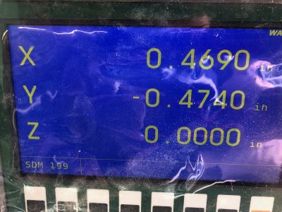
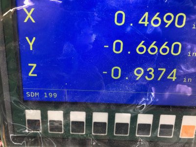
My DRO scale on the x axis is shot. I set up the base to start milling the main bearing housings and noticed the figures on the screen weren't changing.Looking at my previous post you will notice the same figure in both pictures of the screen for the x axis despite the table being in different positions.

I have stripped it down and the reader head has been crushed. I did run the power feed traverse on the table right across to the left when deciding on the position for my new lathe and there was a crunch but I didn't know what it was, now I do! There is a limit stop on the table so will have to investigate this is adjusted correctly once I replace the scale.

Oh well will order a replacement, hopefully Warco have one in stock
 
Back
Top