• Ships of Scale has incorportated an extra level of security when you log In. Please follow on-screen prompts to acknowledge that you are not a robot via a "Check Box" or a "Pictorial Check Box Puzzle". This is needed due to higher level of AI Activity Security.
  • SUBSCRIBE TO SHIPS IN SCALE TODAY!

    The beloved Ships in Scale Magazine is back and charting a new course for 2026!
    Discover new skills, new techniques, and new inspirations in every issue.

    NOTE THAT OUR NEXT ISSUE WILL BE July/August 2026
  • Win a Free Custom Engraved Brass Coin!!!
    As a way to introduce our brass coins to the community, we will raffle off a free coin during the month of August. Follow link ABOVE for instructions for entering.

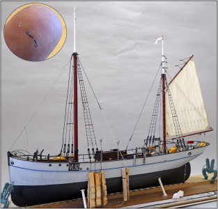
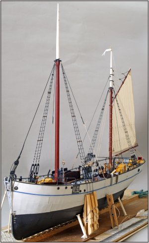
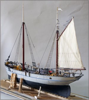
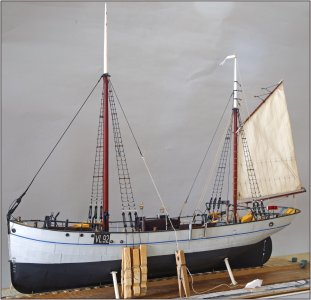
BALDER, Vlaardingen Herring Lugger from 1912, scratch build scale 1:50 Plate-On-Frame

Due to the twisting of the mast and the placement of the shrouds, a few different small angles occur.

I seemed to recall that you said (quite some time ago) that the mast was twisted. Now, my mind is a steel trap, however the hinges are getting a bit rusty with age, so I went back a few pages on your log to look at some images. It appears that the mast bunk is offset to port, but perhaps it is simply an optical illusion due to the way you constructed it in two halves. If indeed the mast is on centerline, then my previous theory goes out the window.

Regardless, she is coming along beautifully Peter. You are truly a master.
 
In real life it is not always that perfect then on the models of us. Lol, I think one side is done on monday and the other side on friday.
 
I seemed to recall that you said (quite some time ago) that the mast was twisted. Now, my mind is a steel trap, however the hinges are getting a bit rusty with age, so I went back a few pages on your log to look at some images. It appears that the mast bunk is offset to port, but perhaps it is simply an optical illusion due to the way you constructed it in two halves. If indeed the mast is on centerline, then my previous theory goes out the window.

Regardless, she is coming along beautifully Peter. You are truly a master.

Hi Russ.
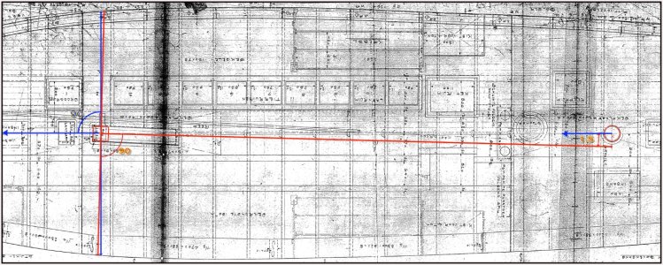
I have drawn some lines in this top view to clarify a few things. But you have correctly recognized some very specific items:
1188 Offset.jpg
-On the Balder, the mainmast is rotated 1.5 degrees clockwise to fall alongside the mizzenmast; see the red arrow/mast axis line from the center of the mainmast. In the drawing, the 'kossing'/mast bunk is rotated almost 2.5 degrees, but that has been adjusted for the Balder.
-From that center, both forward deadeyes/shrouds are perpendicular to that red line. See the red double arrow with the red 90° indication.
-I have indicated the longitudinal axis of the hull for the mainmast and mizzenmast with some blue arrows.
-A length shift would occur between the starboard and port shrouds when the lowering of the mast, if they were installed perpendicular to the longitudinal direction. See the blue double arrow from the center of the mainmast and the bleu 90° indication. But that extension would also be compensated with the lanyards that are already being detached anyway to extend the front one and pull in the rear one.
Regards, Peter
 
Hi Russ.
I have drawn some lines in this top view to clarify a few things. But you have correctly recognized some very specific items:
View attachment 625607
-On the Balder, the mainmast is rotated 1.5 degrees clockwise to fall alongside the mizzenmast; see the red arrow/mast axis line from the center of the mainmast. In the drawing, the 'kossing'/mast bunk is rotated almost 2.5 degrees, but that has been adjusted for the Balder.
-From that center, both forward deadeyes/shrouds are perpendicular to that red line. See the red double arrow with the red 90° indication.
-I have indicated the longitudinal axis of the hull for the mainmast and mizzenmast with some blue arrows.
-A length shift would occur between the starboard and port shrouds when the lowering of the mast, if they were installed perpendicular to the longitudinal direction. See the blue double arrow from the center of the mainmast and the bleu 90° indication. But that extension would also be compensated with the lanyards that are already being detached anyway to extend the front one and pull in the rear one.
Regards, Peter

Thank you for the drawing and great explanation. Now that it is obvious that the mainmast is attached along the longitudinal centerline of the vessel, I can find no logical reason for one set of shrouds to have one fewer ratlines than the other.

Perhaps Hendrik tied the lines on the starboard side and Johan tied them on port, except that Johan lost a finger in a terrible Fierljeppen accident and therefore has trouble counting. :cool:
 
In real life it is not always that perfect then on the models of us. Lol, I think one side is done on monday and the other side on friday.
Perhaps Hendrik tied the lines on the starboard side and Johan tied them on port, except that Johan lost a finger in a terrible Fierljeppen accident and therefore has trouble counting.
That’s it: Hendrik did the starboard side on Monday and Johan the port side on Friday …..ROTF
PS: it’s not the Johan @RDN1954, valued member of the D.B.B.S !!!! :)
Regards, Peter
 
Last edited:
And then the rigging on this side is finished as well:
1189 weeflijnen.jpg
Here too, I could no longer secure the small top lines in the middle with a clove hitch. So I secured them with a small piece of Serafil.

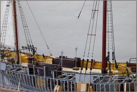
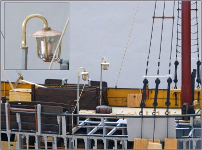
In between, I also installed both deck lights on the deck at the front of the keven/fish holds.
1190 Lampen.jpg
No, they cannot light .....;)

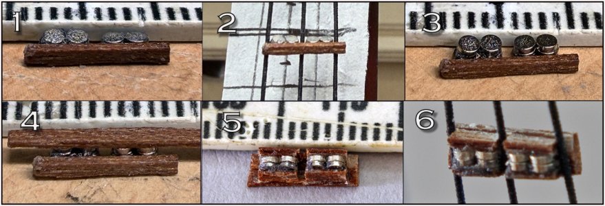
On page 127 #2521 I had already shown the divisible spreader bars with the magnets on the mizzen. Here are the steps taken to get the 2x4 neodymium magnets of 1.5 x 0.5 mm into place:
1191 Magnets.jpg
In photo 1, I forgot to capture the starting point. I first placed the first 4 magnets next to each other on a scalpel blade. They jump in all directions due to the polarity. After some help, they eventually lie next to each other. When placing the 2nd row in step 3, they initially wanted to find their own spot again, but with some firm help here too, they found their position.
While making the cutouts in the upper and lower bar for the shrouds, one of the 2 parts slipped from my fingers. After searching for a long time, I found the part on the inside of a pair of tweezers. That had already happened to me with the mizzen magnets.;)
Now tie both parts separately on the shrouds. The shrouds will be cut later.
Regards, Peter
 
And then the rigging on this side is finished as well:
View attachment 626812
Here too, I could no longer secure the small top lines in the middle with a clove hitch. So I secured them with a small piece of Serafil.

In between, I also installed both deck lights on the deck at the front of the keven/fish holds.
View attachment 626813
No, they cannot light .....;)

On page 127 #2521 I had already shown the divisible spreader bars with the magnets on the mizzen. Here are the steps taken to get the 2x4 neodymium magnets of 1.5 x 0.5 mm into place:
View attachment 626814
In photo 1, I forgot to capture the starting point. I first placed the first 4 magnets next to each other on a scalpel blade. They jump in all directions due to the polarity. After some help, they eventually lie next to each other. When placing the 2nd row in step 3, they initially wanted to find their own spot again, but with some firm help here too, they found their position.
While making the cutouts in the upper and lower bar for the shrouds, one of the 2 parts slipped from my fingers. After searching for a long time, I found the part on the inside of a pair of tweezers. That had already happened to me with the mizzen magnets.;)
Now tie both parts separately on the shrouds. The shrouds will be cut later.
Regards, Peter
Ratlines hang perfectly, Peter. And I like the addition of Victorian era lighting. It must have been eerie dark on the ship at night.
 
And I like the addition of Victorian era lighting. It must have been eerie dark on the ship at night.
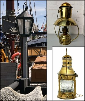
I am not yet satisfied with the lamps myself.
1192 Lamps.jpg
On the left is the imitation lamp that is on the Balder. That was partly the reason for my current choice. And it can be found in approximately the right scale.
However, my preference is for one of the two on the right in the picture. For the time being, it cannot be found in scale. Maybe I should get out the magic box of parts after all.....
Regards, Peter
 
Actually wasn't happy with the lamps at all. I took a piece of copper foil and cut out 2 circles, which I forced until they had a bulge.
1193 Lamps.jpg
With the glass from the first lamps, some 0.8 and 0.5 copper wire and some small rings, this was the result. It was a fiddling job with the tweezers again.
That looks much better IMHO ......
Regards, Peter
 
Actually wasn't happy with the lamps at all. I took a piece of copper foil and cut out 2 circles, which I forced until they had a bulge.
View attachment 626922
With the glass from the first lamps, some 0.8 and 0.5 copper wire and some small rings, this was the result. It was a fiddling job with the tweezers again.
That looks much better IMHO ......
Regards, Peter
Yup, that looks much more period appropriate.
 
Ratlines hang perfectly, Peter. And I like the addition of Victorian era lighting. It must have been eerie dark on the ship at night.
I agree with the boys. I assumed the Victorian lamps were period and application correct - these new lamps look more nautical...
Sorry that I missed your first post, Paul. My first impression was that I could use them. But after some time there was a ….. whaa ….
With some input on the Dutch forum gives me the push to fiddle the new ones.
Indeed: mire nautical.
Regards, Peter
 
After nearly 3 weeks of making ratlines, I can close this chapter on the mainmast as well:
1196 Weeflijnen.jpg
46x first punch 2x right with the small syringe needle in a 0.25 mm thread to make the 1st imitation splice, then measure the length and hit the right 2x again at the correct distance for the 2nd splice ..........:rolleyes: not to mention the number of missed stitches ........Speechless and cutting the wrong end off ....... Sick
Then first tie the left eye to the shroud rope, use the remaining end for a clove hitch around the middle shroud rope and then secure the right eye. And that remaining piece keeps getting shorter and shorter....... the tips of my smallest tweezers could just barely make the pull-through .......
I don't know if I will do this ones more ....

But I am still quite happy with the result:
1194 Weeflijnen.jpg
Fortunately not a three-masted model .......;)
1195 Weeflijnen.jpg
Before the mast comes off again to be rigged further in the vice, first measure the size for the mainsail and the jib. Then first make a paper version and check if everything is to my liking.
Regards, Peter
 
Last edited:
It looks great Peter ... but ... wait ... both sides have the same number of ratlines. Didn't we already have this discussion? ;)

Seriously, it is a work of art!
 
Back
Top