• Ships of Scale has incorportated an extra level of security when you log In. Please follow on-screen prompts to acknowledge that you are not a robot via a "Check Box" or a "Pictorial Check Box Puzzle". This is needed due to higher level of AI Activity Security.
  • SUBSCRIBE TO SHIPS IN SCALE TODAY!

    The beloved Ships in Scale Magazine is back and charting a new course for 2026!
    Discover new skills, new techniques, and new inspirations in every issue.

    NOTE THAT OUR NEXT ISSUE WILL BE July/August 2026
  • Win a Free Custom Engraved Brass Coin!!!
    As a way to introduce our brass coins to the community, we will raffle off a free coin during the month of August. Follow link ABOVE for instructions for entering.

HMS Alert [1777] 1:48 POF by serikoff. (Two hulls: skeleton and fully rigged)

Chapter 26. On the Decks (Part 4)

3/
Pumps.


I've previously demonstrated the process of making all metal parts by electroplating 3D-printed plastic parts with copper.
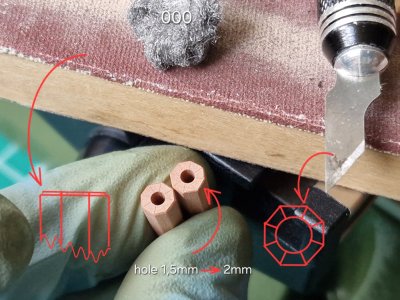
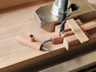
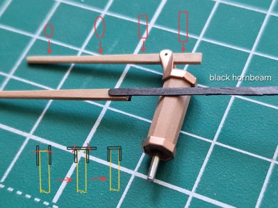
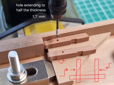
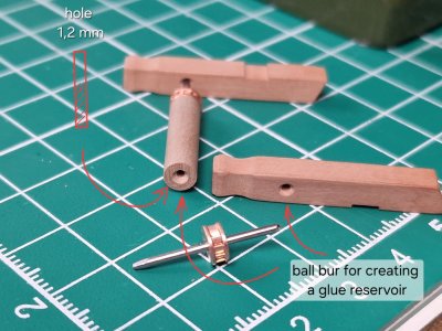
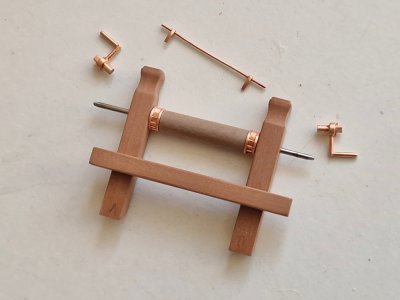
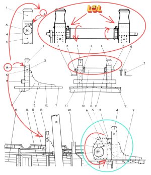
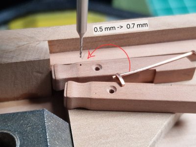
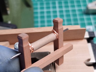
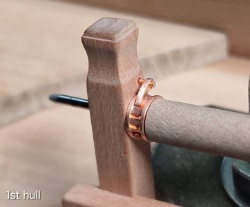
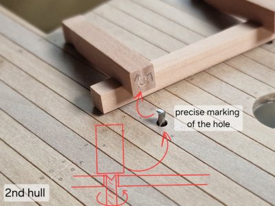
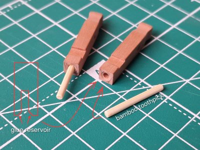
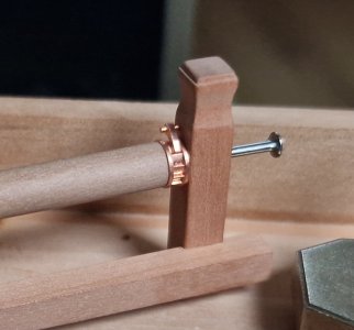
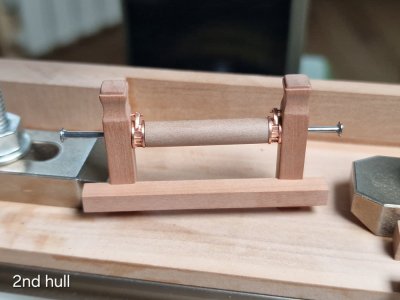
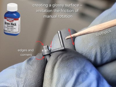
Now I'm processing, polishing, blackening, and making wooden components for them. All the work with the wooden blanks is described in the illustrations. I've emphasized all the key points.

View attachment 631980

View attachment 631983

View attachment 631984

View attachment 631985

View attachment 631986

View attachment 631988

View attachment 631989

View attachment 631990

View attachment 631991

View attachment 631992

View attachment 631994

View attachment 631995

View attachment 631996

View attachment 631997

View attachment 631998

View attachment 631999

View attachment 632000

View attachment 632001

View attachment 632002

View attachment 632003
To be continued...
Nice work, Sergey. ‘It’s all in the details!’
Regards, Peter
 
Amazing work, as always ! Thank you again !
Your attention to detail is amazing !
Wunderbare Arbeit. Fantastische Darstellung der einzelnen Schritte. Anschaulich, Präzise und sehr verständlich. Beeindruckend ist die konstante und konsequente Detailliebe - und Umsetzung. Danke, dass Sie uns daran teilhaben lassen.
Nice work, Sergey. ‘It’s all in the details!’
Regards, Peter
Thank you so much, friends, for the kind words! It’s very motivating!


Friends, colleagues...

For anyone interested in how to turn a photograph into a 3D object — I’ve written a post in the relevant thread; prepare to be amazed...

at the link >>>

Gemini_Generated mesha 2.JPG
 
Last edited:
Chapter 26. On the Decks (Part 4)

4/
Pumps.
(continuation)

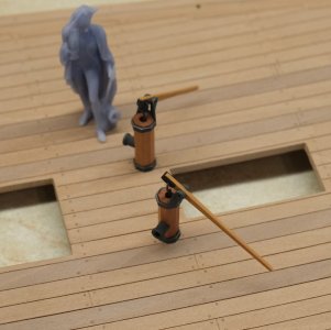
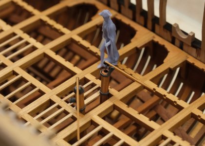
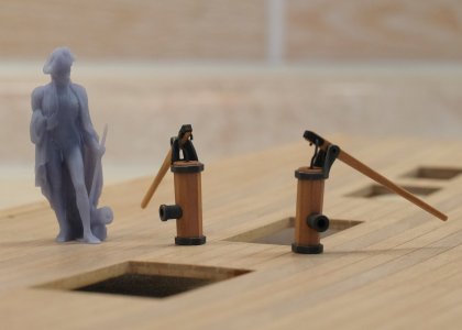
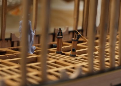
So, let's continue... I didn't expect the pumps to take up so much time, but the main thing is that I'm really pleased with the result. It's not quite finished yet—I still have the securing stage to go—but for now, it's 90% complete...

Alert 2911.jpg

Alert 2912.jpg

Alert 2913.jpg

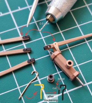
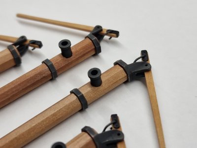
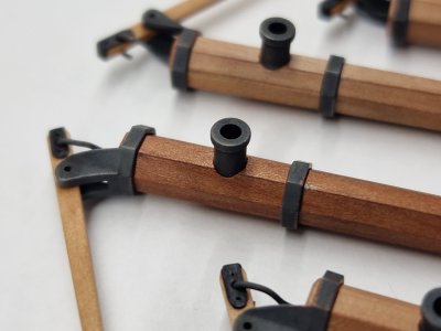
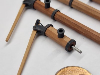
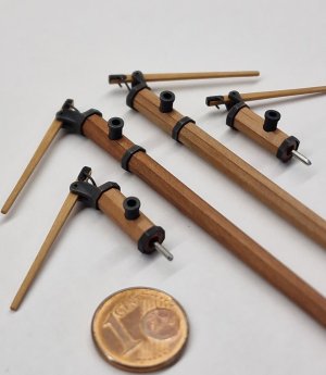
I frankly disliked the design Goodwin depicted in all his anatomical studies regarding the transition from the lever to the piston rod (the hook). That version appeared in another book as well, but I am more than certain it was merely a schematic representation; I highly doubt such a design would have functioned properly (though I could be mistaken). Instead, I followed a design I had seen in several sources—including museum pieces, though I no longer recall exactly which ones. The piston rod passed through the lever, and a reinforcing bracket was fitted around the lever to prevent chafing at that point. I liked that approach, so that is the one I used.

Alert 2914.jpg

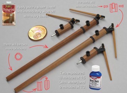
Before assembly, I coated the pear wood with pure Tung oil (I’m specifying this one last time; from now on, this is exactly how I’ll always do it). I dampen a paper towel (or occasionally a cloth), wipe the wood, and immediately wipe off the excess with a dry paper towel. I apply Danish oil the same way. Sometimes I might use a slightly damp brush if I can't reach into a recess, but I immediately wipe away the excess.

Alert 2915.JPG

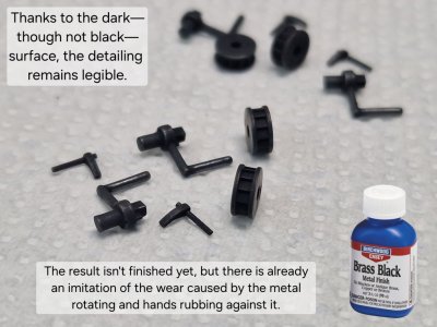
I treat the copper parts in the same standard way (I am specifying this one last time; the procedures remain unchanged from here on out). I work wearing nitrile gloves, so the copper parts aren't soiled with grease, and I don't need to degrease them. I dilute the BB solution 1:5 with plain water and perform the first exposure for 18–20 minutes. Then, I rinse the parts, let them air-dry for about 20 minutes, and use a very soft brush to sweep away the residue/film from the surface. Next, I perform a second exposure in a 1:3 BB-to-water solution for 9–10 minutes. After that, I rinse and let them air-dry again—this time for longer, 30 minutes or more. Once the film is lightly brushed off, the parts are ready to use. This method takes time, but the results are highly predictable. It produces a very dark graphite color—not pure black—with a durable, uniform coating that doesn't flake or crumble. Naturally, the finish remains vulnerable to scratches from hard objects, but that has always been the case. I don't specifically repair minor chips or scuffs; they add a natural look, and the dark copper exposed underneath mimics the rust on forged iron. For a museum-quality appearance, this is actually a plus.

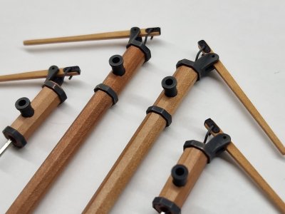
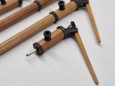
A few macro shots:

Alert 2916.jpg

Alert 2917.jpg

Alert 2918.jpg

Alert 2919.jpg

Alert 2920.jpg

Alert 2921.jpg

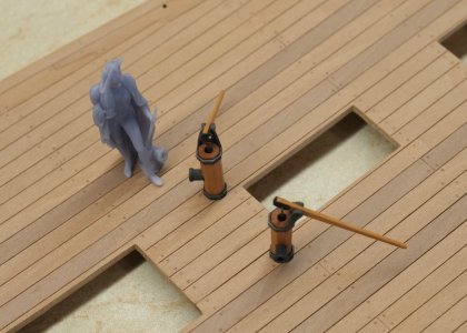
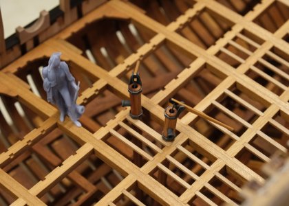
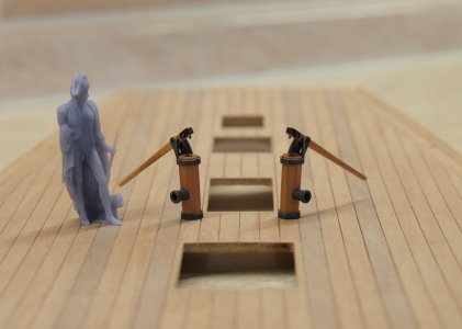
And here is how it will look on the model, under Nelson's watchful eye:

Alert 2922.JPG

Alert 2923.JPG

Alert 2924.JPG

Alert 2925.JPG

Alert 2926.JPG

Alert 2927.JPG

Alert 2928.JPG

Finally, the pumps are almost done... and I can move on to the next part—the flue.
 
Last edited:
Kapitel 26. An Deck (Teil 4)

4/
Pumps.


So, weiter geht's... Ich hatte nicht erwartet, dass die Pumpen so viel Zeit in Anspruch nehmen würden, aber Hauptsache ist, dass ich mit dem Ergebnis sehr zufrieden bin. Es ist noch nicht ganz fertig – die Befestigung steht noch aus –, aber im Moment ist es zu 90 % abgeschlossen.

View attachment 634082

View attachment 634083

View attachment 634084

Ehrlich gesagt missfiel mir Goodwins Darstellung des Übergangs vom Hebel zur Kolbenstange (dem Haken) in all seinen anatomischen Studien. Diese Version tauchte auch in einem anderen Buch auf, aber ich bin mir ziemlich sicher, dass es sich dabei lediglich um eine schematische Darstellung handelte; ich bezweifle stark, dass eine solche Konstruktion ordnungsgemäß funktioniert hätte (obwohl ich mich irren könnte). Stattdessen folgte ich einer Konstruktion, die ich in verschiedenen Quellen gesehen hatte – darunter auch Museumsstücke, an die ich mich aber nicht mehr genau erinnere. Die Kolbenstange verlief durch den Hebel, und eine Verstärkungsstrebe war um den Hebel angebracht, um ein Scheuern an dieser Stelle zu verhindern. Mir gefiel dieser Ansatz, also habe ich ihn verwendet.

View attachment 634085

Vor dem Zusammenbau habe ich das Birnbaumholz mit reinem Tungöl behandelt (ich erwähne das hier zum letzten Mal; von nun an werde ich es immer so machen). Ich befeuchte ein Papiertuch (oder gelegentlich ein Tuch), wische das Holz damit ab und entferne sofort den Überschuss mit einem trockenen Papiertuch. Dänisches Öl trage ich auf die gleiche Weise auf. Manchmal verwende ich einen leicht angefeuchteten Pinsel, wenn ich eine Vertiefung nicht erreiche, entferne aber auch hier sofort den Überschuss.

View attachment 634086

Die Kupferteile behandle ich nach demselben Standardverfahren (diese Vorgehensweise wird hier ein letztes Mal erwähnt; die weiteren Schritte bleiben unverändert). Ich trage Nitrilhandschuhe, damit die Kupferteile nicht mit Fett verschmutzt werden und ich sie nicht entfetten muss. Die BB-Lösung verdünne ich 1:5 mit Wasser und lasse sie 18–20 Minuten einwirken. Anschließend spüle ich die Teile ab, lasse sie etwa 20 Minuten an der Luft trocknen und entferne die Rückstände/den Film mit einem sehr weichen Pinsel. Danach bearbeite ich die Teile ein zweites Mal mit einer 1:3-BB-Wasser-Lösung für 9–10 Minuten. Anschließend spüle ich sie erneut ab und lasse sie wieder an der Luft trocknen – diesmal länger, 30 Minuten oder mehr. Sobald der Film leicht abgebürstet ist, sind die Teile einsatzbereit. Diese Methode ist zwar zeitaufwendig, liefert aber sehr zuverlässige Ergebnisse. Sie erzeugt eine sehr dunkle Graphitfarbe – kein reines Schwarz – mit einer haltbaren, gleichmäßigen Beschichtung, die nicht abblättert oder bröckelt. Natürlich bleibt die Oberfläche anfällig für Kratzer durch harte Gegenstände, aber das war schon immer so. Kleinere Absplitterungen oder Schrammen repariere ich nicht gezielt; sie verleihen dem Ganzen einen natürlichen Look, und das darunterliegende dunkle Kupfer imitiert den Rost auf Schmiedeeisen. Für eine museale Optik ist das sogar ein Vorteil.

Ein paar Makroaufnahmen:

View attachment 634087

View attachment 634088

View attachment 634089

View attachment 634090

View attachment 634091

View attachment 634092

Und so wird es am Modell unter Nelsons wachsamen Augen aussehen:

View attachment 634093

View attachment 634094

View attachment 634095

View attachment 634096

View attachment 634097

View attachment 634098

View attachment 634099

Endlich sind die Pumpen fast fertig... und ich kann zum nächsten Teil übergehen – dem Abgasrohr.
Unglaublich schön. Das schaut sensationell aus. Alles sehr stimmig. Wie immer sehr präzise gefertigt.Super Sergey! Auch der farbliche Kontrast zu dem Zimmerwerk ( Decksbalken ) einfach sensationell. Für mich bist Du ein Künstler im historischen Modellbau.
 
The attention to detail is amazing !
Unglaublich schön. Das schaut sensationell aus. Alles sehr stimmig. Wie immer sehr präzise gefertigt.Super Sergey! Auch der farbliche Kontrast zu dem Zimmerwerk ( Decksbalken ) einfach sensationell. Für mich bist Du ein Künstler im historischen Modellbau.
Thank you, friends—you are my most loyal commenters! I’m so glad you enjoy it and leave feedback. :cool: ;)
 
Chapter 26. On the Decks (Part 4)

5/
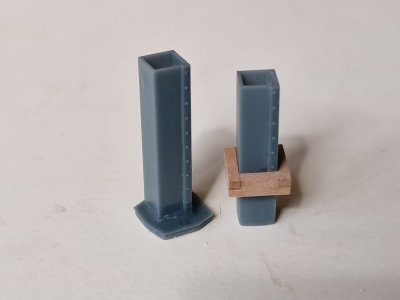
Stove and Flue.


Alert 2929.jpg

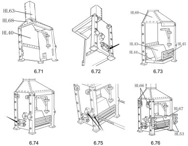
The kit includes metal parts for assembling the entire stove, and the quality is actually quite good.

Alert 2930.JPG

However, I’ve put that task on hold for now, since I don’t plan to install the stove inside the first hull; instead, I want to place it as a separate element of the overall display next to the ship (alongside the cannons, anchors, boat, and perhaps a few other items).

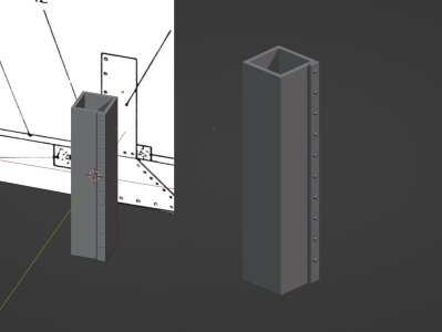
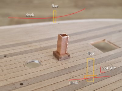
As for the second hull, the stove isn't fully visible anyway, so I initially modeled only the chimney—though "modeled" might be a bit of an overstatement! :)))))

Alert 2931.jpg

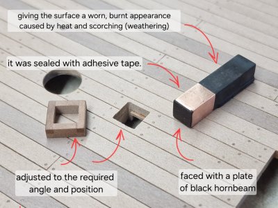
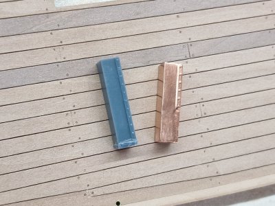
Then I 3D-printed it, fitted it to the frame, and coated it with copper.

Alert 2932.jpg

Alert 2933.jpg

Alert 2934.jpg

Alert 2934с.jpg

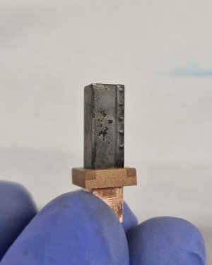
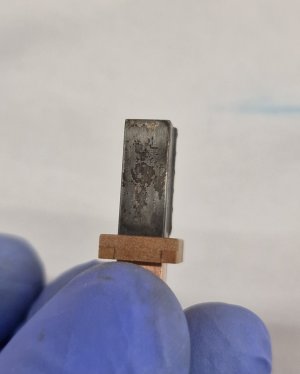
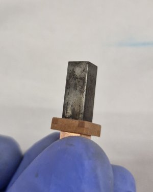
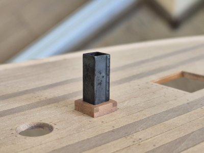
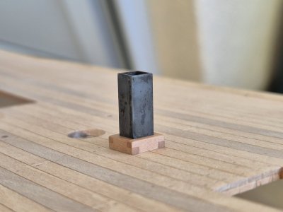
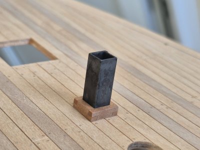
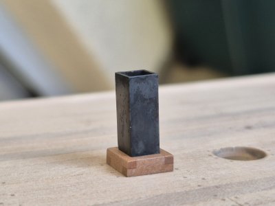
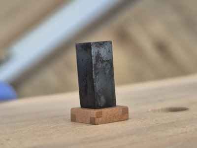
I started by inking it using my usual method, but the smokestack—with its very smooth, straight walls—looked boring and lacked a worn appearance. So, I applied some weathering. Since the metal heated up and accumulated soot—which would have been scrubbed off—combined with the effects of saltwater and temperature, the part clearly needed to look heavily weathered.

Here is the technique I used: After two standard applications, the part had already turned a dark graphite color. Next, I diluted some pure BB [Burnishing Fluid] with water—mixing it 1:1 (or with slightly more BB)—and applied it with a brush. The top layer began to break down and flake off in places, so I dabbed the tip of the brush against the surface to create localized areas of deterioration. Then, I gently brushed away the loose flakes. I repeated this process until I was completely satisfied with the result. I don't recommend doing this with undiluted BB, as it can leave purple streaks and severely damage the surface; that’s why it needs to be diluted with water. However, this likely only works on a polished surface like the one I had; I haven't tried it on a rough surface. Experimentation is key here...

Alert 2935.jpg

Alert 2936.jpg

Alert 2937.jpg

Alert 2938.jpg

Against the backdrop of the clean deck, this might seem excessive right now, but don't forget that my goal is a museum-quality look—and that involves bitumen, the play of shadows, and dark tones. So, in the end, this detail will blend in perfectly.

Alert 2939.jpg

Alert 2940.jpg

Alert 2941.jpg

Alert 2942.jpg

Alert 2943.jpg

I haven't glued anything together yet... each part is fabricated, test-fitted, photographed, and set aside until the time comes to secure it in place; in the meantime... the rigging winch is next on the list.
 
Kapitel 26. An Deck (Teil 4)

5/
Ofen und Rauchrohr.


View attachment 634360

Das Set enthält Metallteile zum Zusammenbau des gesamten Ofens, und die Qualität ist wirklich recht gut.

View attachment 634361

Allerdings habe ich diese Aufgabe vorerst auf Eis gelegt, da ich nicht vorhabe, den Ofen im Inneren des ersten Rumpfes einzubauen; stattdessen möchte ich ihn als separates Element der Gesamtdarstellung neben dem Schiff platzieren (zusammen mit den Kanonen, Ankern, dem Boot und vielleicht ein paar anderen Gegenständen).

Was den zweiten Rumpf angeht, ist der Ofen ohnehin nicht vollständig sichtbar, daher habe ich zunächst nur den Schornstein modelliert – wobei „modelliert“ vielleicht etwas übertrieben ist! :)))))

View attachment 634362

Dann habe ich es im 3D-Druckverfahren hergestellt, in den Rahmen eingepasst und mit Kupfer beschichtet.

View attachment 634363

View attachment 634364

View attachment 634365

View attachment 634366

Ich begann mit dem Tuschen nach meiner üblichen Methode, aber der Schornstein – mit seinen sehr glatten, geraden Wänden – wirkte langweilig und nicht abgenutzt. Deshalb fügte ich einige Alterungseffekte hinzu. Da sich das Metall erhitzt und Ruß angesammelt hatte – der normalerweise abgerieben worden wäre – und in Kombination mit den Auswirkungen von Salzwasser und Temperatur, musste das Teil eindeutig stark verwittert aussehen.

Hier ist die von mir verwendete Technik: Nach zwei Standardanwendungen hatte das Teil bereits eine dunkle Graphitfarbe angenommen. Anschließend verdünnte ich etwas reines Polierfluid (BB) mit Wasser – im Verhältnis 1:1 (oder mit etwas mehr BB) – und trug es mit einem Pinsel auf. Die oberste Schicht begann sich stellenweise abzulösen und abzublättern. Daher tupfte ich mit der Pinselspitze über die Oberfläche, um gezielt Abplatzungen zu erzeugen. Anschließend entfernte ich vorsichtig die losen Flocken. Diesen Vorgang wiederholte ich, bis ich mit dem Ergebnis vollkommen zufrieden war. Ich rate davon ab, dies mit unverdünntem BB zu tun, da es violette Streifen hinterlassen und die Oberfläche stark beschädigen kann; deshalb muss es mit Wasser verdünnt werden. Allerdings funktioniert diese Methode wahrscheinlich nur auf einer polierten Oberfläche wie meiner; auf einer rauen Oberfläche habe ich sie noch nicht ausprobiert. Hier ist Experimentieren gefragt…

View attachment 634371

View attachment 634372

View attachment 634373

View attachment 634374

Vor dem Hintergrund der makellosen Terrasse mag das im Moment übertrieben wirken, aber vergessen Sie nicht, dass mein Ziel ein museales Erscheinungsbild ist – und dazu gehören Bitumen, das Spiel der Schatten und dunkle Farbtöne. Letztendlich wird sich dieses Detail also perfekt einfügen.

View attachment 634381

View attachment 634382

View attachment 634383

View attachment 634384

View attachment 634385

Ich habe noch nichts zusammengeklebt... jedes Teil wird gefertigt, probeweise montiert, fotografiert und beiseitegelegt, bis es an der Zeit ist, es zu befestigen; in der Zwischenzeit... steht die Takelagewinde als nächstes auf der Liste.

Die Oberfläche wirkt wieder einmal unglaublich realistisch. Die Farbgebung ist sehr detailliert. Genau so stellt man sich einen ausgebrannten Kamin vor. Wirklich hervorragend gemacht.Jedes gefertigtes Bauteil wirkt wie ein eigenständiges Modell. Ich bin begeistert.
 
Last edited:
Chapter 26. On the Decks (Part 4)

6/
Windlass.


Alert 2944.JPG

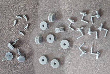
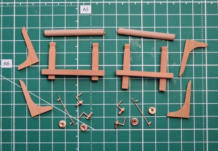
I had previously crafted the wooden parts for it, and I also showed how I made the metal elements.

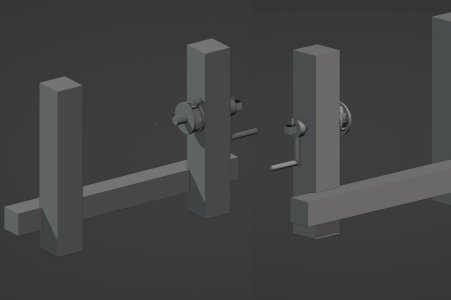
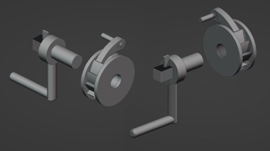
As a reminder, all the parts were modeled in the 3D program Blender.

Alert 2945.jpg

Alert 2946.jpg

Alert 2947.jpg

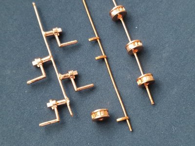
Then they were 3D-printed and copper-plated using an electroplating process.

Alert 2948.jpg

Alert 2949.jpg

After copper plating, they come out very smooth and shiny, so they require some processing and preparation before blackening. I also made the cylindrical parts out of dark pear wood so they would stand out from the main body (the top two parts in the photo below).

Alert 2950.jpg

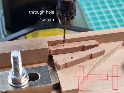
Then I drilled a few holes in the necessary places and...


Alert 2951.jpg

Alert 2952.jpg

Alert 2953.jpg

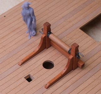
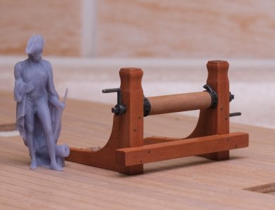
... and assembled the mechanism, shortening the cylindrical component so that it—together with two metal ratchets—formed the exact length corresponding to the distance between the carlings on the deck.

Alert 2954.jpg

There is no point in making the mechanism functional, so I’ll simply glue everything together; I’ll shorten the axles (iron nails) and attach handles to the sides.

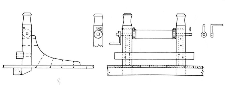
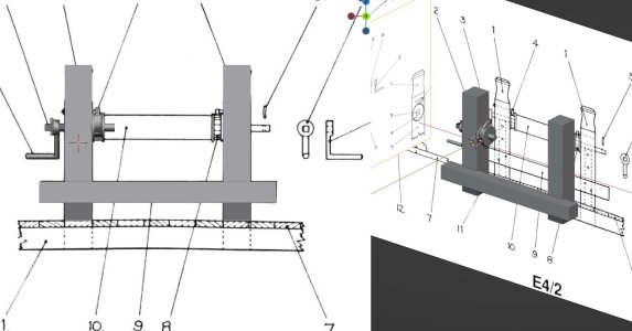
The question of the locking mechanism remains. The anatomy diagrams contradict themselves yet again. The main contradiction concerns the direction of the cylinder's rotation: does it turn from the bow, over the top, toward the stern, or from the stern, over the top, toward the bow? This determines the placement of the locking pin—whether it should point aft or forward. The anatomy shown is simply absurd; one image shows one configuration, while the second shows another. And to top it off, one view shows *both*—which defies common sense! I’ll investigate this further, but I think the logic is straightforward: I should look to the forward anchor mechanism for an analogy, as that setup is perfectly clear. The movement went from the bow, over the top, toward the stern. I am virtually certain the aft mechanism operated the same way.

Alert 2956.jpg
 
Kapitel 26. An Deck (Teil 4)

6/
Ankerwinde.

View attachment 635102

Ich hatte zuvor die Holzteile dafür angefertigt und auch gezeigt, wie ich die Metallelemente hergestellt habe.
Zur Erinnerung: Alle Teile wurden im 3D-Programm Blender modelliert.

View attachment 635103

View attachment 635104

View attachment 635105

Anschließend wurden sie im 3D-Druckverfahren hergestellt und mittels Galvanisierung verkupfert.

View attachment 635106

View attachment 635107

Nach der Kupferplattierung sind sie sehr glatt und glänzend, daher müssen sie vor dem Schwärzen noch etwas bearbeitet und vorbereitet werden. Die zylindrischen Teile habe ich aus dunklem Birnenholz gefertigt, damit sie sich vom Hauptteil abheben (die beiden oberen Teile im unteren Bild).

View attachment 635110

Dann bohrte ich an den nötigen Stellen ein paar Löcher und...


View attachment 635114

View attachment 635116

View attachment 635118

... und montierte den Mechanismus, indem er das zylindrische Bauteil so verkürzte, dass es – zusammen mit zwei Metallratschen – genau die Länge aufwies, die dem Abstand zwischen den Karren auf dem Deck entsprach.

View attachment 635124

Es macht keinen Sinn, den Mechanismus funktionsfähig zu machen, also werde ich einfach alles zusammenkleben; Ich werde die Achsen (Eisennägel) kürzen und Griffe an den Seiten anbringen.

Die Frage nach dem Verriegelungsmechanismus bleibt offen. Die Darstellungen widersprechen sich erneut. Der Hauptwiderspruch betrifft die Drehrichtung des Zylinders: Dreht er sich vom Bug über die Spitze zum Heck oder vom Heck über die Spitze zum Bug? Dies bestimmt die Position des Verriegelungsbolzens – ob er nach achtern oder nach vorn zeigen soll. Die gezeigte Darstellung ist schlichtweg absurd; Ein Bild zeigt die eine Konfiguration, das zweite die andere. Und als ob das nicht genug wäre, zeigt eine Ansicht *beide* – was aller Logik widerspricht! Ich werde der Sache weiter nachgehen, aber ich denke, die Logik ist einfach: Ich sollte mir den vorderen Ankermechanismus als Analogie ansehen, da dessen Aufbau vollkommen klar ist. Die Bewegung verlief vom Bug über die Spitze zum Heck. Ich bin mir nahezu sicher, dass der hintere Mechanismus funktioniert.
View attachment 635125
Und wieder zeigt sich, dass gute Recherche unerläßlich ist.Sich nicht uneingeschränkt auf eine Bauanleitung verlassen oder Literatur als „gesetzt“ ansehen. Immer alles in Frage stellen. Der Baubericht ist wie eine „Arbeits-Bibel“. Klasse, was für ein schönes Niveau.
 
Chapter 26. On the Decks (Part 4)

6/
Windlass.


View attachment 635102

I had previously crafted the wooden parts for it, and I also showed how I made the metal elements.

As a reminder, all the parts were modeled in the 3D program Blender.

View attachment 635103

View attachment 635104

View attachment 635105

Then they were 3D-printed and copper-plated using an electroplating process.

View attachment 635106

View attachment 635107

After copper plating, they come out very smooth and shiny, so they require some processing and preparation before blackening. I also made the cylindrical parts out of dark pear wood so they would stand out from the main body (the top two parts in the photo below).

View attachment 635110

Then I drilled a few holes in the necessary places and...


View attachment 635114

View attachment 635116

View attachment 635118

... and assembled the mechanism, shortening the cylindrical component so that it—together with two metal ratchets—formed the exact length corresponding to the distance between the carlings on the deck.

View attachment 635124

There is no point in making the mechanism functional, so I’ll simply glue everything together; I’ll shorten the axles (iron nails) and attach handles to the sides.

The question of the locking mechanism remains. The anatomy diagrams contradict themselves yet again. The main contradiction concerns the direction of the cylinder's rotation: does it turn from the bow, over the top, toward the stern, or from the stern, over the top, toward the bow? This determines the placement of the locking pin—whether it should point aft or forward. The anatomy shown is simply absurd; one image shows one configuration, while the second shows another. And to top it off, one view shows *both*—which defies common sense! I’ll investigate this further, but I think the logic is straightforward: I should look to the forward anchor mechanism for an analogy, as that setup is perfectly clear. The movement went from the bow, over the top, toward the stern. I am virtually certain the aft mechanism operated the same way.

View attachment 635125
I would guess that they would have one going each way. One would ratchet one way and the other one would be used to ratchet the other way. Obviously, one would be lifted out of position to get the ratchet to go the way you want. Again, this is purely a guess on my part since it doesn't make sense to have both ratchet the same way. Why would you need that.
 
I agree with Jeff’s opinion. You will have to use the windlass in both directions. Then one of the two locks has to take out of the gear. By turning the other way, you change the position of the locks.
Regards, Peter
 
Die Oberfläche wirkt wieder einmal unglaublich realistisch. Die Farbgebung ist sehr detailliert. Genau so stellt man sich einen ausgebrannten Kamin vor. Wirklich hervorragend gemacht.Jedes gefertigtes Bauteil wirkt wie ein eigenständiges Modell. Ich bin begeistert.
Veeeerrry nice! :-)
The weathering is absolutely perfect ! I love it !!!
Und wieder zeigt sich, dass gute Recherche unerläßlich ist.Sich nicht uneingeschränkt auf eine Bauanleitung verlassen oder Literatur als „gesetzt“ ansehen. Immer alles in Frage stellen. Der Baubericht ist wie eine „Arbeits-Bibel“. Klasse, was für ein schönes Niveau.
Friends! Thank you so much for your comments and reactions. Your words continue to motivate me—thank you.

I would guess that they would have one going each way. One would ratchet one way and the other one would be used to ratchet the other way. Obviously, one would be lifted out of position to get the ratchet to go the way you want. Again, this is purely a guess on my part since it doesn't make sense to have both ratchet the same way. Why would you need that.
I agree with Jeff’s opinion. You will have to use the windlass in both directions. Then one of the two locks has to take out of the gear. By turning the other way, you change the position of the locks.
Regards, Peter
I have to disagree; while the idea seems logical at first glance, that is not how it actually worked. The way it was depicted was simply a mistake. The ratchets operated in tandem and were mirror images of each other. The locking mechanisms also worked in pairs, reinforcing one another from both sides. The operating principle was as follows: the rope was not permanently fixed to the cylinder but wrapped around it three or four times; while the end was being pulled, the crew would rotate the cylinder to wind the rope onto it. As winding progressed, the crew pulled the rope end away from the mechanism, and the system functioned thanks to friction. To halt the process, the mechanism was locked using stopper pins. Then, while the crew held the end, the friction generated by the four wraps around the cylinder reduced the effective load hundreds of times over, allowing even a single sailor to hold a colossal weight. To remove the rope from the mechanism, a second rope—firmly secured to the deck—was tied to the main rope above the cylinder; the main rope was then untied from the cylinder and secured to the bitts. To lower the load, the mechanism was locked so the cylinder would not rotate; the crew simply eased the tension, allowing the line to pay out gradually while the friction from the wraps around the cylinder controlled the descent. This friction made it possible to lower immense weights safely.

The only question is which way the cylinder was rotating, but judging by the tendency of the front anchor mechanism, the direction is the same.
 
Last edited:
Friends! Thank you so much for your comments and reactions. Your words continue to motivate me—thank you.


I have to disagree; while the idea seems logical at first glance, that is not how it actually worked. The way it was depicted was simply a mistake. The ratchets operated in tandem and were mirror images of each other. The locking mechanisms also worked in pairs, reinforcing one another from both sides. The operating principle was as follows: the rope was not permanently fixed to the cylinder but wrapped around it three or four times; while the end was being pulled, the crew would rotate the cylinder to wind the rope onto it. As winding progressed, the crew pulled the rope end away from the mechanism, and the system functioned thanks to friction. To halt the process, the mechanism was locked using stopper pins. Then, while the crew held the end, the friction generated by the four wraps around the cylinder reduced the effective load hundreds of times over, allowing even a single sailor to hold a colossal weight. To remove the rope from the mechanism, a second rope—firmly secured to the deck—was tied to the main rope above the cylinder; the main rope was then untied from the cylinder and secured to the bitts. To lower the load, the mechanism was locked so the cylinder would not rotate; the crew simply eased the tension, allowing the line to pay out gradually while the friction from the wraps around the cylinder controlled the descent. This friction made it possible to lower immense weights safely.

The only question is which way the cylinder was rotating, but judging by the tendency of the front anchor mechanism, the direction is the same.
I see. Well, you would definitely know better than I would. :)
 
Chapter 26. On the Decks (Part 4)

7/
Windlass.
(continuation)

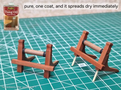
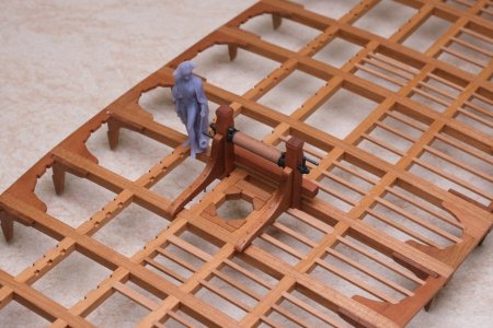
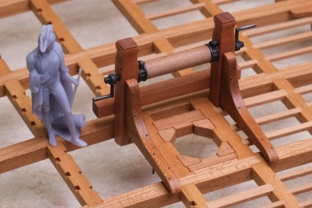
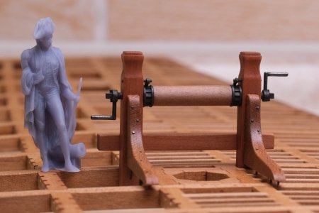
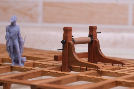
Continuing on... I installed the locking mechanism and anchor pins to reinforce the hold. Then I blackened the copper, glued everything together, and finished it with Tung oil.

Alert 2957.jpg

Alert 2958.jpg

Alert 2959.jpg

Alert 2960.jpg

Alert 2961.jpg

Alert 2962.jpg

Alert 2963.jpg

Alert 2964.jpg

Alert 2965.jpg

Alert 2966.jpg

Alert 2967.jpg

Alert 2968.jpg

Alert 2969.jpg


Alert 2971.jpg

Alert 2970.jpg

Alert 2972.jpg

Alert 2973.jpg

Once the oil dries, all that remains is to attach the handles and locking pins... and next time, I’ll show you how it all looks on the decks.
 
Kapitel 26. An Deck (Teil 4)

7/
Ankerwinde.
(Fortsetzung)

Weiter ging es… Ich habe den Verriegelungsmechanismus und die Ankerbolzen zur Verstärkung der Verbindung montiert. Anschließend schwärzte ich das Kupfer, verklebte alles und behandelte es abschließend mit Tungöl.

View attachment 636041

View attachment 636042

View attachment 636045

View attachment 636047

View attachment 636048

View attachment 636049

View attachment 636050

View attachment 636051

View attachment 636052

View attachment 636053

View attachment 636054

View attachment 636055

View attachment 636056


View attachment 636058

View attachment 636057

View attachment 636059

View attachment 636060

Sobald das Öl getrocknet ist, müssen nur noch die Griffe und Verriegelungsstifte angebracht werden... und beim nächsten Mal zeige ich euch, wie das Ganze auf dem Deck aussieht.
Wieder eine absolute Klasse Optik. Wunderbar erklärt und dargestellt. Einfach klasse wie Du jeden Schritt ,nachvollziehbar beschreibst. Dein Baubericht ist sehr wertvoll für Jeden. Profi und für Anfänger / Einsteiger. Ich glaube besser, geht es nicht. Danke dafür. Dein Baubericht und die gezeigten Ergebnisse ( mit all den Bauschritte dazu ) motiviert sehr.
 
Chapter 26. On the Decks (Part 4)

8/
Windlass.
(conclusion)

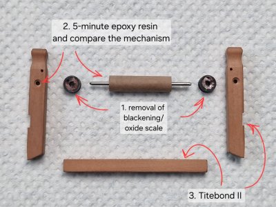
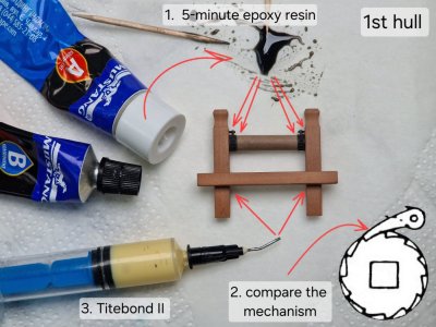
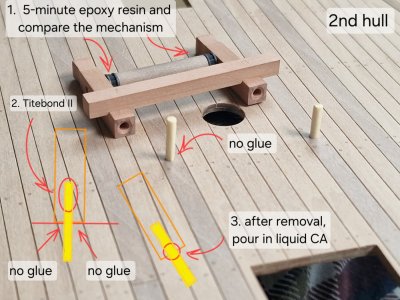
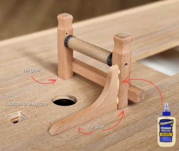
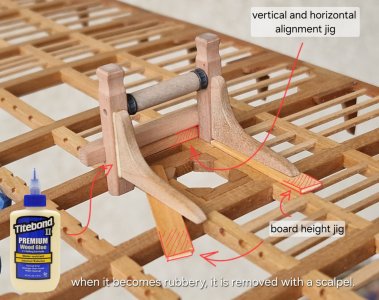
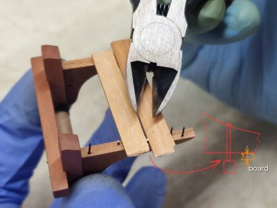
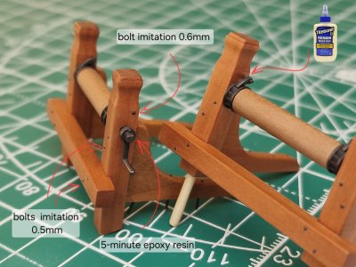
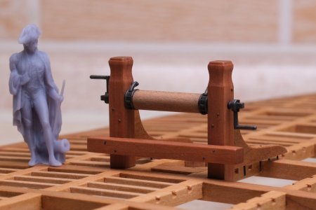
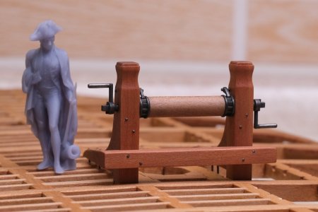
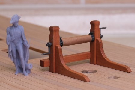
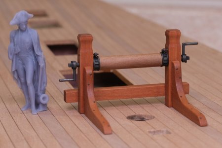
I glued the handles in place using five-minute epoxy, which is very convenient for setting the correct angle and position. I glued the retaining pins using Titebond II, injecting the adhesive into the hole with a syringe before inserting the pin and wiping away the excess. This method is convenient because it allows for clean application; since this component isn't load-bearing, this type of bond is sufficient, and it also makes future repairs easier. On the opposite side, I installed a 0.6 mm bolt.

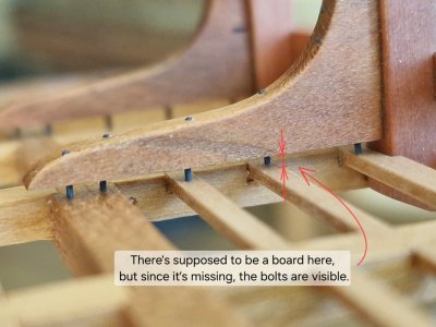
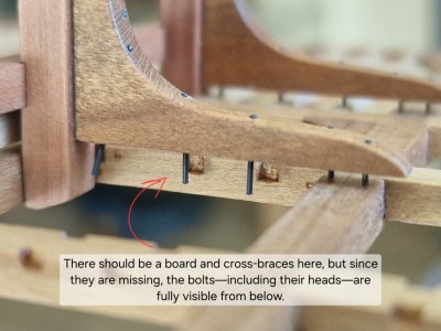
I also installed bolts (made from 0.5 mm brass wire). Since the ship model's hull lacks deck planking—yet the knee rests against the deck—I positioned the bolts so they remain visible; they are exposed not only due to the absence of planks but also, on one side, because there are no cross-members between the carlings.

Alert 2974.jpg

Alert 2975.jpg

Alert 2976.jpg

Alert 2977.jpg

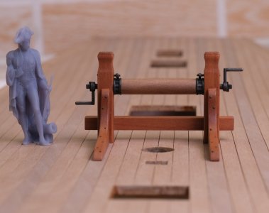
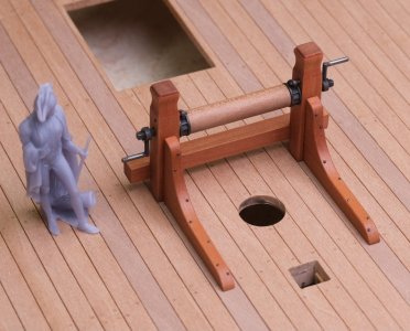
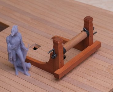
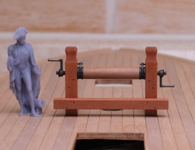
And here’s the result... I finally managed to set up good lighting, and the photos turned out pretty well.

Alert 2978.JPG

Alert 2979.JPG

Alert 2980.JPG

Alert 2981.JPG

Alert 2982.JPG

Alert 2983.JPG

Alert 2984.JPG

Alert 2985.JPG

Alert 2986.JPG

Alert 2987.JPG

Alert 2988.JPG

Alert 2989.JPG

Alert 2990.JPG

Alert 2991.JPG

In the top photo, you can clearly see the handles gleaming right where I simulated exposed metal—the result of constant friction from the hands turning.

That wraps things up for these components; next up is the anchor mechanism... and that’s where things get more interesting—and far more complex.
 
Last edited:
Back
Top